¶ Navigation
OAE Assembly Part 1: RA Gearbox
OAE Assembly Part 2: Base
OAE Assembly Part 3: DEC
OAE Assembly Part 4: AZ Base
OAE Assembly Part 5: ALT and Final Assembly
OAE Additional Assembly
¶ OpenAstroExplorer Assembly Part 4: Azimuth Base
In this step:
¶ Step 36
- Assembly
- Parts
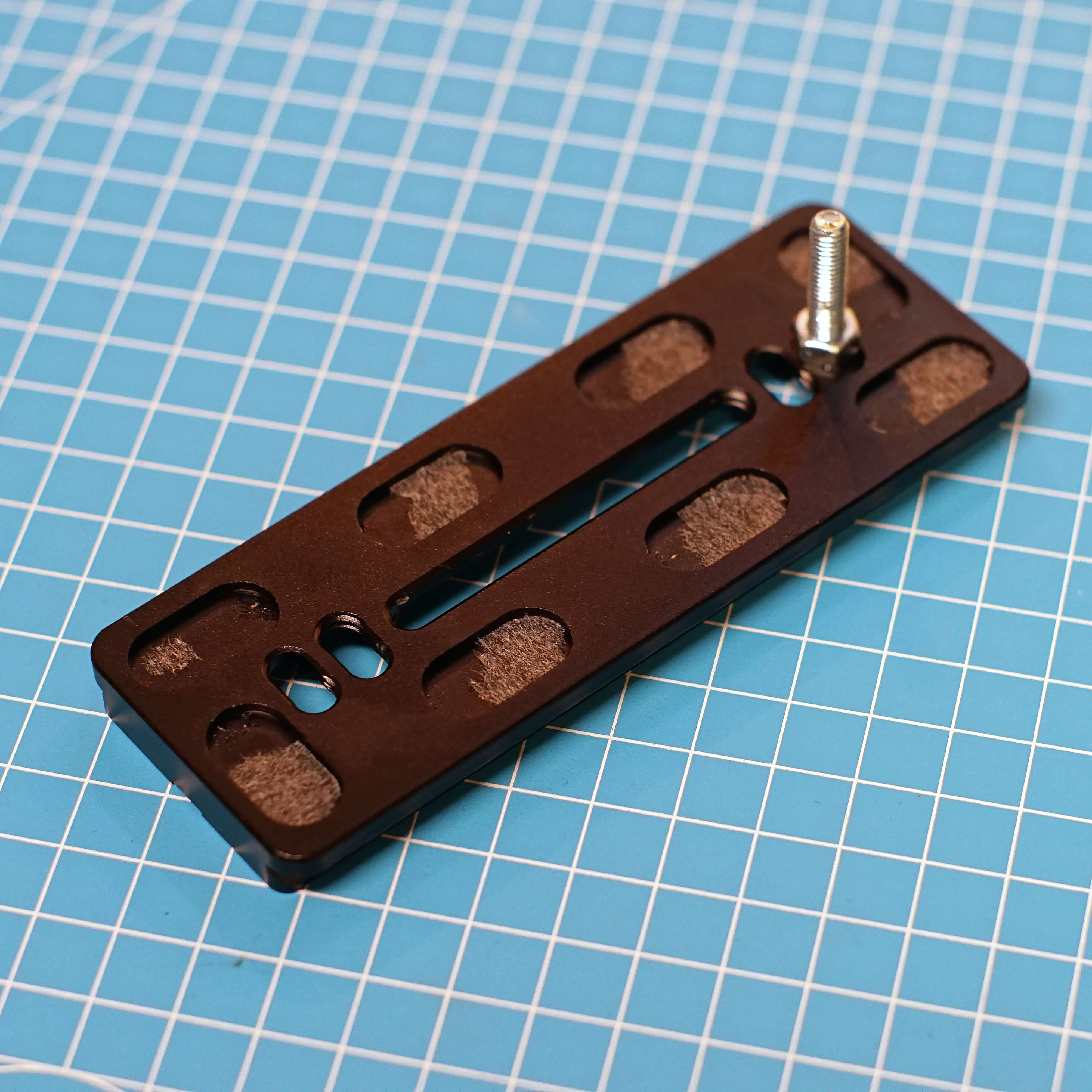
- Remove the rubber pieces, 3/8" screw and the little M3 screw on the bottom from the clamp.
- Attach the screw with a nut as shown. Try to get it as centered as possible. Hold the nut with a spanner or pliers, then tighten.
¶ Hardware
- 120 Arcaswiss Plate
- M5x25
- M5 Nut
¶ Step 37
- Assembly
- Parts
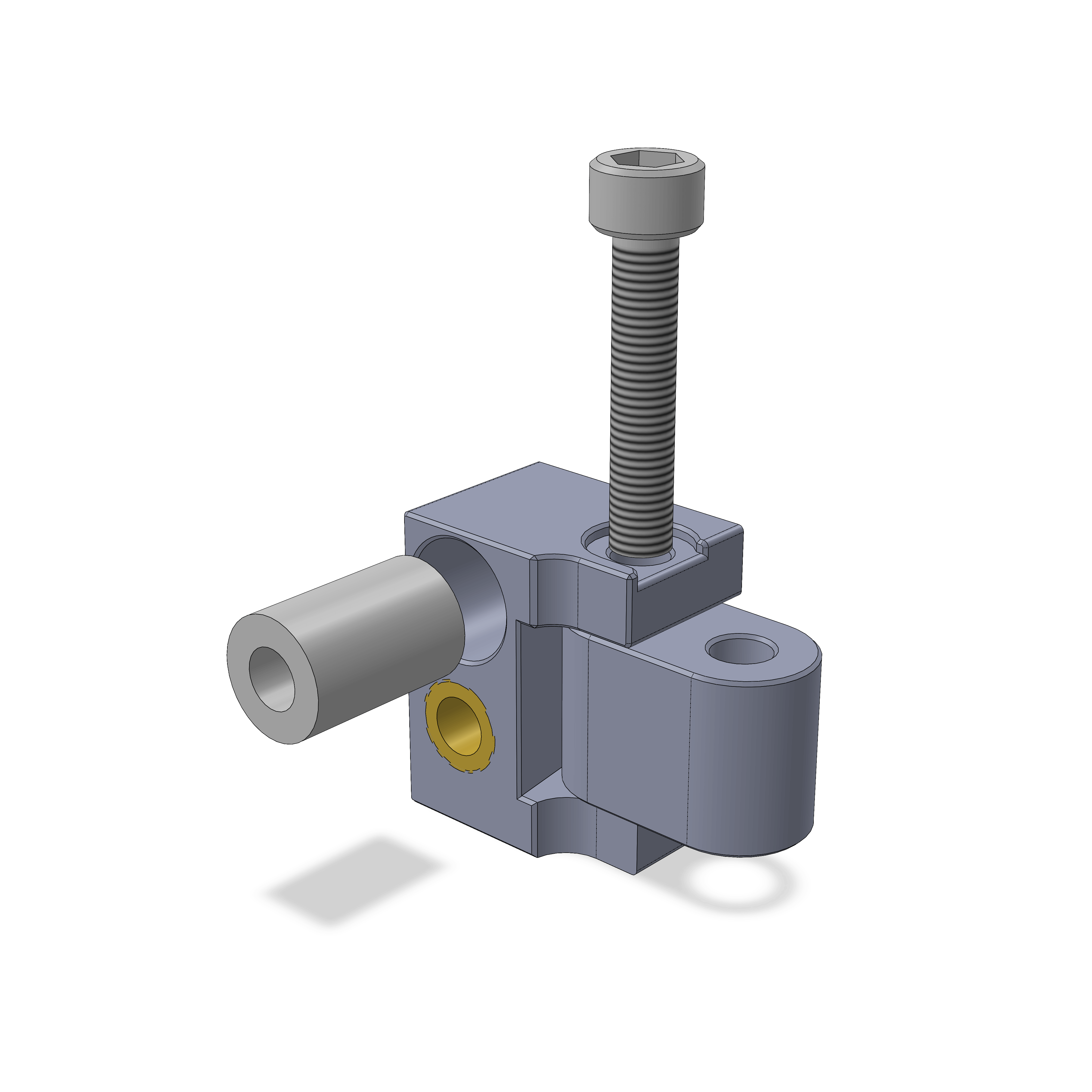
- Insert the LM5UU bearing as shown, you may have to (very carefully) hammer it in.
- Use a M5 screw to attach the connector. It should be able to move with medium force, if it's too hard try screwing the screw in and out a few times, or add grease.
¶ Step 38
- Assembly
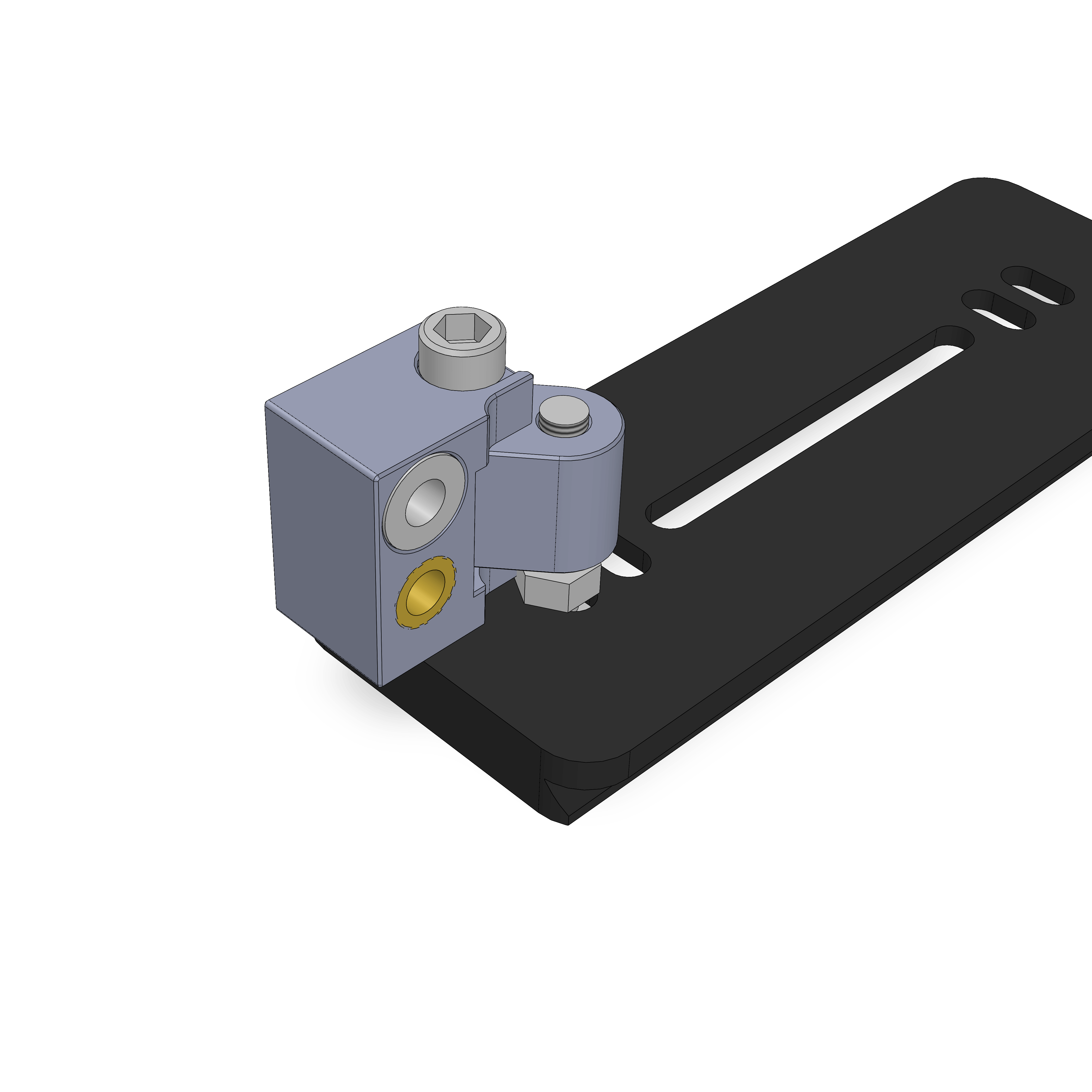
- Screw the assembly on as shown. It should also be able to rotate with medium force, take the same steps as above if not. There should be about 1mm of spacing to the arcaswiss plate.
¶ Step 39
- Assembly
- Parts
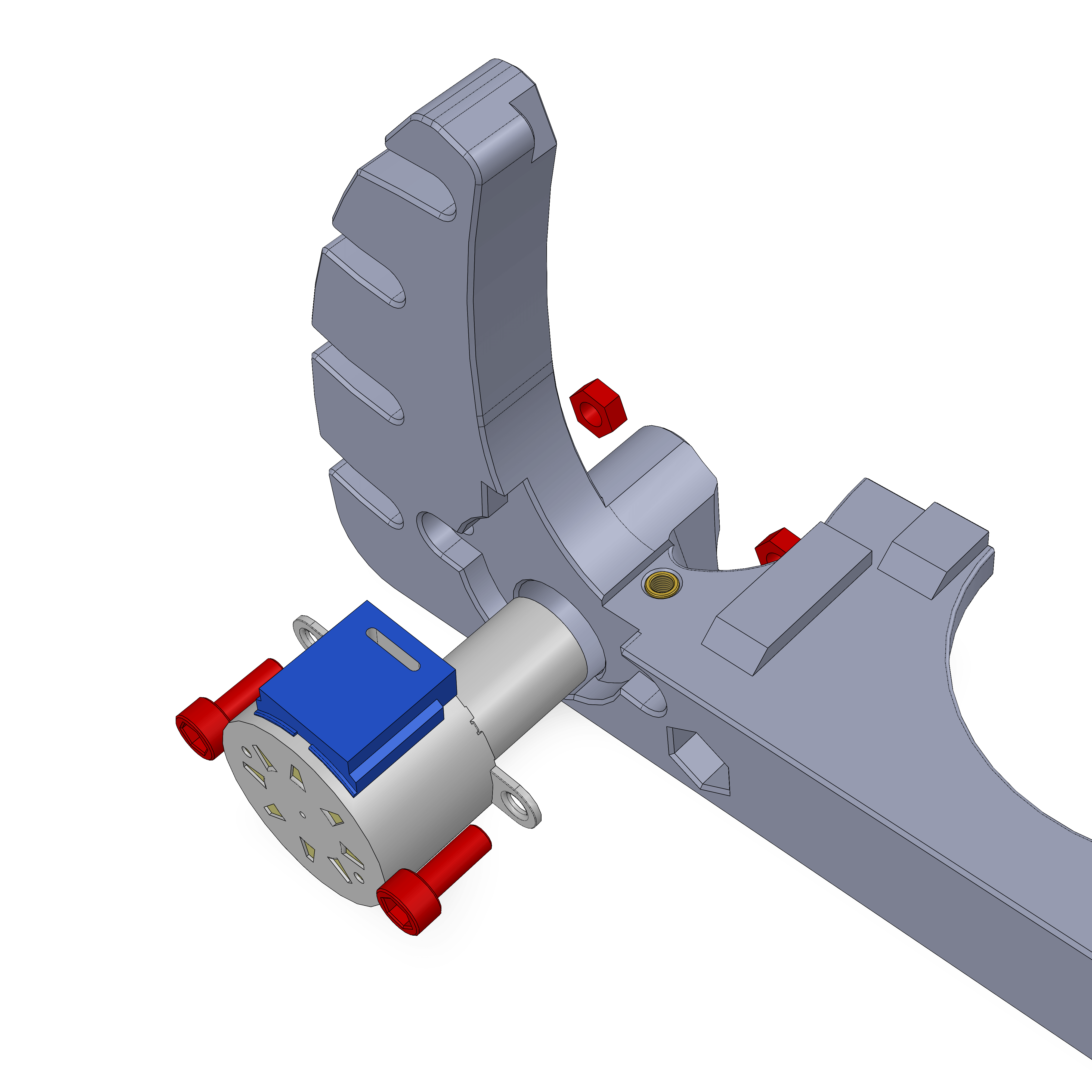
- Attach the 5-5 Shaft coupler to the stepper. Rotate it so that te grub screws point towards the bottom.
- Add the M4 Nuts, then push in the stepper.
- Attach with 2 M4x10 screws
¶ Step 40
- Assembly
- Parts
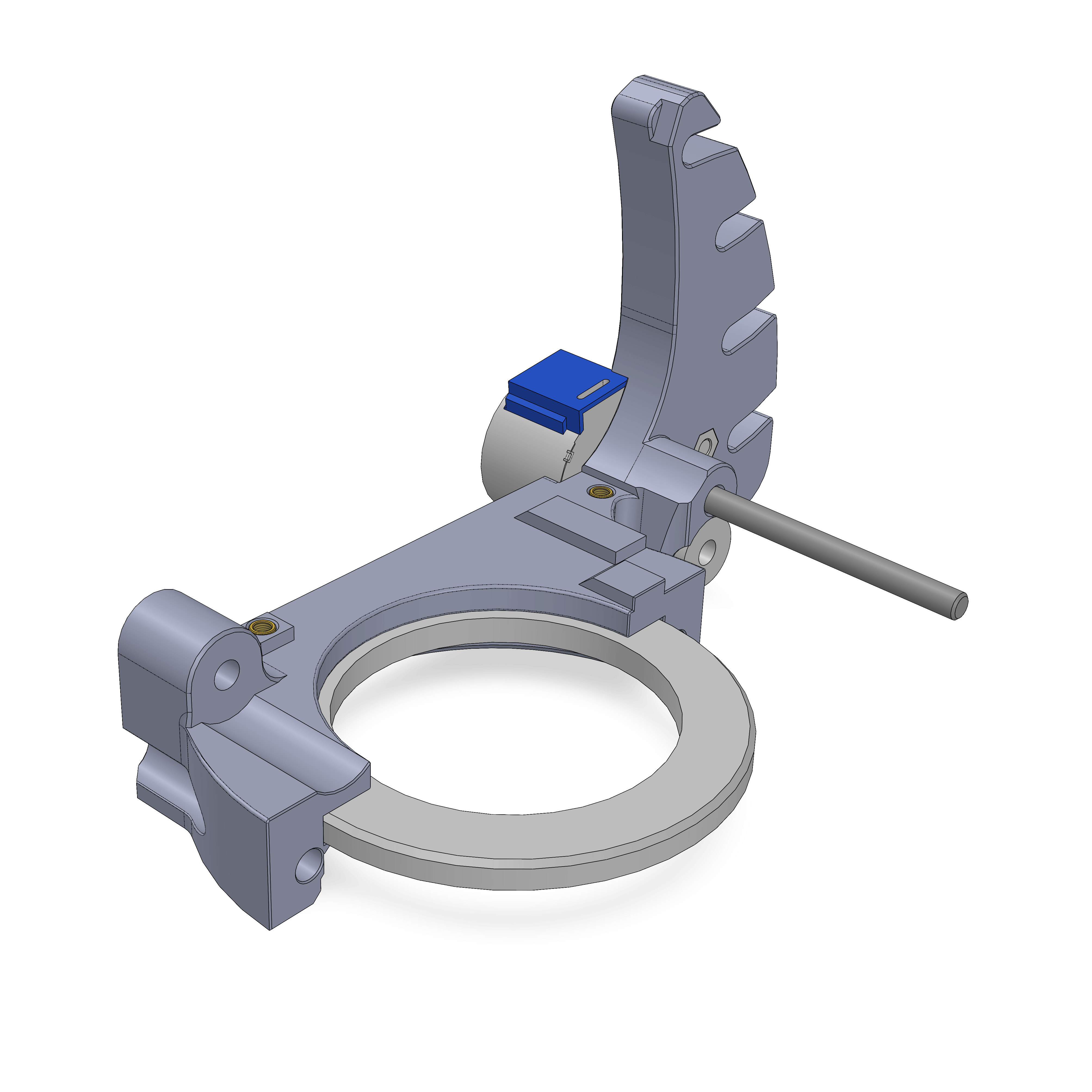
- There are two halfes of the 51111 bearing. The top one is the one where the F6006 bearing fits into perfectly, the bottom half has a larger cutout. Push the top half into the part.
- Push the 5x60mm shaft into the part.
¶ Hardware
- Top half of 51111 bearing
- 5x60mm shaft
¶ Step 41
- Assembly
- Parts
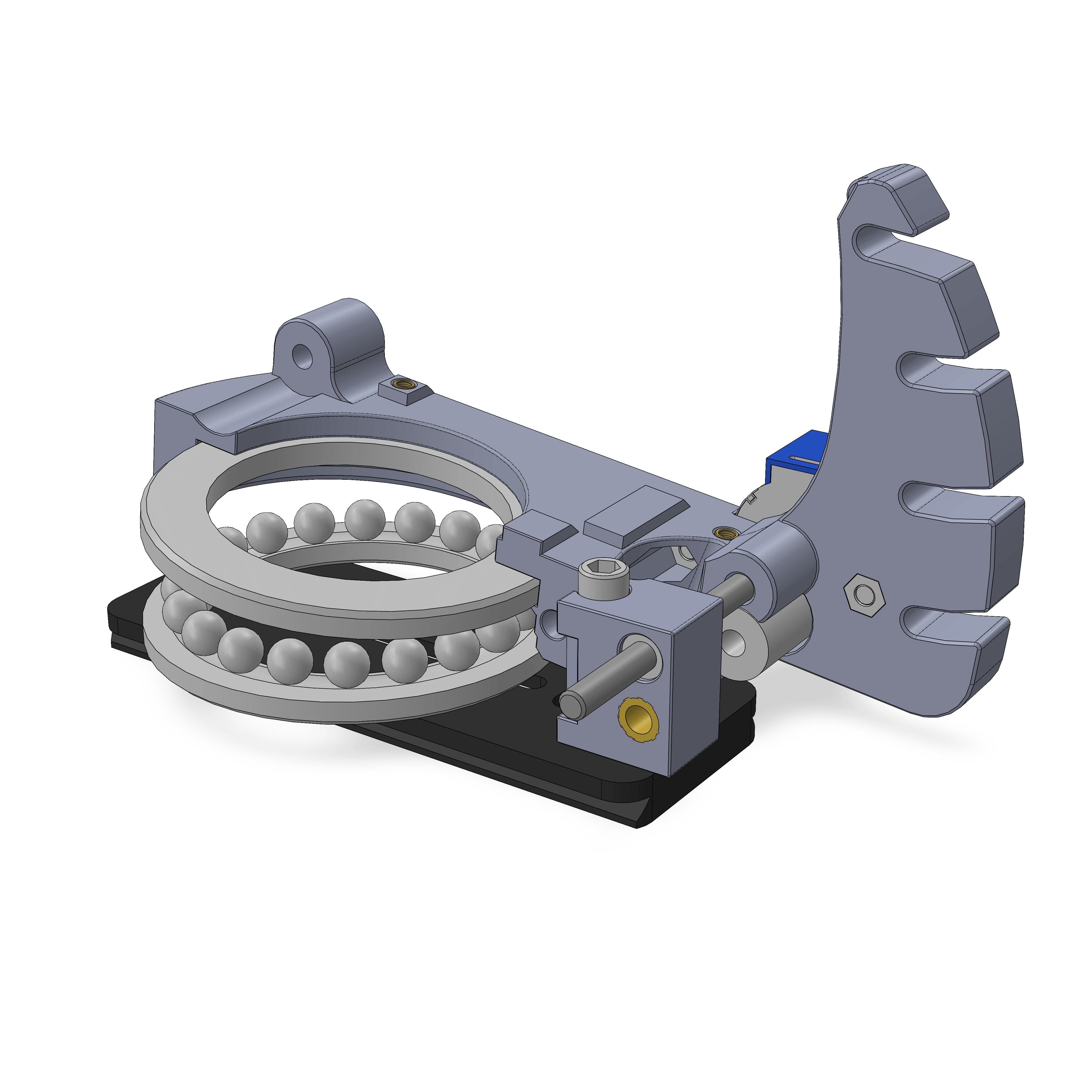
- Insert the shaft into the LM5UU bearing as shown.
- Also add the rest of the 51111 bearing underneath.
¶ Hardware
- Bottom half and ball ring of 51111 bearing
- Assembly from Step 38
¶ Step 42
- Assembly
- Parts
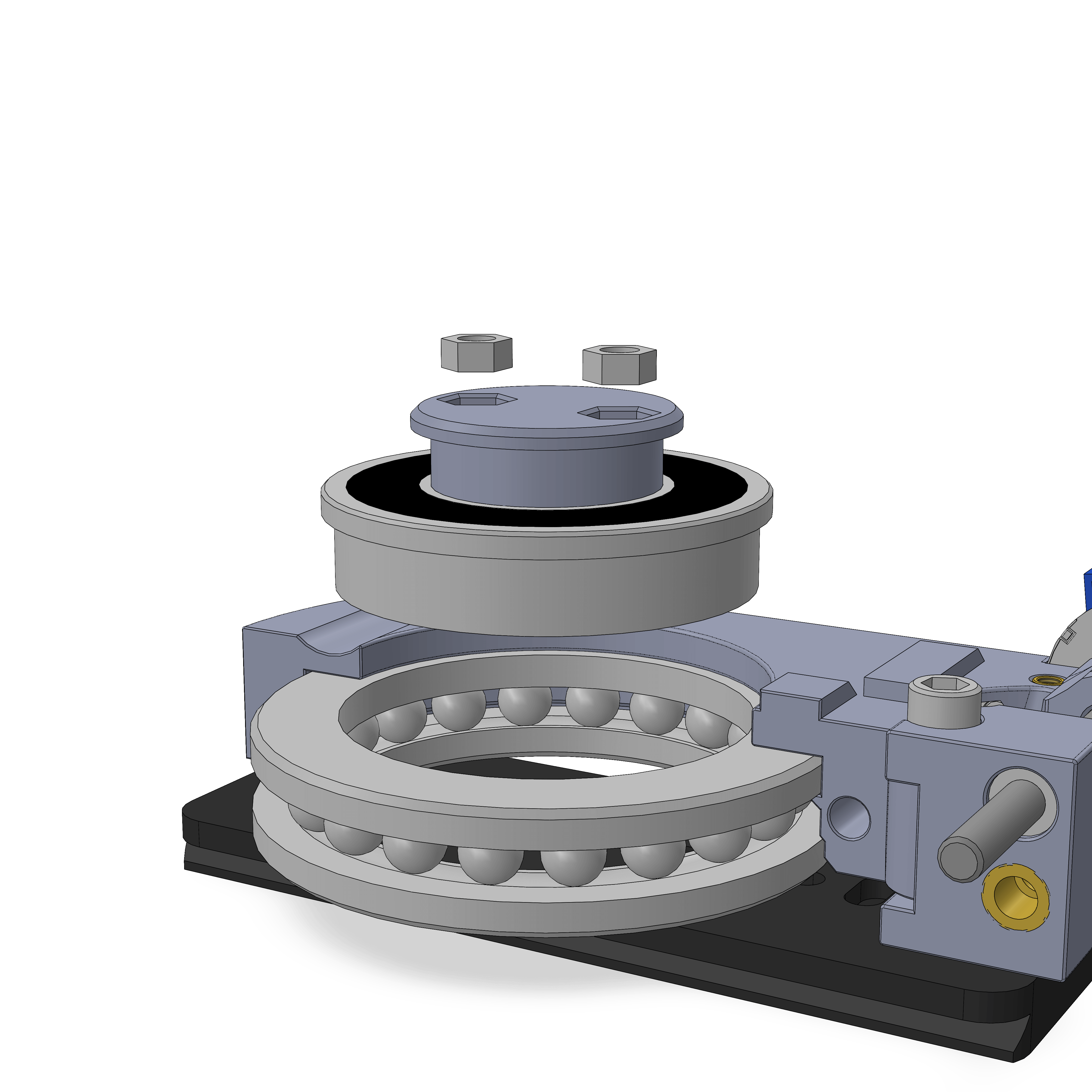
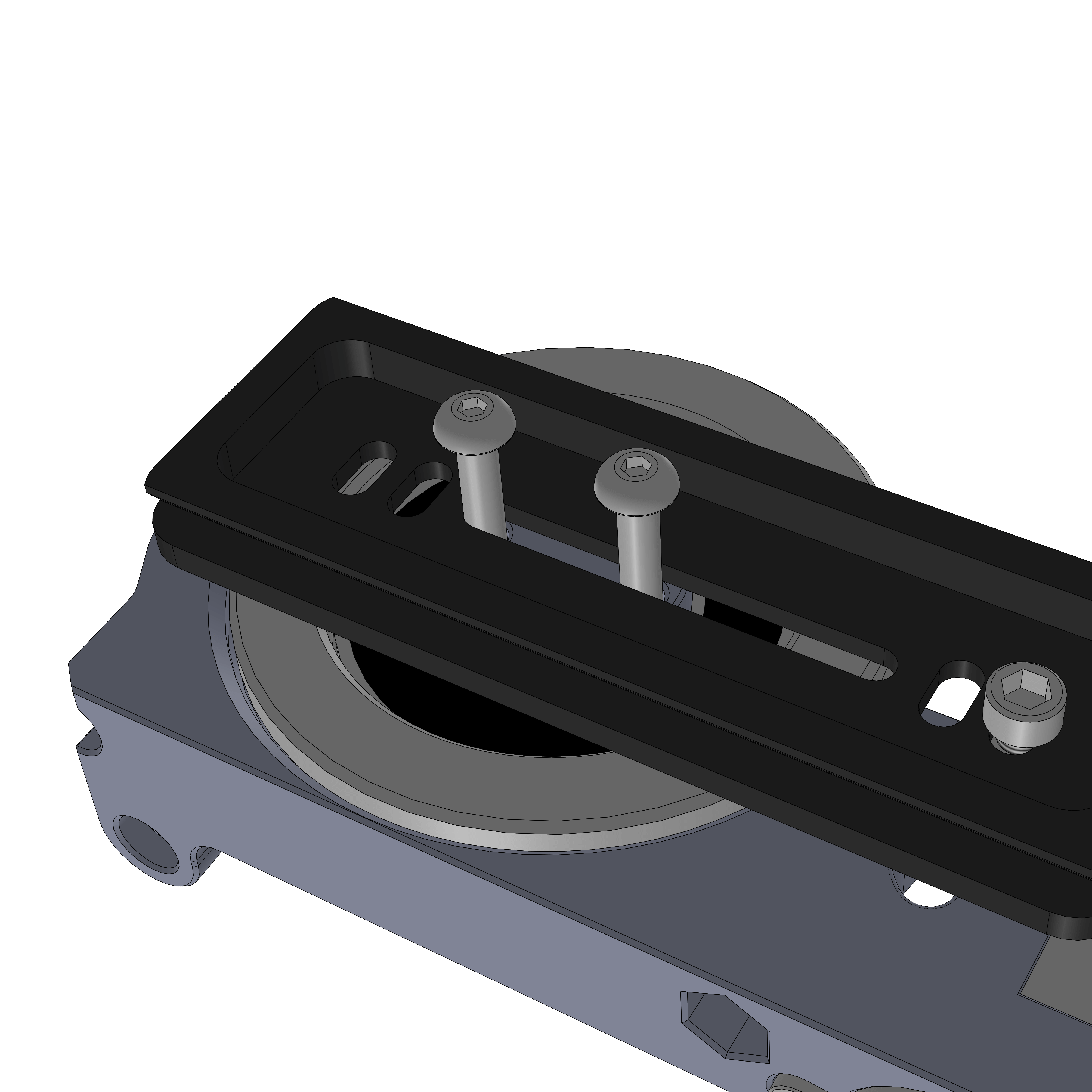
- Insert 2 M5x25 Flathead screws into the AZ coupler, push it into the F6006 bearing and insert it into the 51111 bearing.
- Note: Previous versions of the AZ_coupler used M5x20 scews inserted from the bottom and for a brief period you may have received normal M5x25 screws (non flathead) that would also be inserted from the bottom with the nuts on the top.
¶ Step 43
- Assembly
- Parts
- Use two M5 Nuts to attach.
- Tighten the M5x25 screws while holding the Nuts with pliers or a spanner.
- You can now observe how the AZ Mechanism will work. Now is a good time to put a few drops of oil on the shaft.
¶ Hardware
- 2x M5 Nuts
¶ Step 44
- Assembly
- Parts
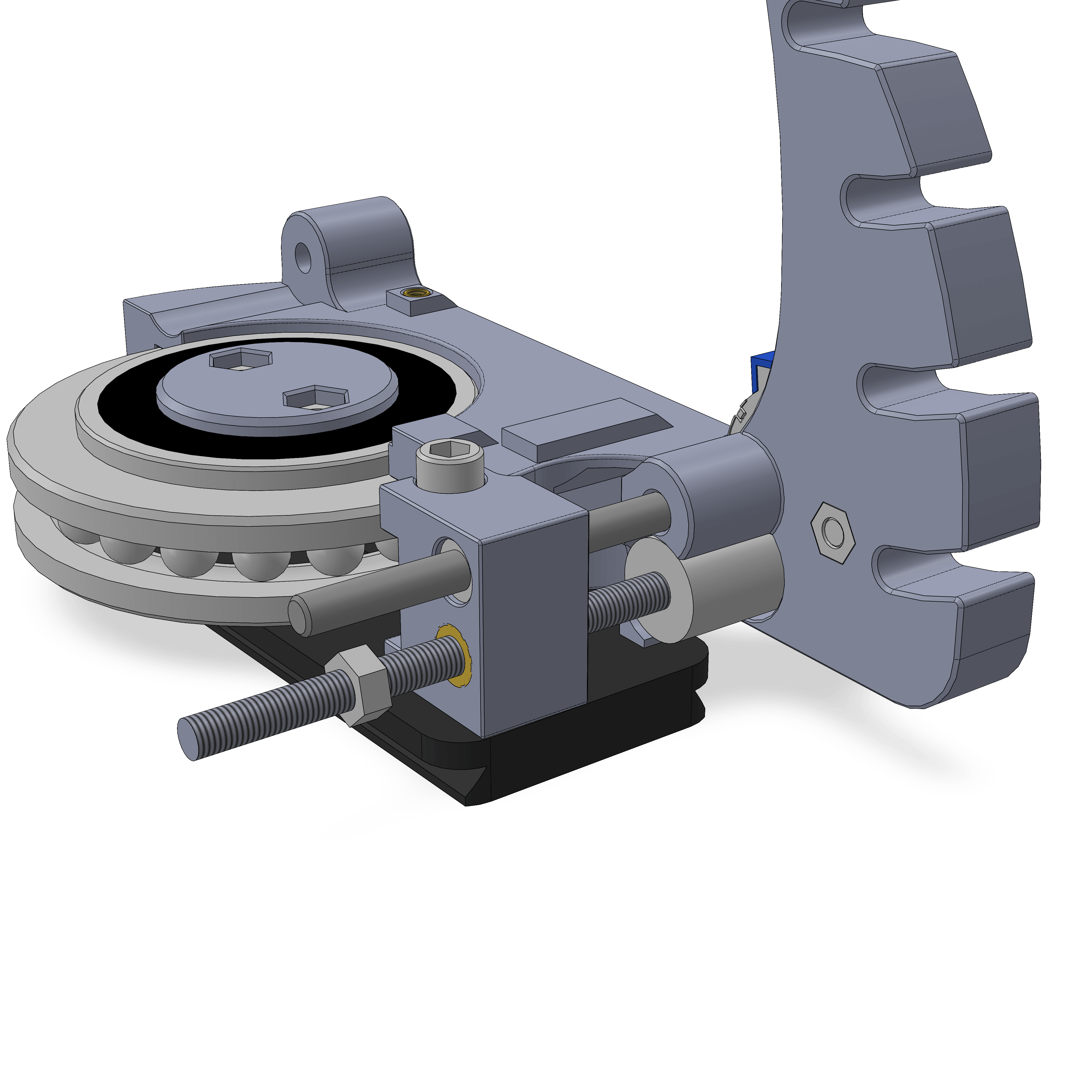
- Add the M5x70 threaded rod by screwing it through the two inserts. Now is a good time to add a bit of grease to the rod. Push it into the shaft coupler as far as it goes, then tighten the grub screws.
- Add a M5 Nut as shown, it doesn't get tightened against anything yet.
¶ Hardware
- M5x70 threaded rod
- M5 Nut
¶ Step 45
- Assembly
- Parts
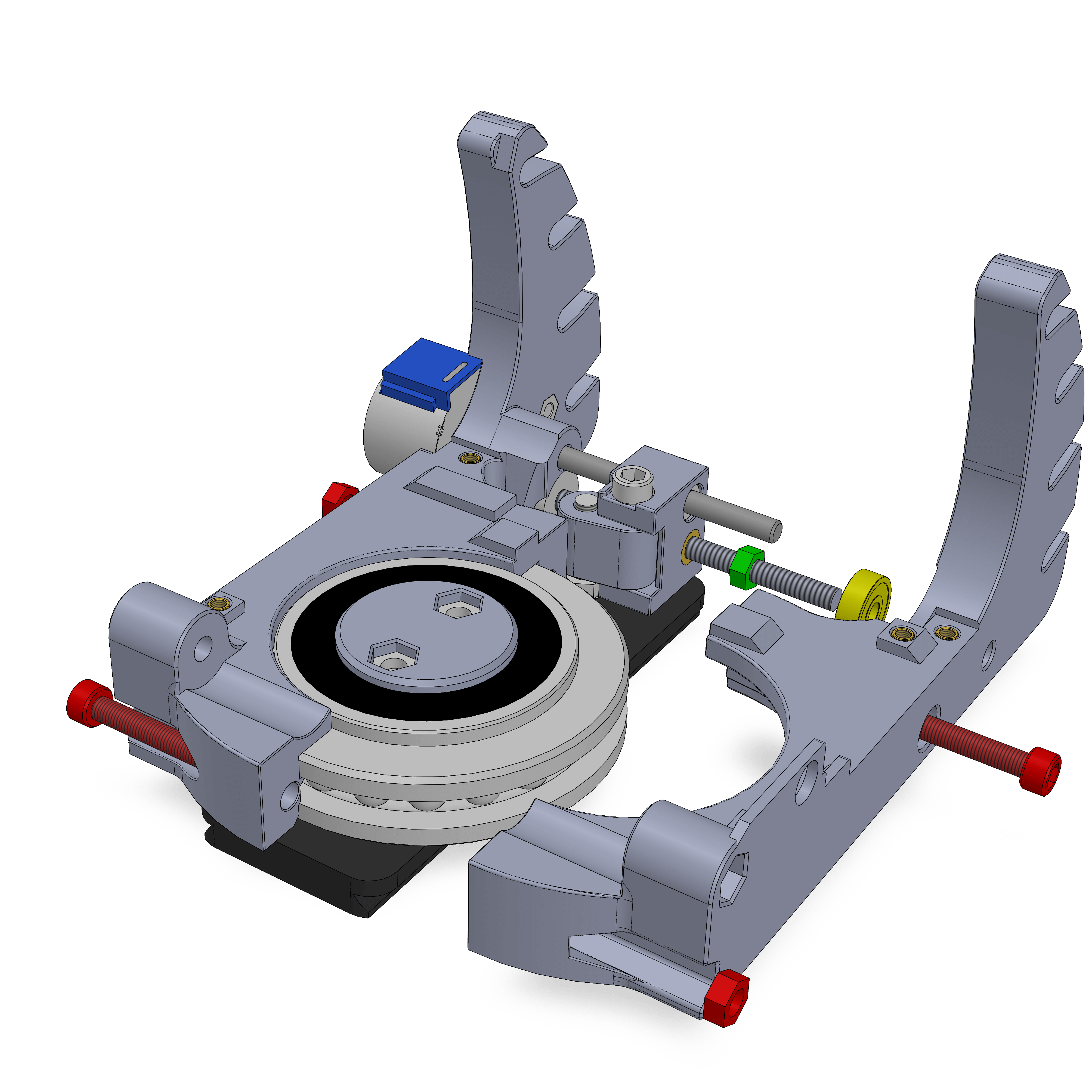
- Push a 625 bearing (yellow) into the other base half.
- Attach the half with two M5x30 and M5 Nuts.
- Lightly tighten the M5 Nut (green) against the bearing.
¶ Step 46
- Assembly
- Parts
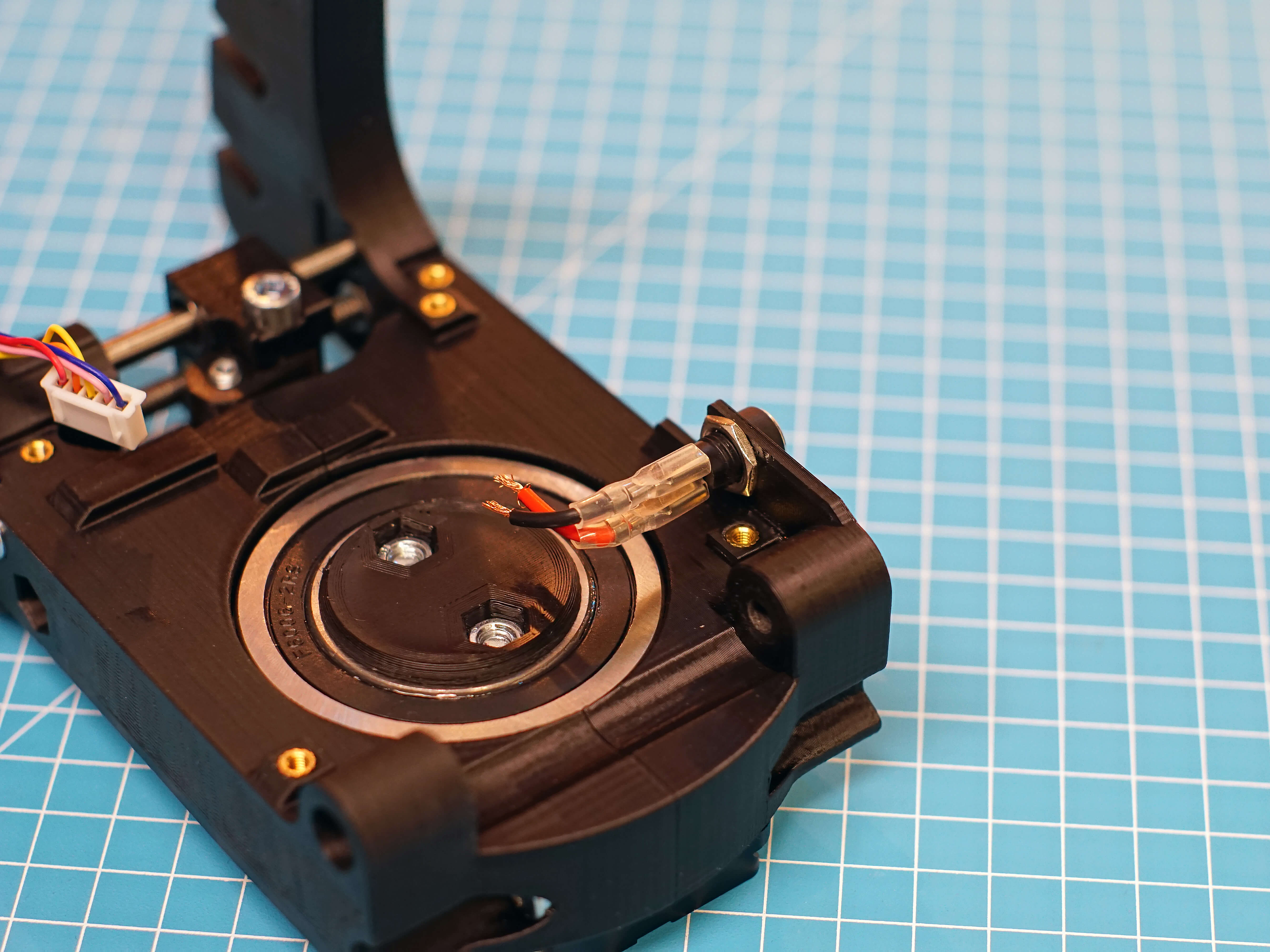
- Insert the DC barrel into the hole on the side of the base. Attach it with its nut.
- Attach the two connector cables. The short pin the barrel is positive/+/red, the longer pin is ground/-/black.
¶ Hardware
- DC barrel + Nut
- Spade connector cables
¶ Step 47
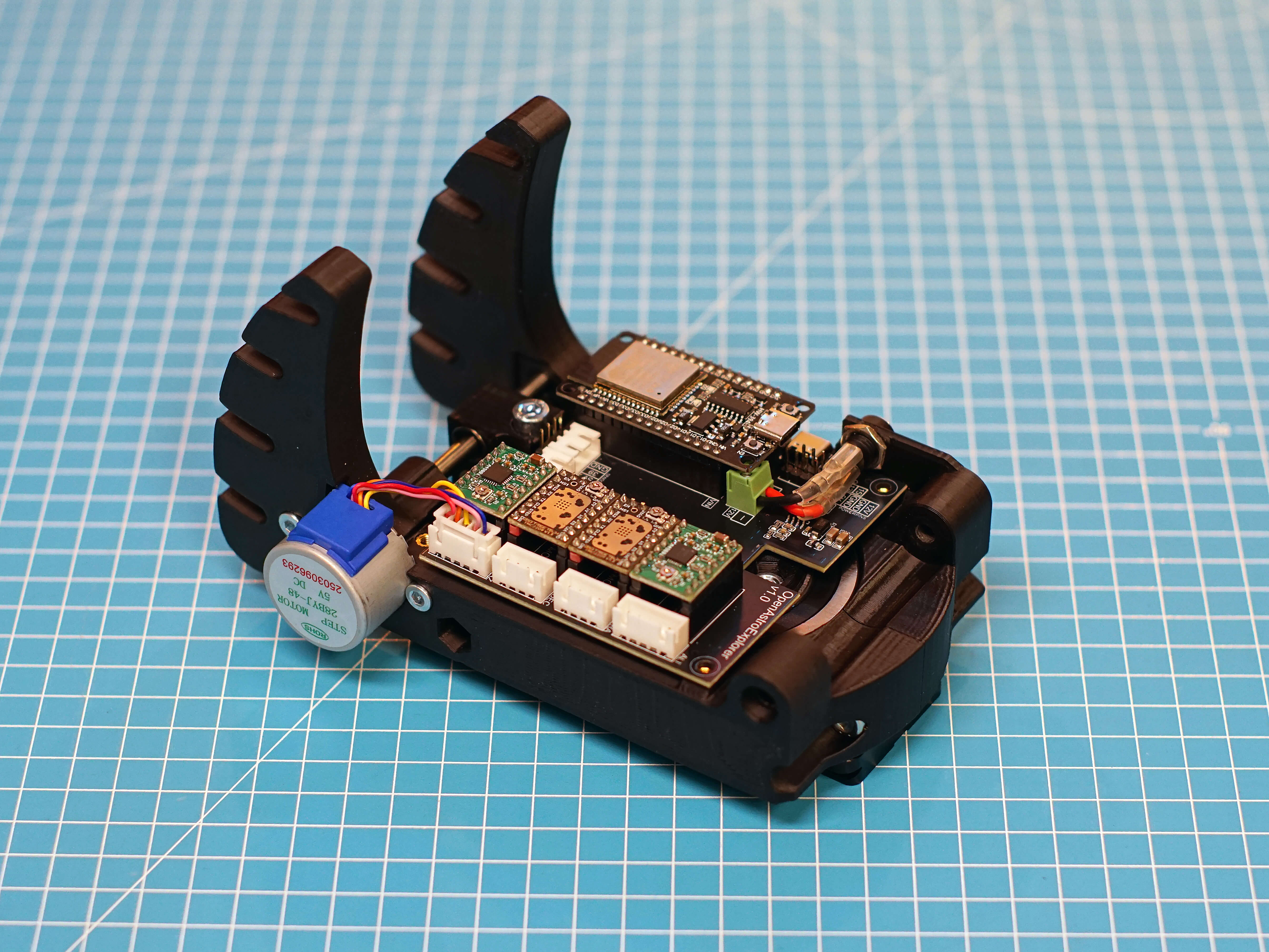
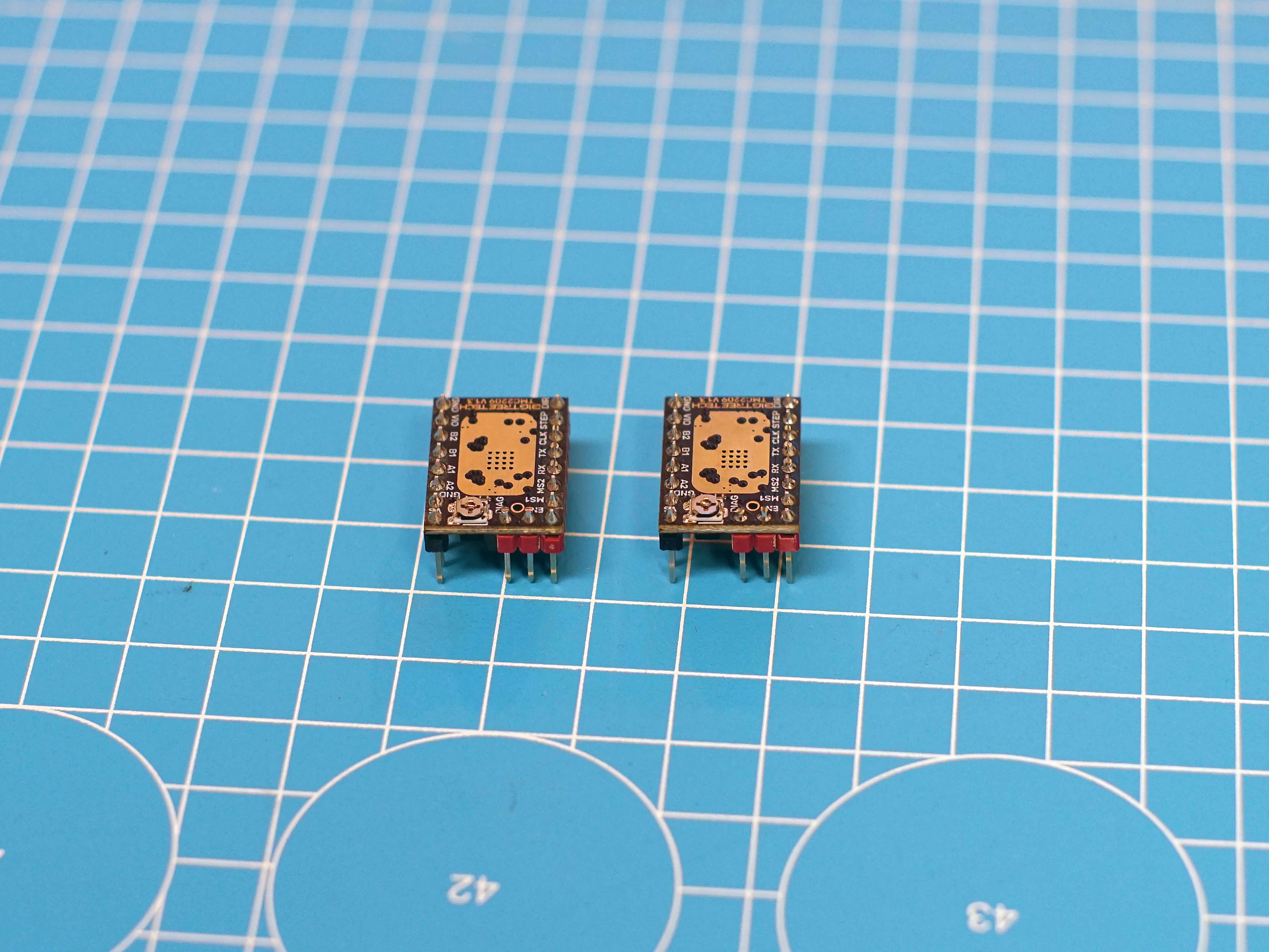
Take the 2 TMC2209 and clip off all pins on its top side with a sidecutter. You can also carefully try break them off with pliers.
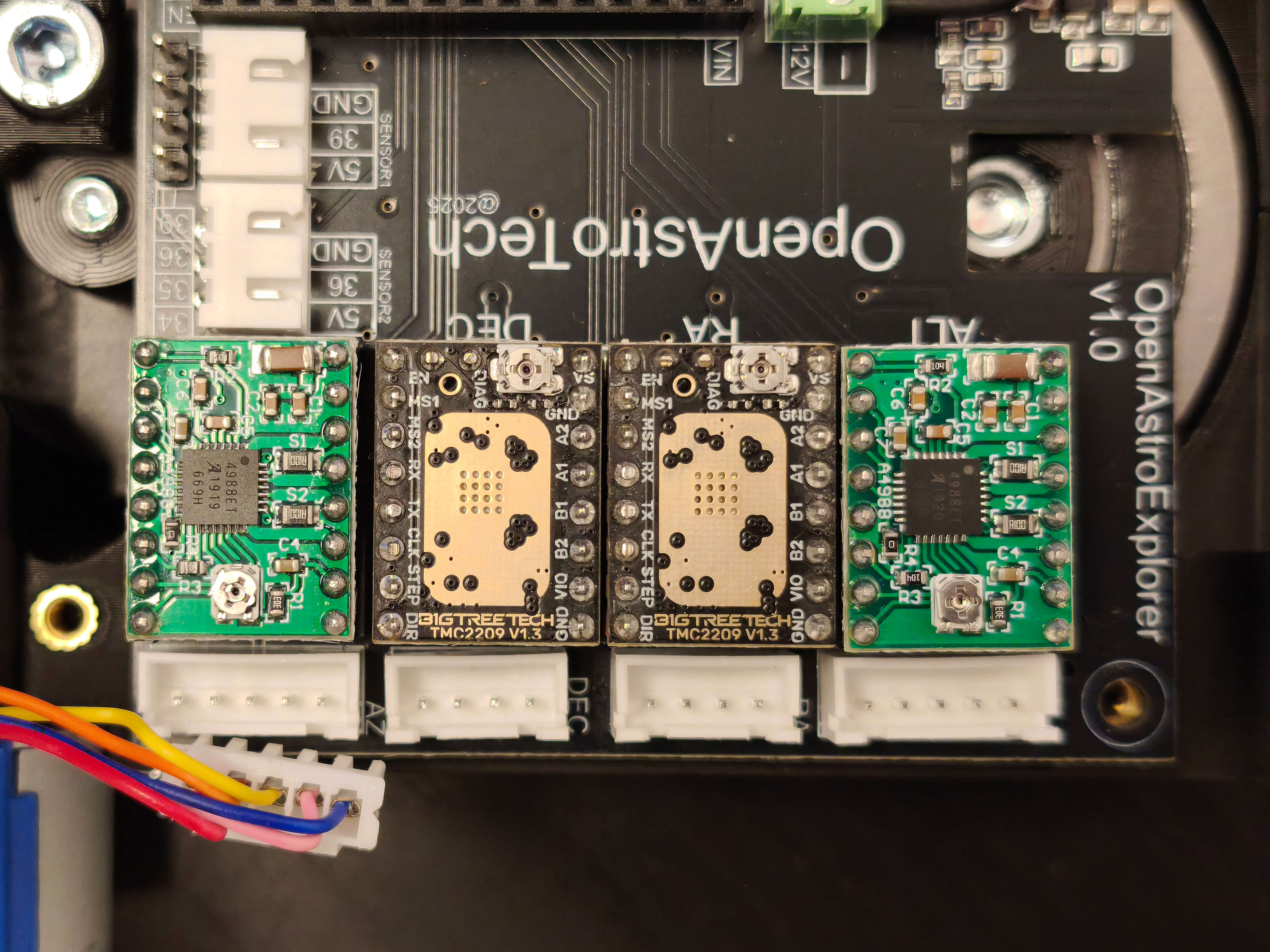
¶ Step 48
Place the drivers. TMC2209 for RA and DEC, A4988 for ALT and AZ. Pay attention to the orientation, the TMC and A4988 have the potentiometer on different sides, so it looks like they are plugged the wrong way. This is how it must look like:
- Assembly
- Parts
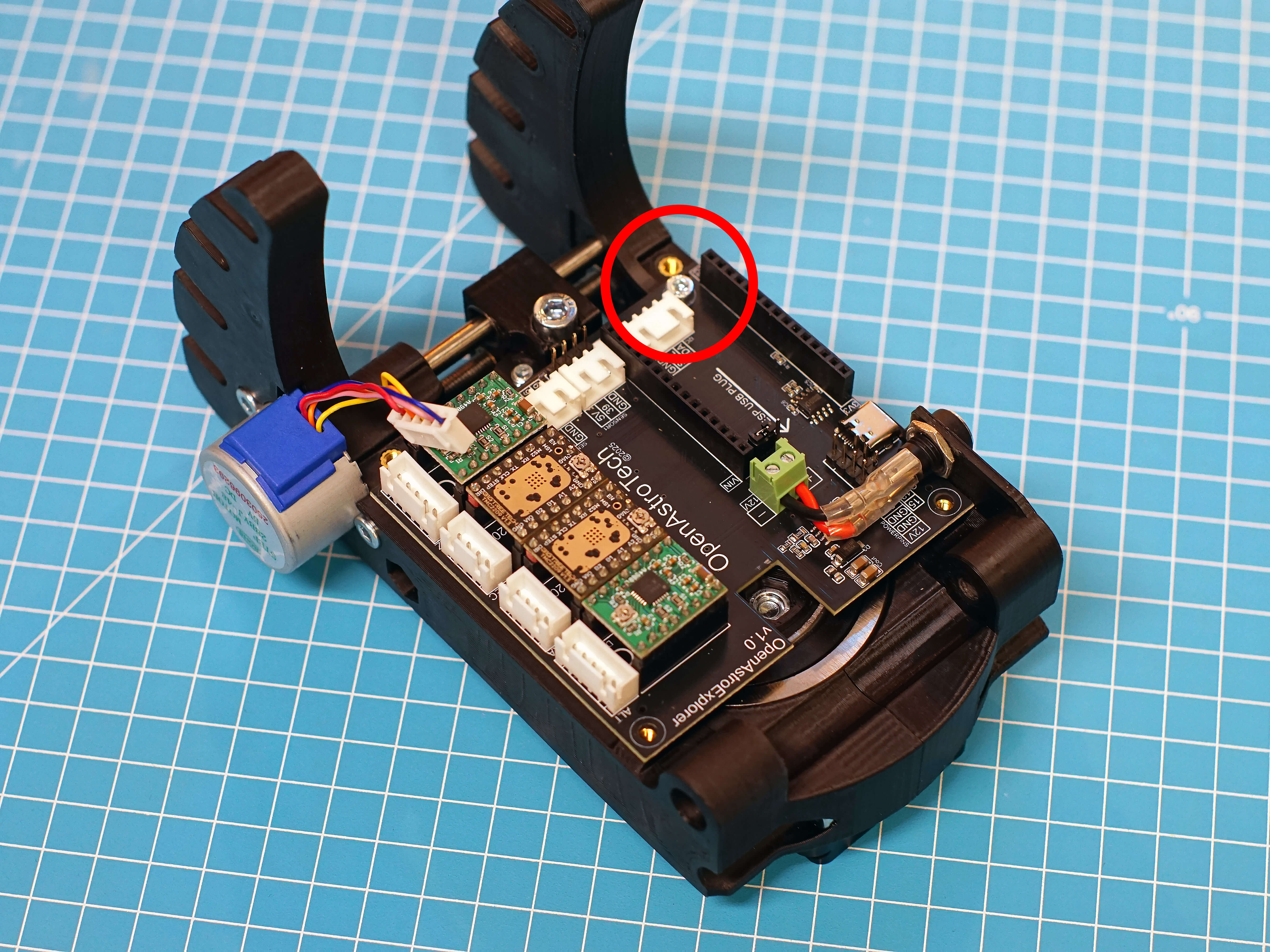
- Place the PCB on the AZ base. Connect the power cables, into the terminal connector. The PCB has the polarity printed on it. Red goes in +, black goes in -.
- Close the terminal with a small screwdriver. Make sure there are no strands of wire sticking out.
- Line up the holes on the PCB with the inserts. Attach the PCB with a M3x8 on the rear hole, circled red.
¶ Hardware
- M3x8
¶ Step 49
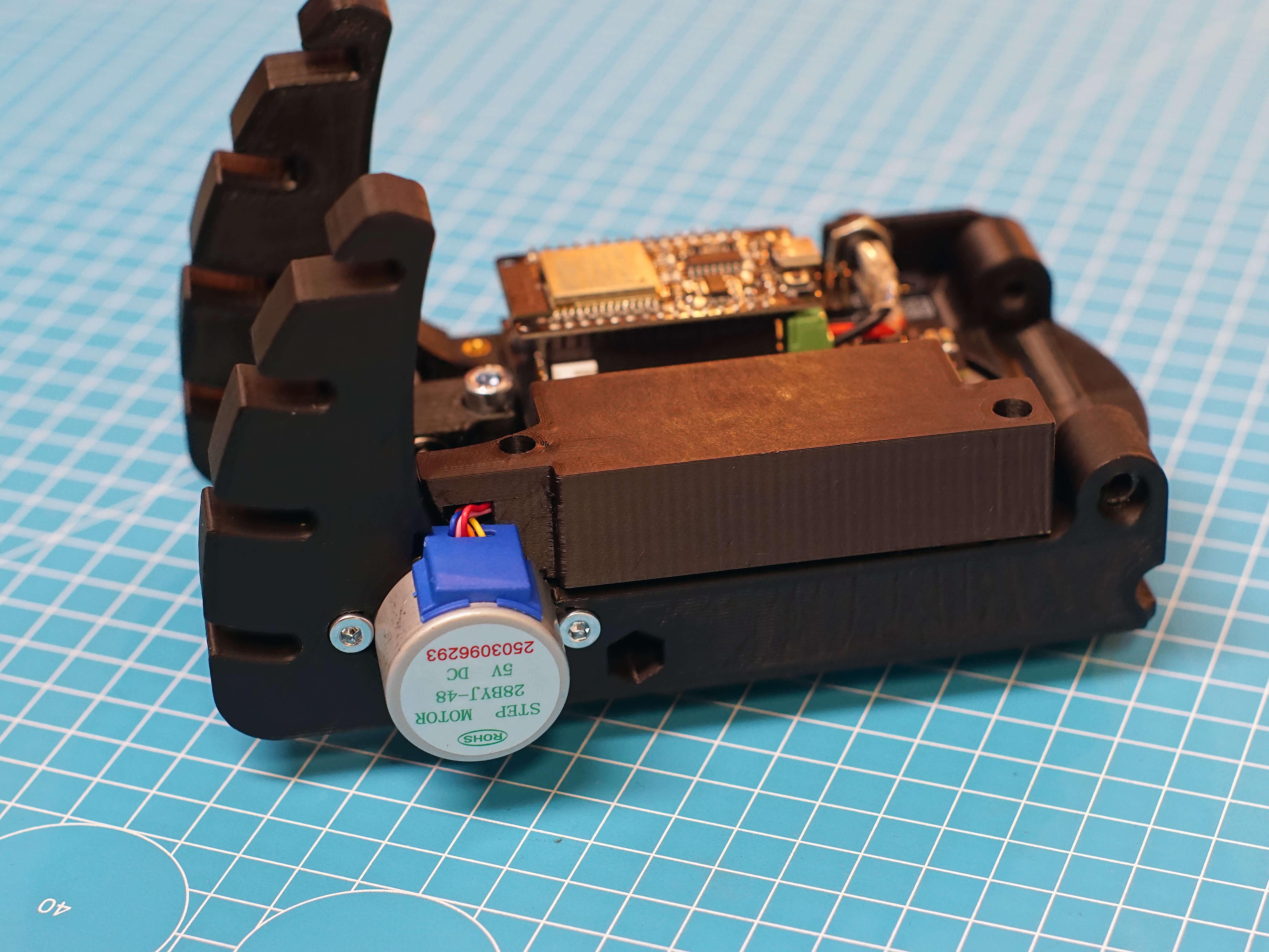
Plug in the AZ stepper into the leftmost plug, labeled AZ. Briefly take the driver_lid and put it on. The cable has to go into the little channel. Make sure it fits once, then remove the lid again. This makes sure the cable is already in shape to assembly becomes easier at a later step.
Now is also a good time to plug in the ESP32, if you have already flashed it. It can also be plugged in at a later stage, but this way you can test the AZ mechanism already.
OAE Assembly Part 1: RA Gearbox
OAE Assembly Part 2: Base
OAE Assembly Part 3: DEC
OAE Assembly Part 4: AZ Base
OAE Assembly Part 5: ALT and Final Assembly
OAE Additional Assembly