¶ Navigation
OAE Assembly Part 1: RA Gearbox
OAE Assembly Part 2: Base
OAE Assembly Part 3: DEC
OAE Assembly Part 4: AZ Base
OAE Assembly Part 5: ALT and Final Assembly
OAE Additional Assembly
¶ OpenAstroExplorer Assembly Part 3: DEC
In this step:
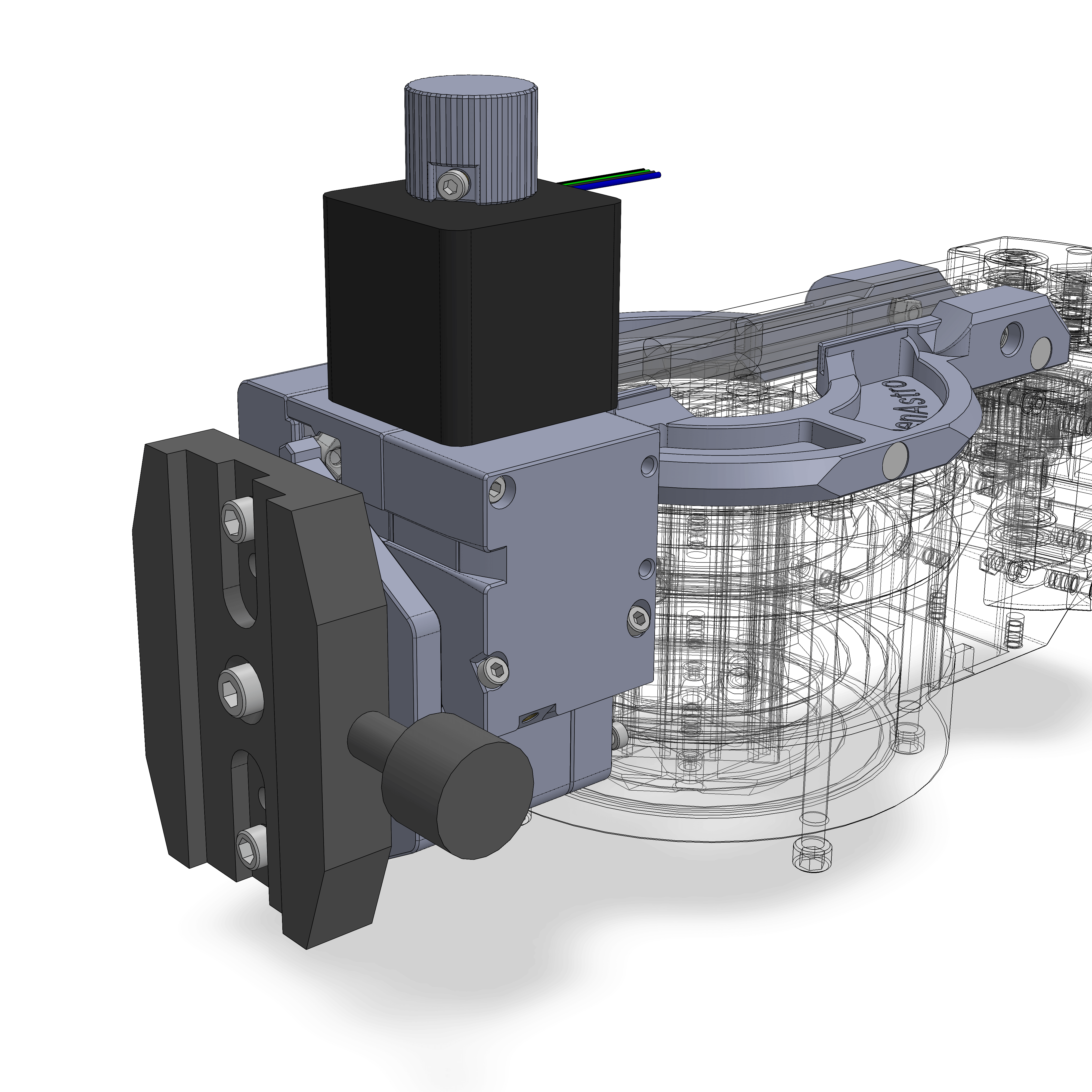
¶ Step 19
- Assembly
- Parts
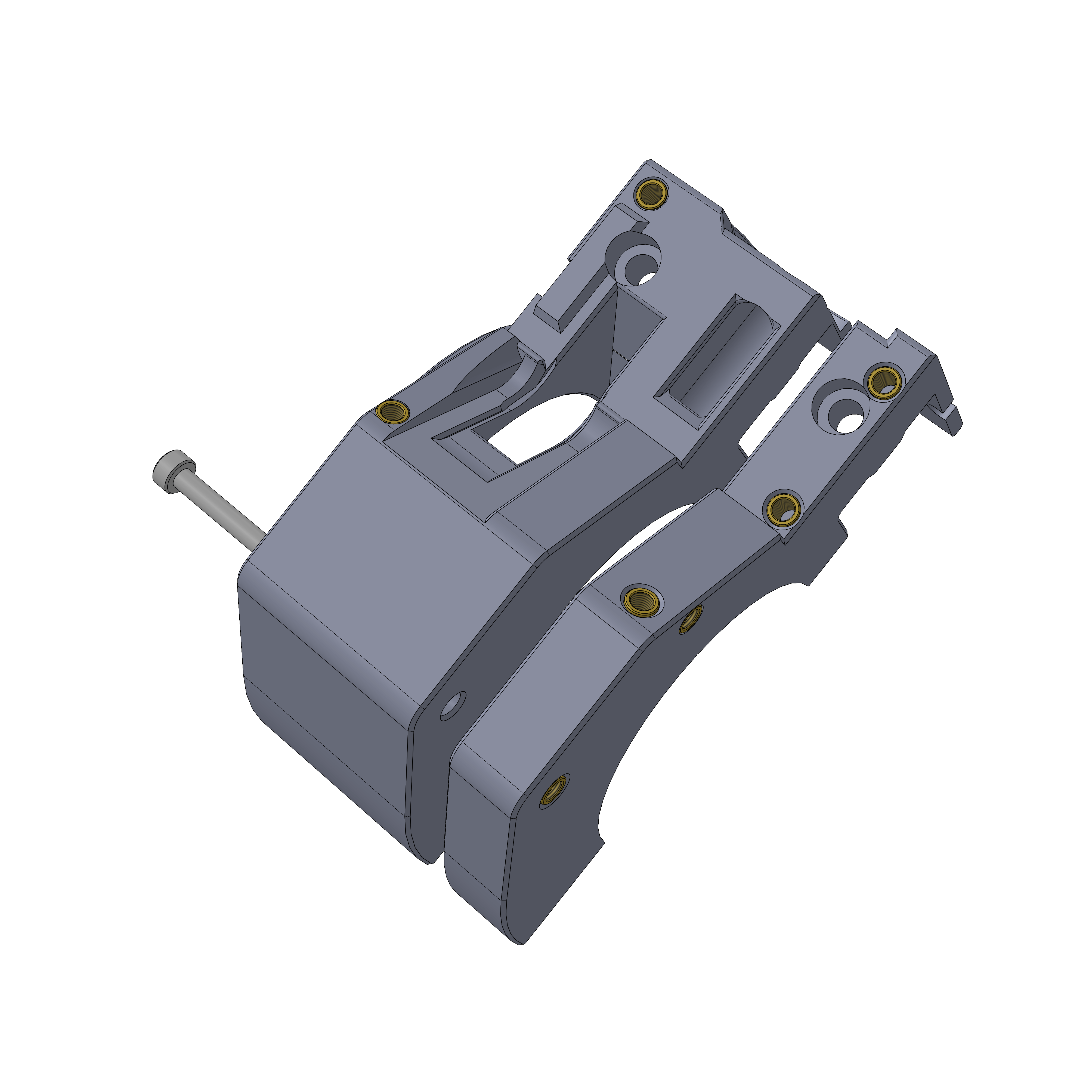
- Insert the M3x35 as shown. It should screw roughly halfway into the insert on the other side.
¶ Step 20
- Assembly
- Parts
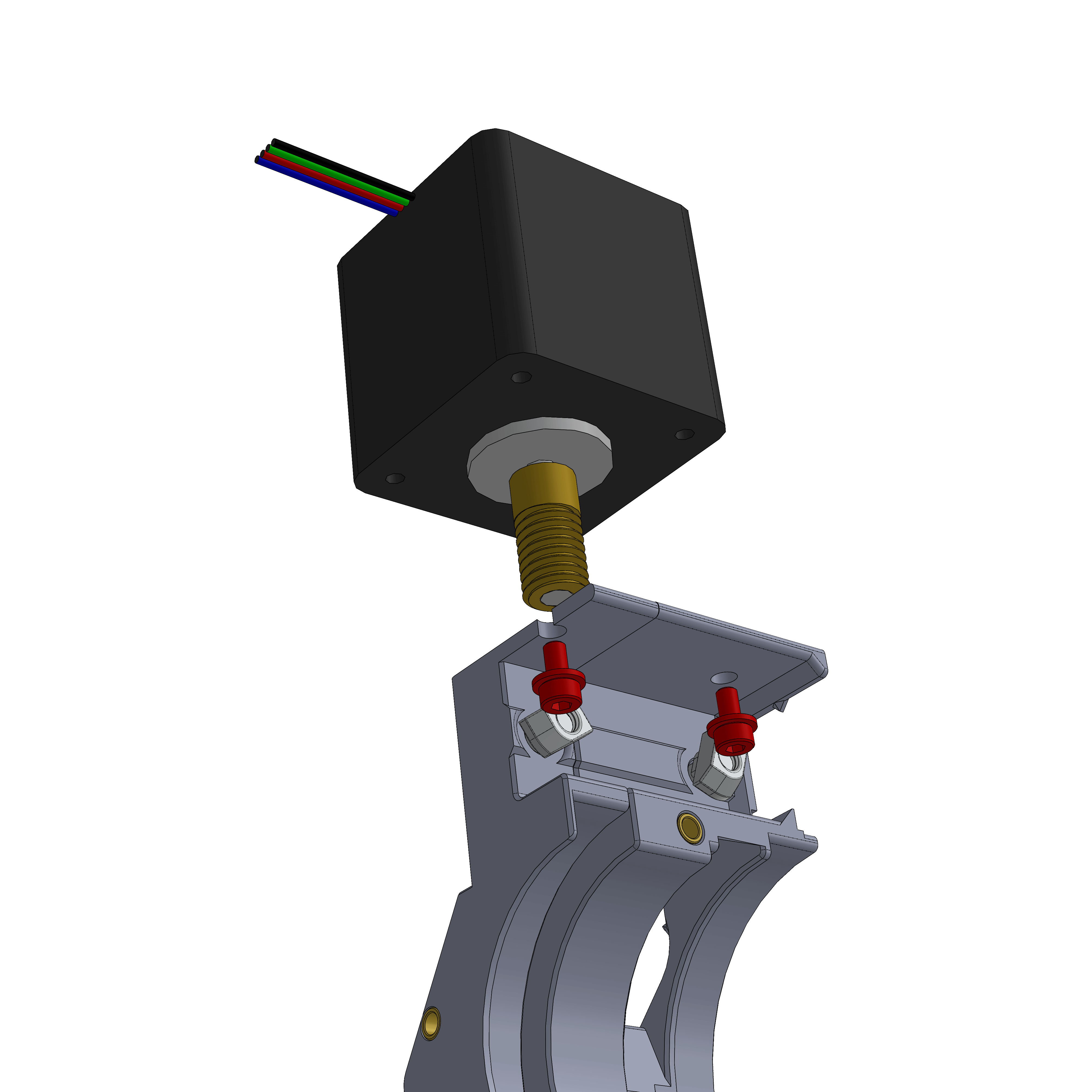
- Attach the DEC stepper, this is the dual shaft one. Attach the worm screw to it first, but don't tighten its grub screw yet.
- Place the worm screw towards the bottom of the cutout, so rather at the end of the stepper shaft. It should not touch the printed part however. Tighten its grub screw.
- Note the orientation of the wire side.
- Also attach 2 M4x12 and TNuts.
¶ Hardware
- NEMA17 Dual Shaft
- Worm screw
- 2x M3x6
- 2x M3 washer
- 2x M4x12
- 2x M4 TNut
¶ Step 21
- Assembly
- Parts
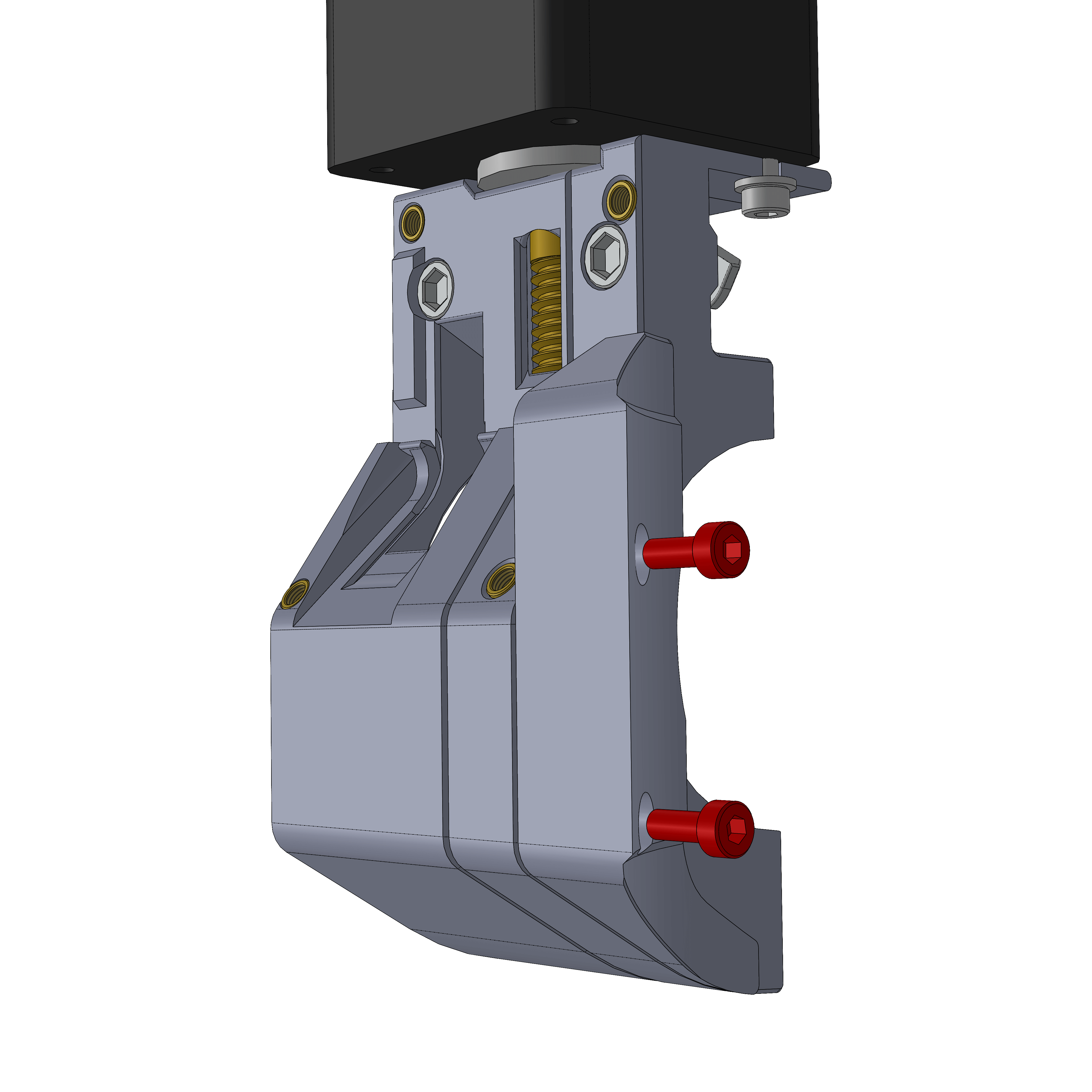
- Attach the cover. Make sure it's flush against the other part.
¶ Step 22
- Assembly
- Parts
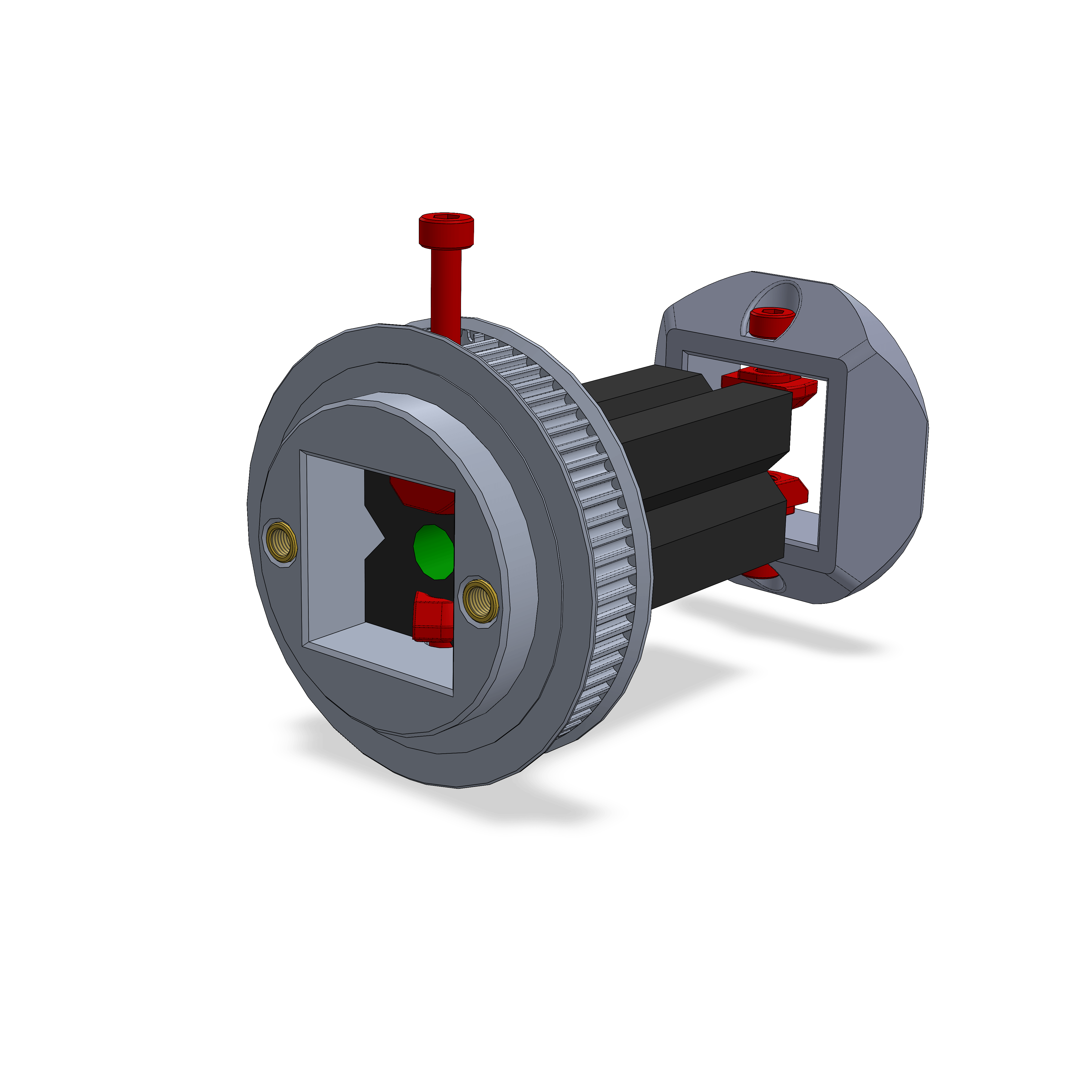
- Insert the M3x12 into the 72T Pulley and the M3x8 into the mid holder. Attach M3 TNuts to the screws.
- The threaded side of the 2020 extrusion is marked green here. Note the orientation of the parts.
- Don't tighten the screws yet.
¶ Step 23
- Assembly
- Parts
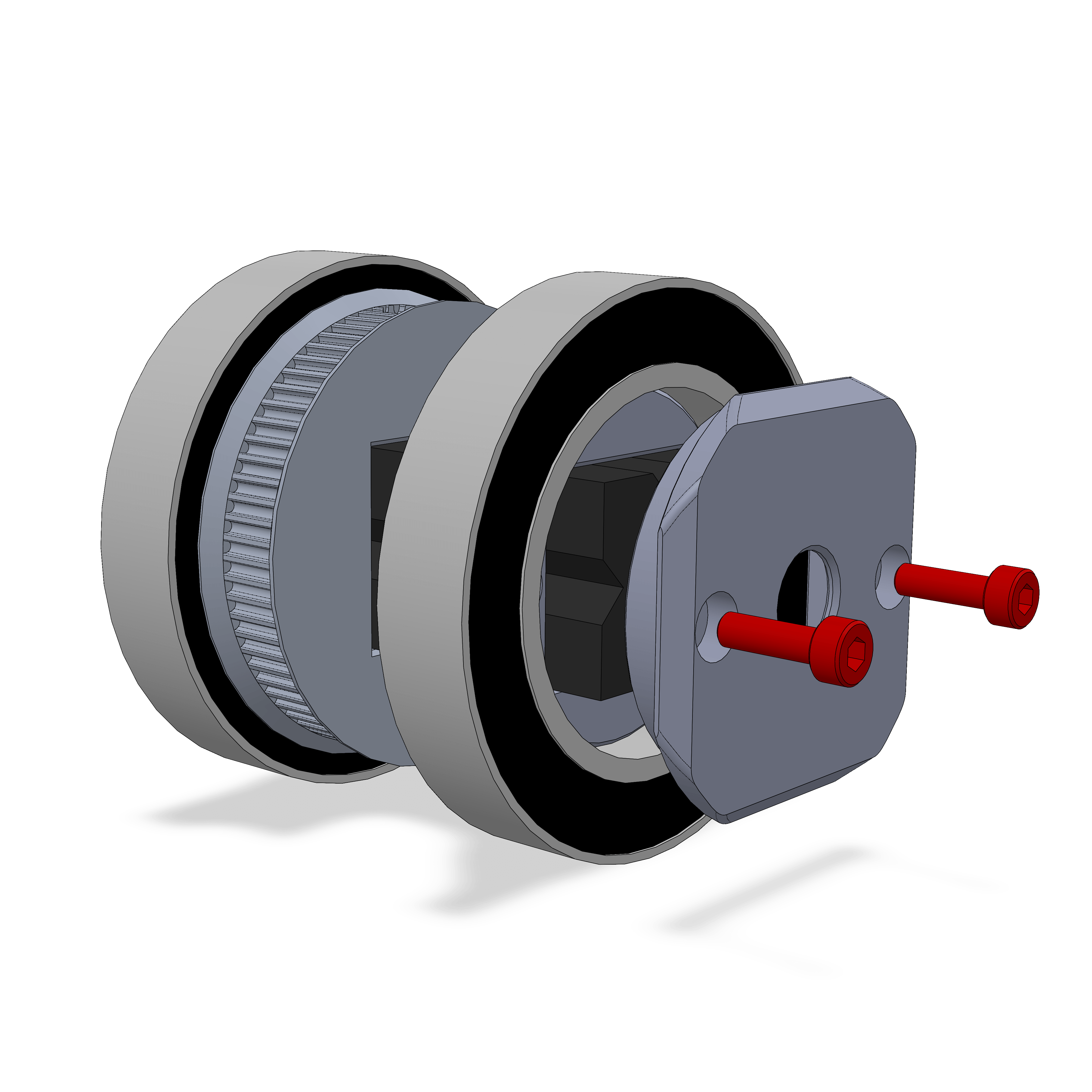
- Attach the rear adapter, make sure the screws align with the inserts. Slide the mid adapter so that the rear one is flush against the end of the extrusion. Tighten the M3 screws with the TNuts but only for the rear part. The 72T pulley should still be able to slide.
¶ Step 24
- Assembly
- Parts
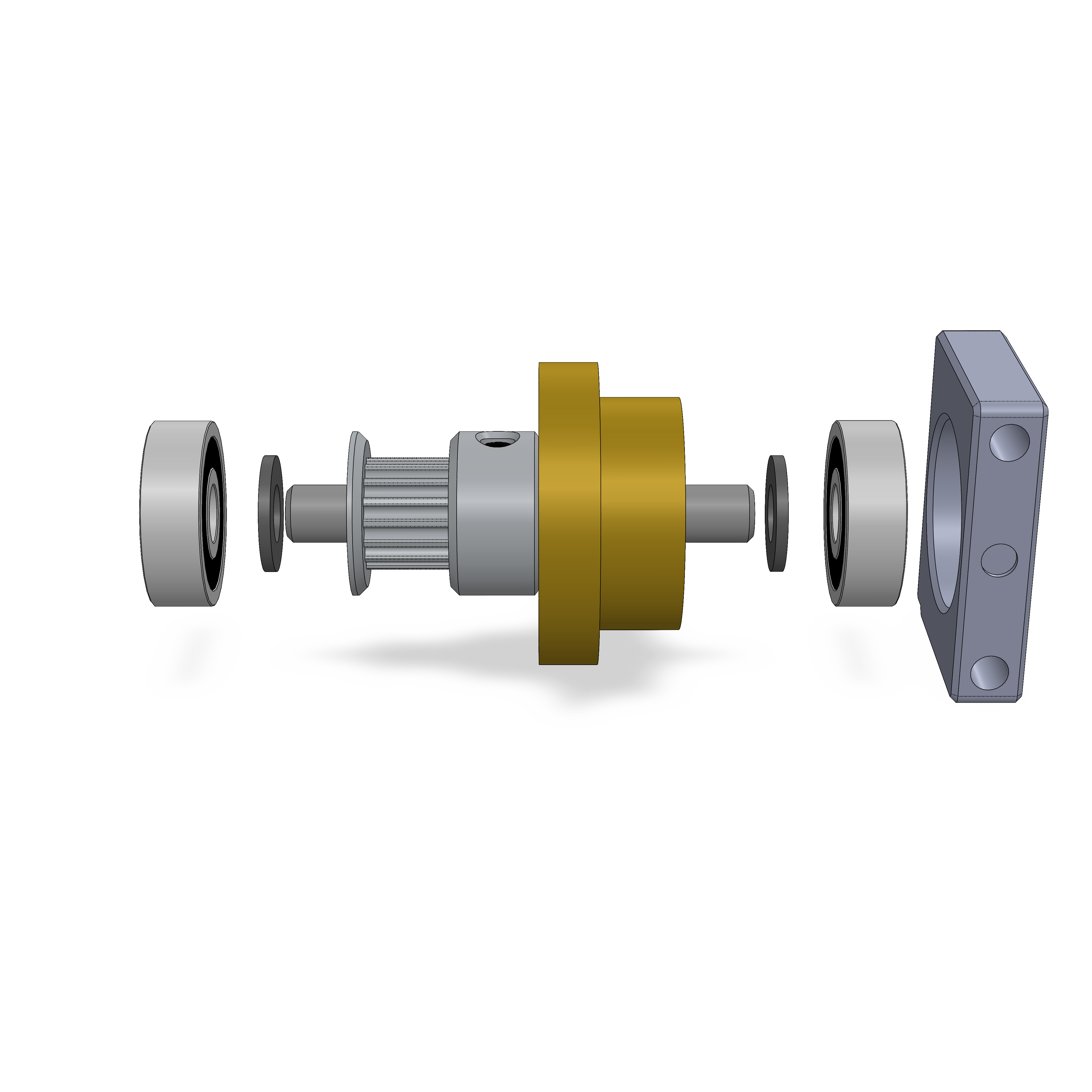
- Attach all parts as shown. In the end, the bearings should be flush with the ends of the shaft. Note: Some worm wheels can be shorter than this. Assemble the shaft from the pulley side and seat the worm wheel flush with the pulley as shown. It can be that there will be a large gap to the right side bearing, in which case leave the shim away.
- Tighten the grub screws good, especially the single one on the worm wheel can slip easily.
¶ Step 25
- Assembly
- Parts
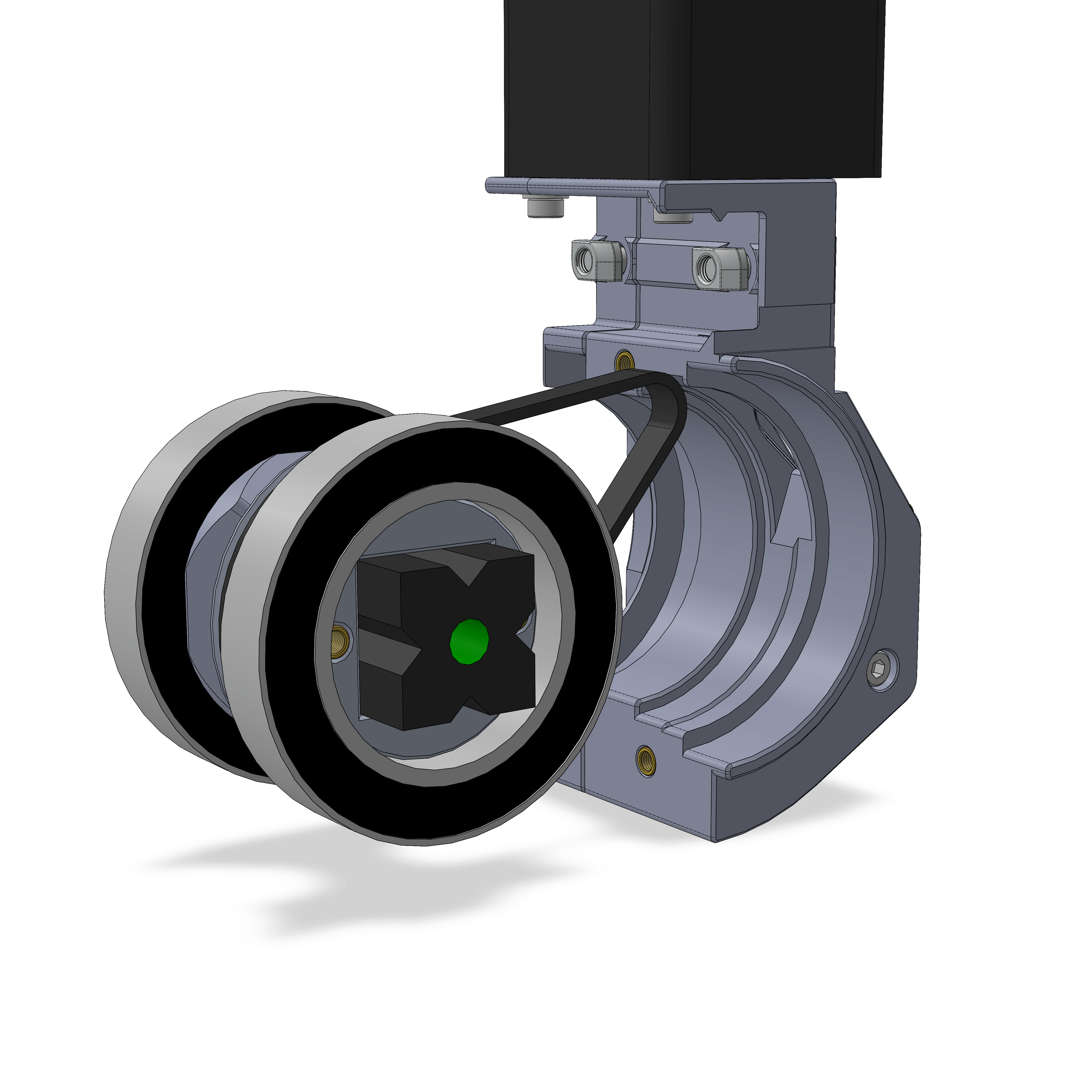
- Insert the assemblies as shown. Put the belt around the 72T pulley and then through the slot.
- Arrange the 72T pulley so its bearing fits well into its slot. Make sure the front bearing is firmly touching the part towards the rear side.
- Then also tighten its M3 screws.
¶ Hardware
- GT2 192mm 96T belt
¶ Step 26
On the base assembly, rotate the inner part so that the larger cutout on the bottom lines up with the stepper side of the mount.
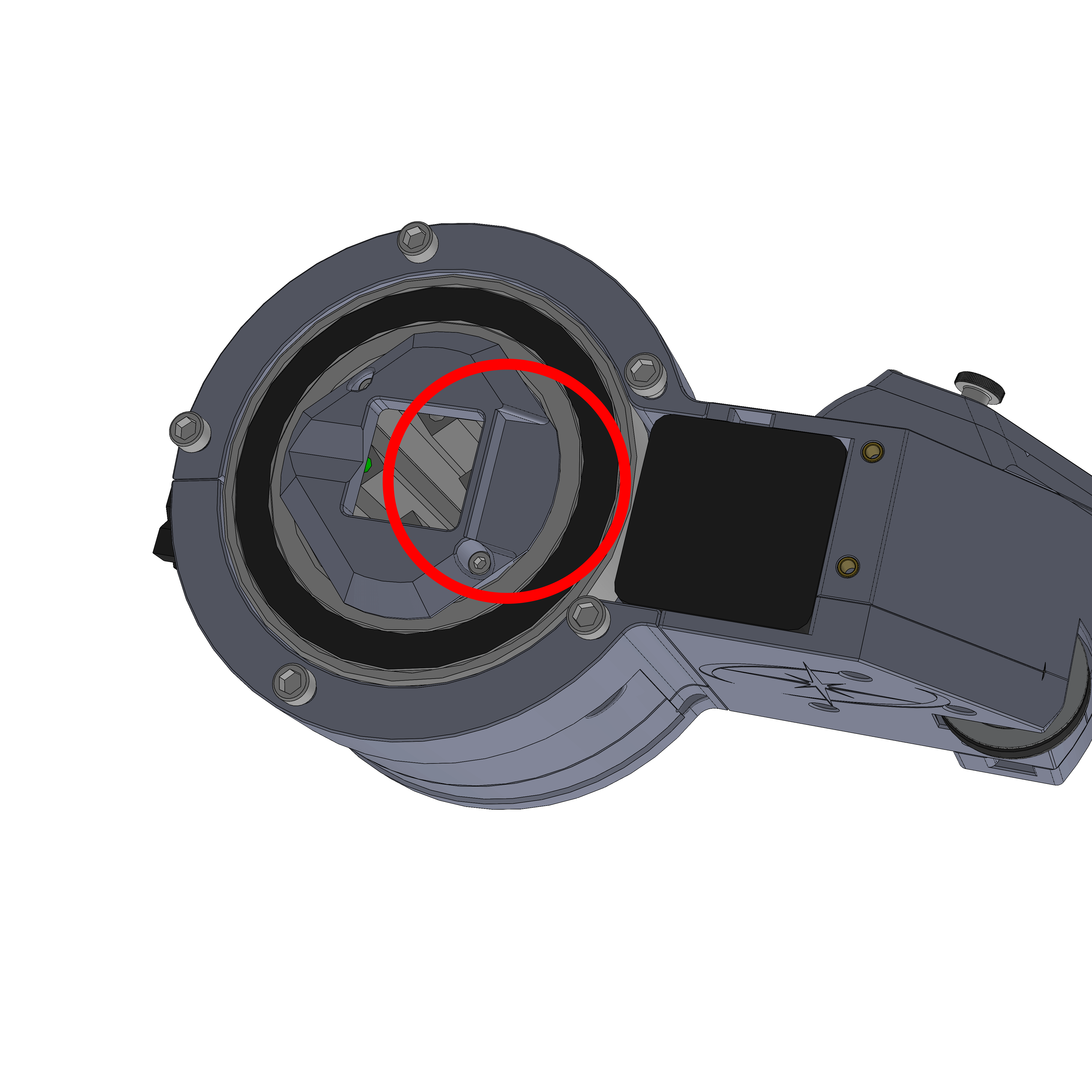
Now attach the DEC assembly to the 2020 extrusion at the top.
The cover part should have at least 1mm of spacing to the base. Tighten the M4 screws (red).
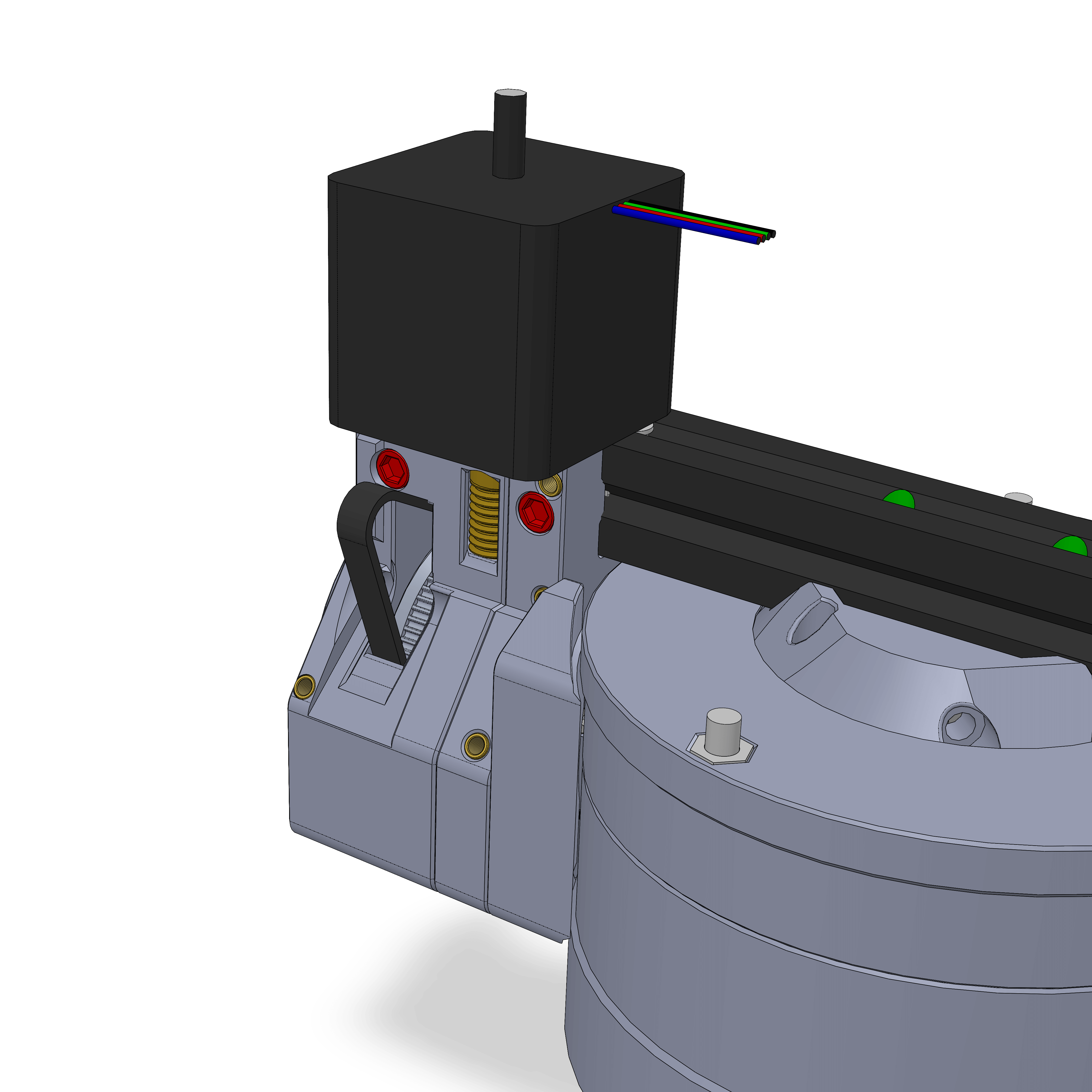
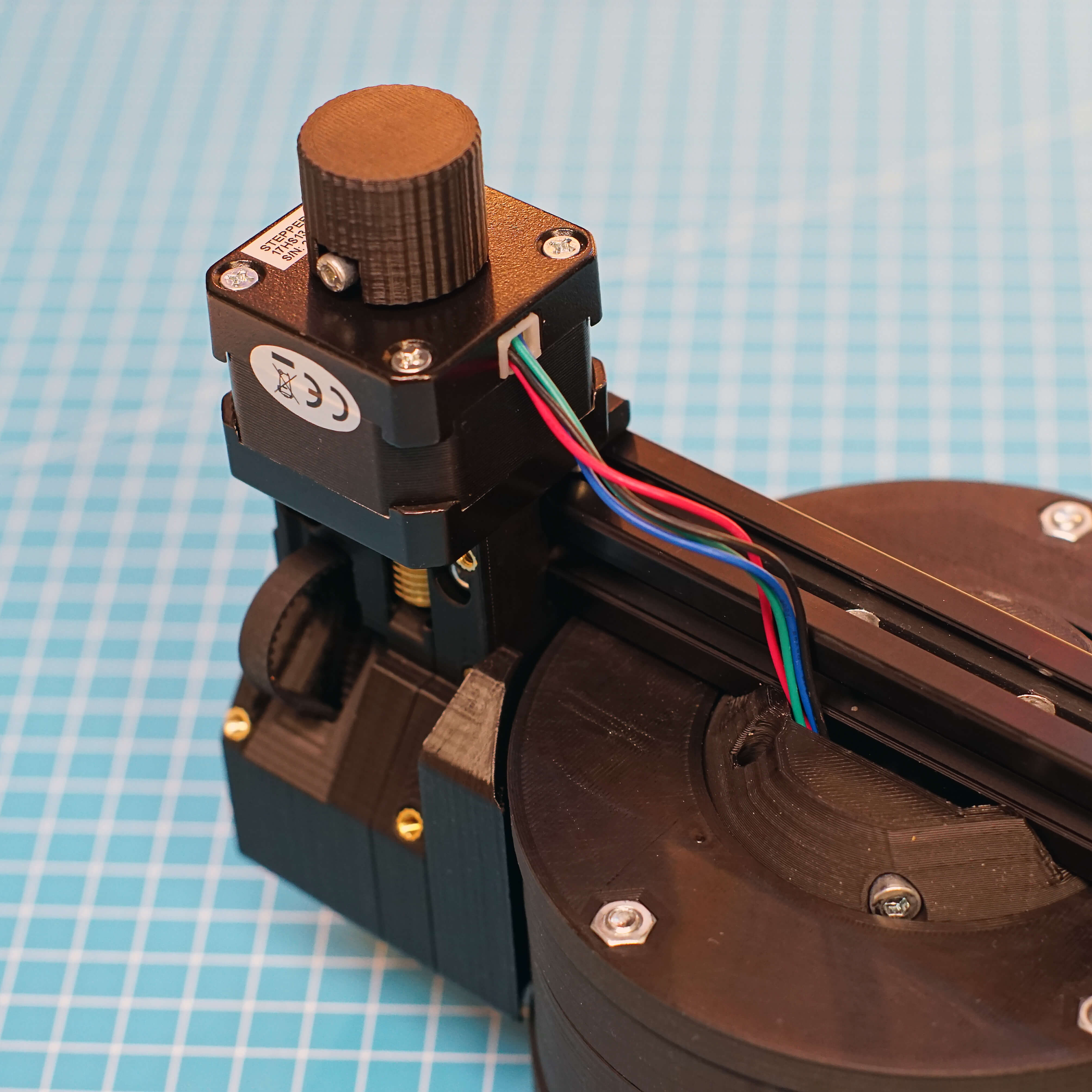
The stepper cable gets routed through the 4040 extrusion. If the JST Plug of your stepper is already attached, you'll have to detach it again in order to fit it through the printed parts.
¶ Step 27
- Assembly
- Parts
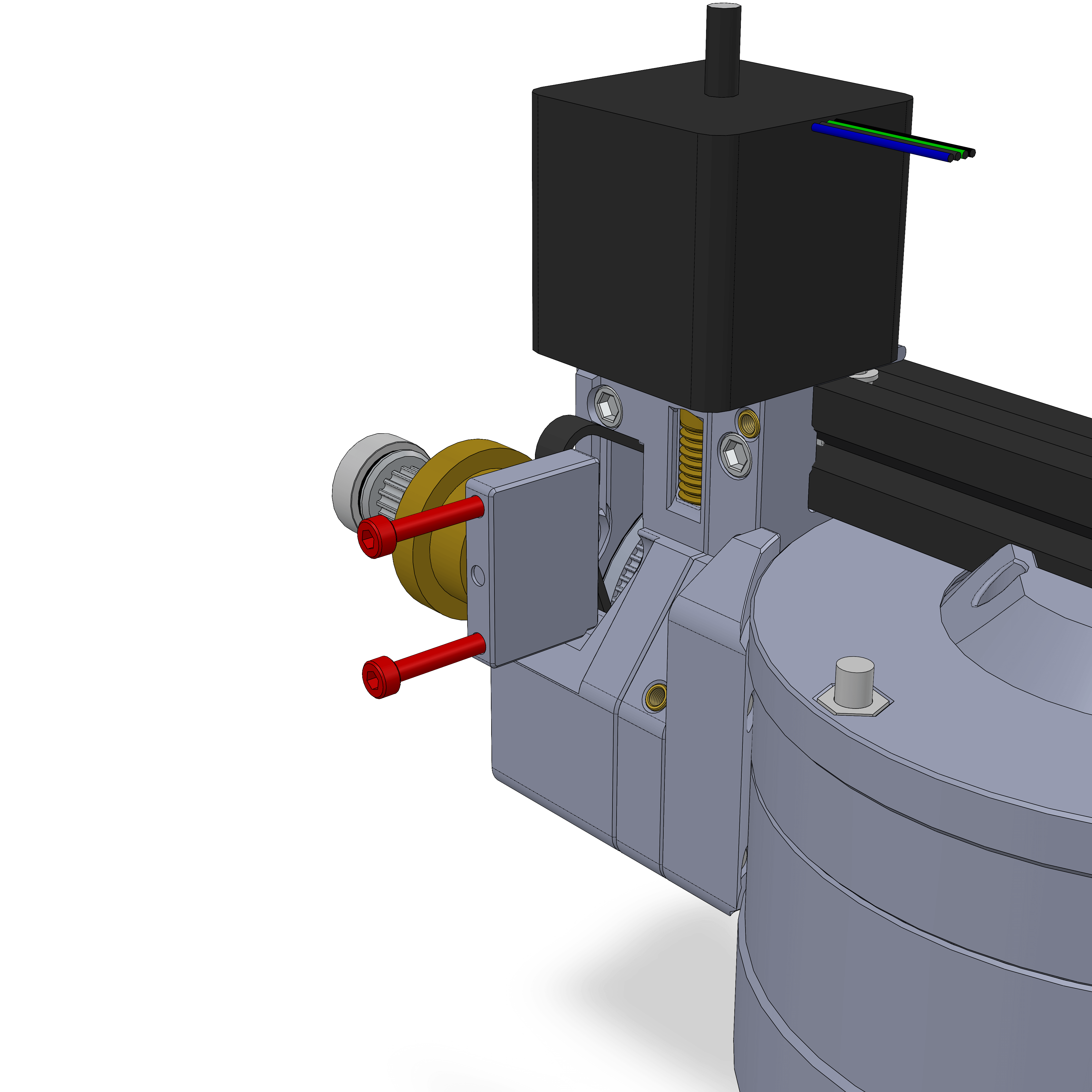
- Attach the worm gear assembly as shown. Note the little circular indent, it should be facing you. You'll have to angle it in, so that you can attach the belt around the pulley.
- Only very loosely tighten the 2 M3 screws, maybe a few turns. These should NEVER be anywhere close to being tight. They are used to set the preload on the worm gear, so tightening them might damage the brass gears.
¶ Hardware
- Assembly from Step 24
- 2x M3x25
¶ Step 28
- Assembly
- Parts
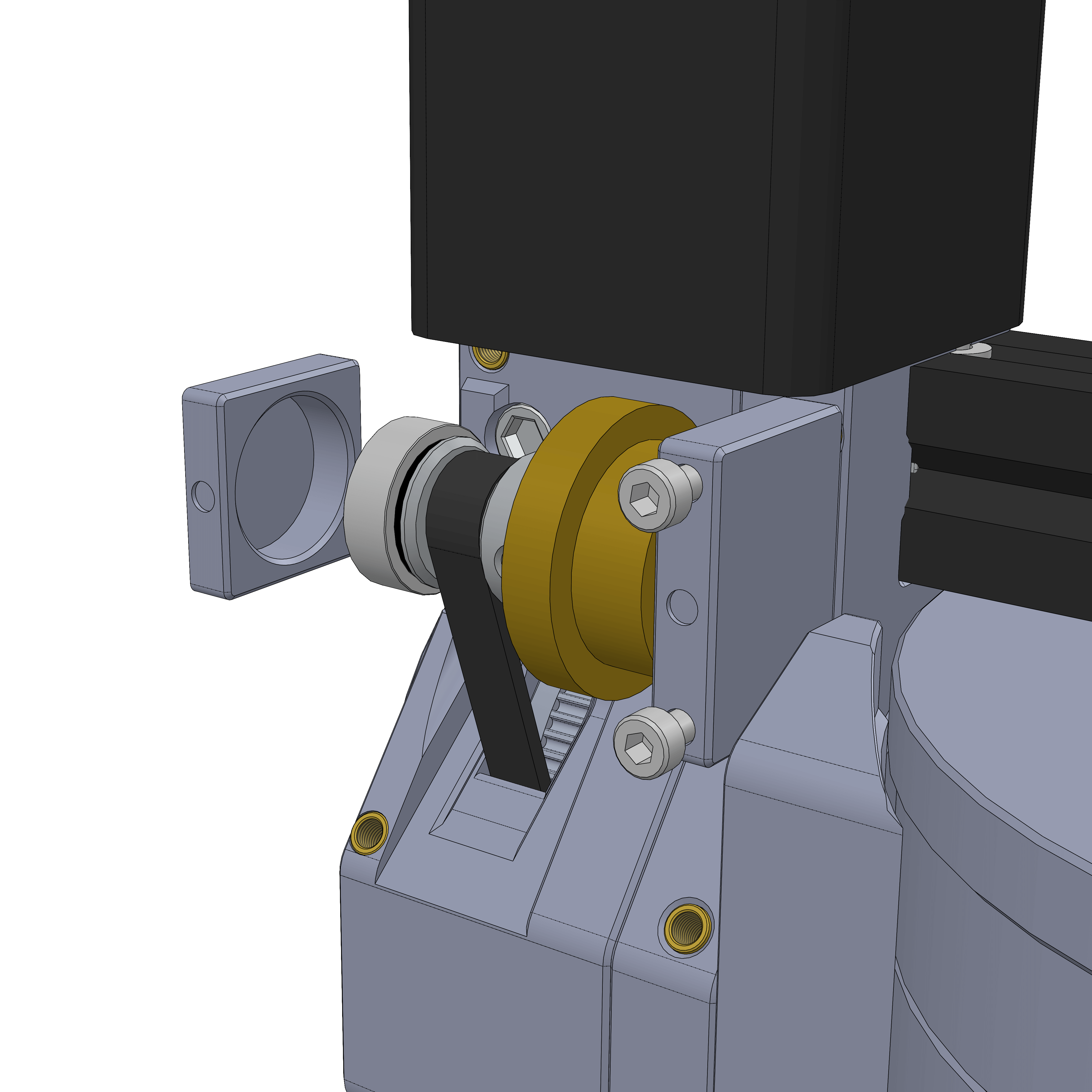
- Attach the other bearing holder.
- The worm (the part attached to the stepper) can come in different sizes, usually 10 or 12mm diameter. Depending on which size you have, rotate the bearing holder 180°. One side will have a little circular indent, shown here. Have this facing outwards if your worm is 12mm dia. Have the line indent facing you if you have a 10mm worm.
- Apply grease to the gears. The mechanism should not be operated without any lubrication. General purpose grease is good enough, apply a generous amount.
¶ Parts
¶ Step 29
- Assembly
- Parts
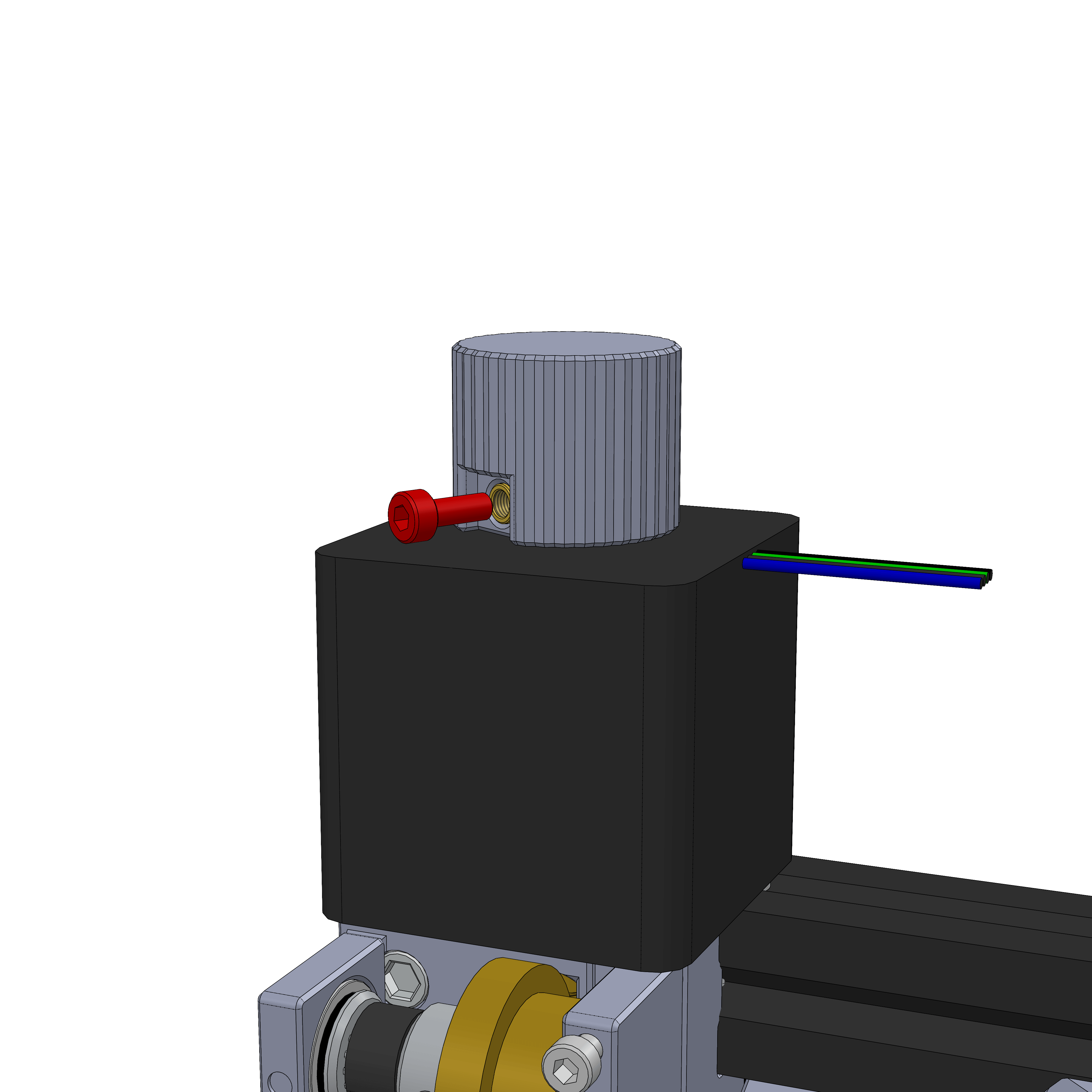
- Attach the DEC knob with a M3x8 screw. Make sure the knob turns somewhat evenly and has some spacing to the stepper.
- The knob is used to rotate the DEC axis by hand, but also to feel the preload on the worm gears.
Rotate the knob a bit and get a feel how much resistance it has with zero preload. This will help you to set it correctly later.
¶ Step 30
- Assembly
- Parts
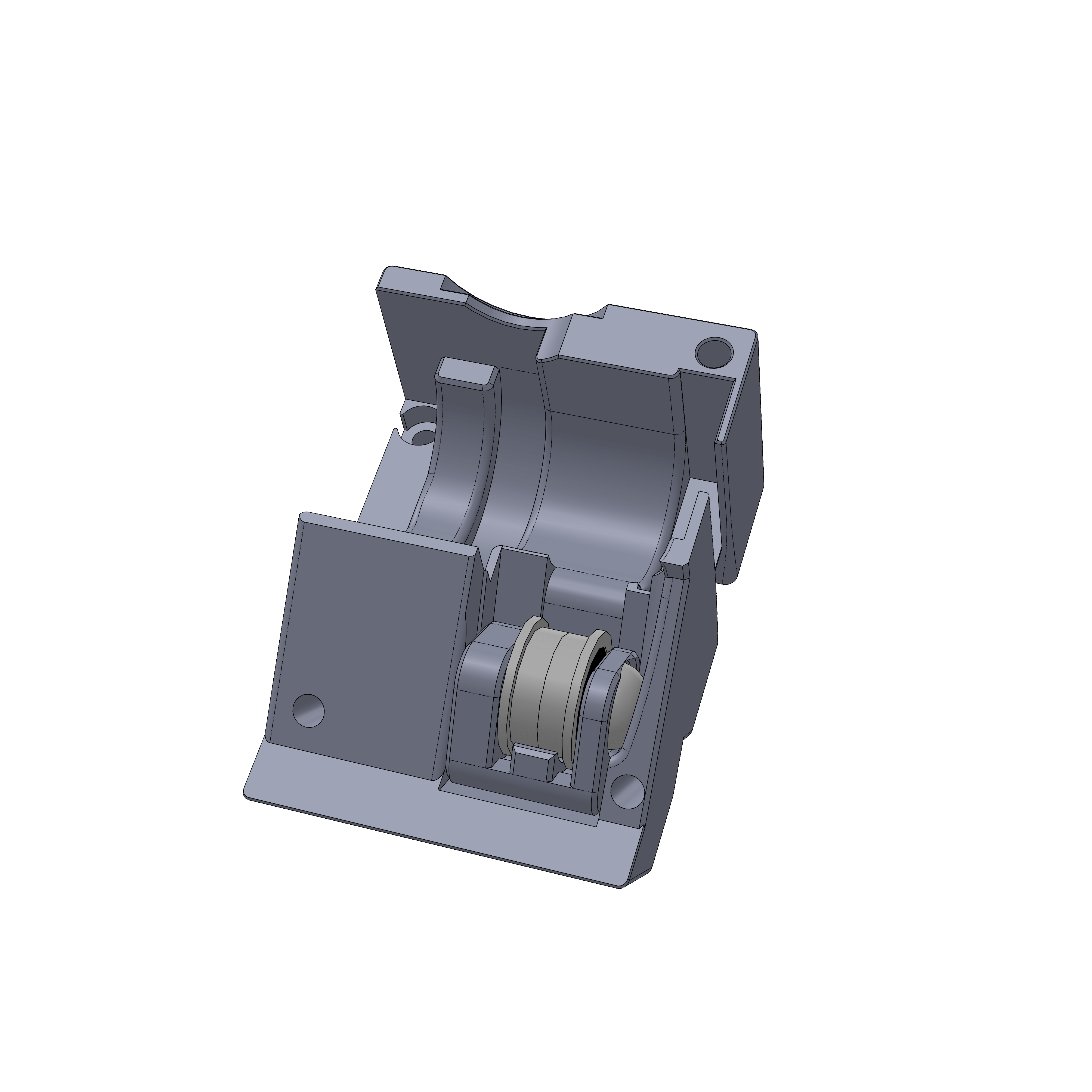
- Lay the other tensioner you built into the DEC gearbox as shown.
¶ Step 31
- Assembly
- Parts
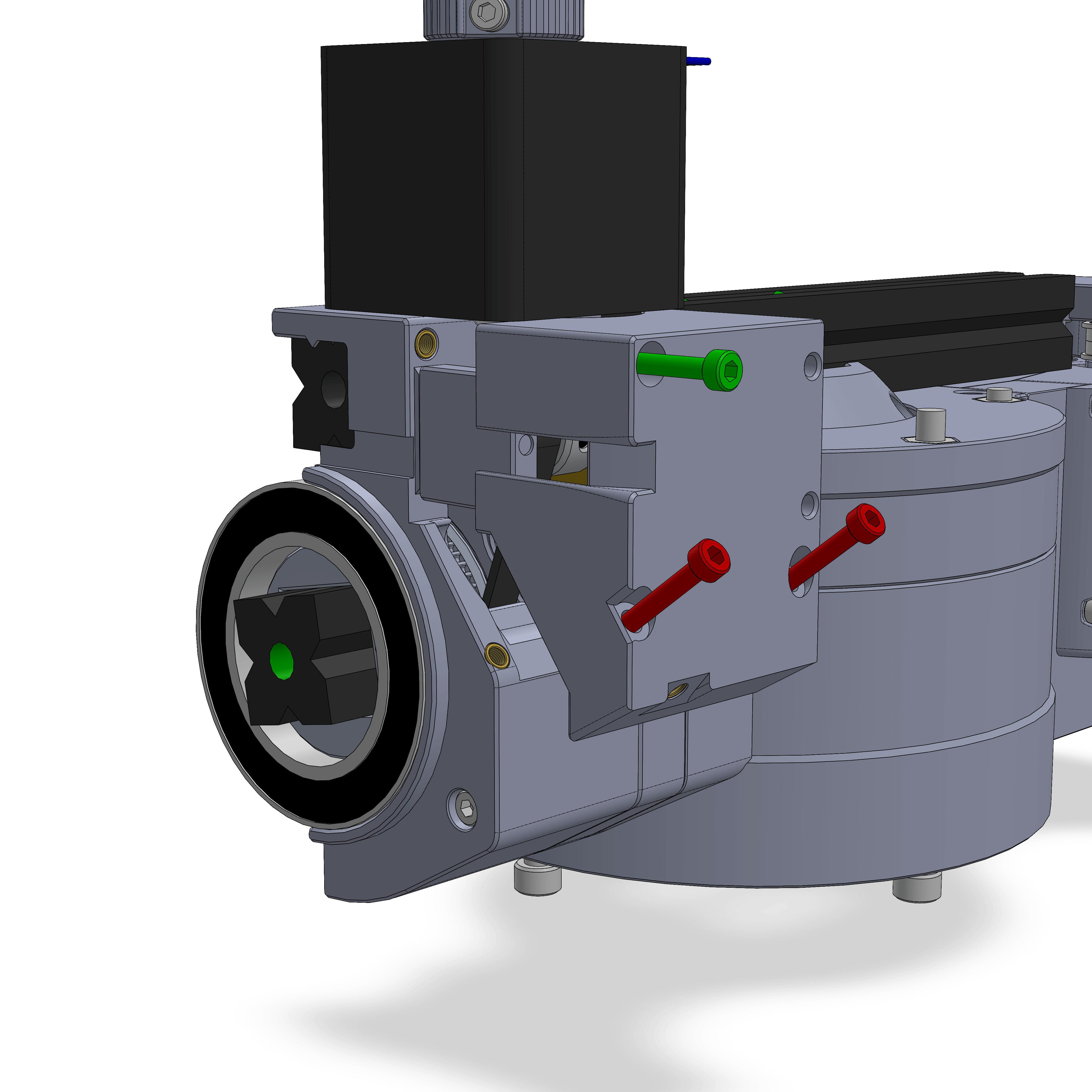
- Gently push the part on top the assembly. This might take a little bit of force.
- Check if the stepper is now significantly harder to turn. If it is, remove and attach the part again, that can sometimes help. If still not, check if there is a print defect or similar on the part that might put pressure on the worm assembly.
- It is normal that the stepper now turns slightly harder.
- Attach the 3 screws. Green is M3x30, red is M3x20. These don't get tensioned a lot.
- Check again if the stepper turns significantly harder after tightening the screws. If yes, loosed the screws a bit, or pull the part a bit outwards to relieve pressure. The stepper shouldn't turn any harder than without the screws.
¶ Hardware
- 1x M3x30
- 2x M3x20
¶ Step 32
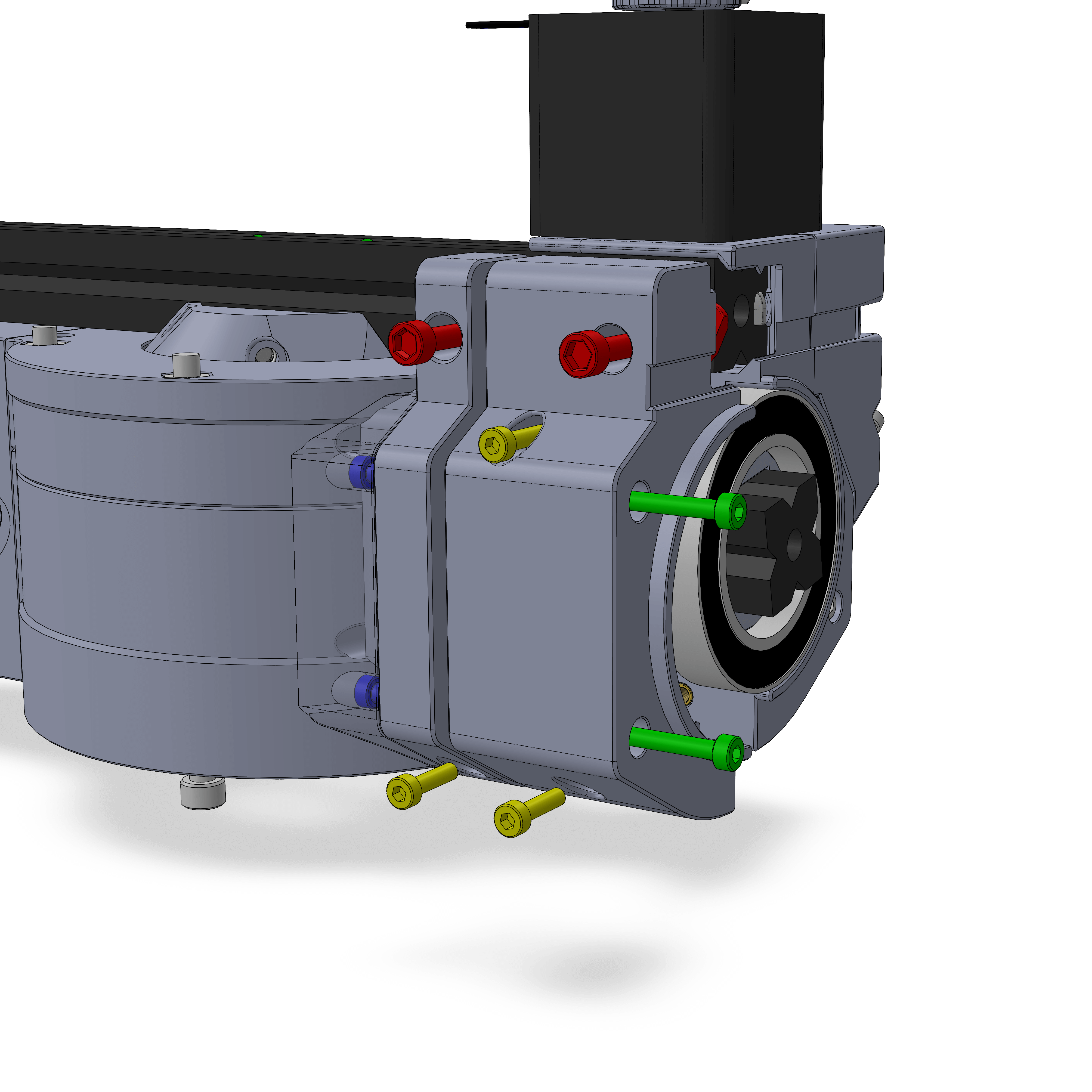
- Assembly
- Parts
- Attach the two DEC_holders with 2 M3x35 (green), then the cover with 2 M3x8 (blue).
- Insert 2 M4x12 and TNuts (red) and put the assembly as shown.
- Before tightening the M4 screws, rotate the entire RA axis and make sure the DEC is not scraping on the base, and has at least 1mm of space along the entire rotation. Then tighten the M4 screws.
- Use 3 M3x12 screws (yellow) to join the two halfes.
¶ Step 33
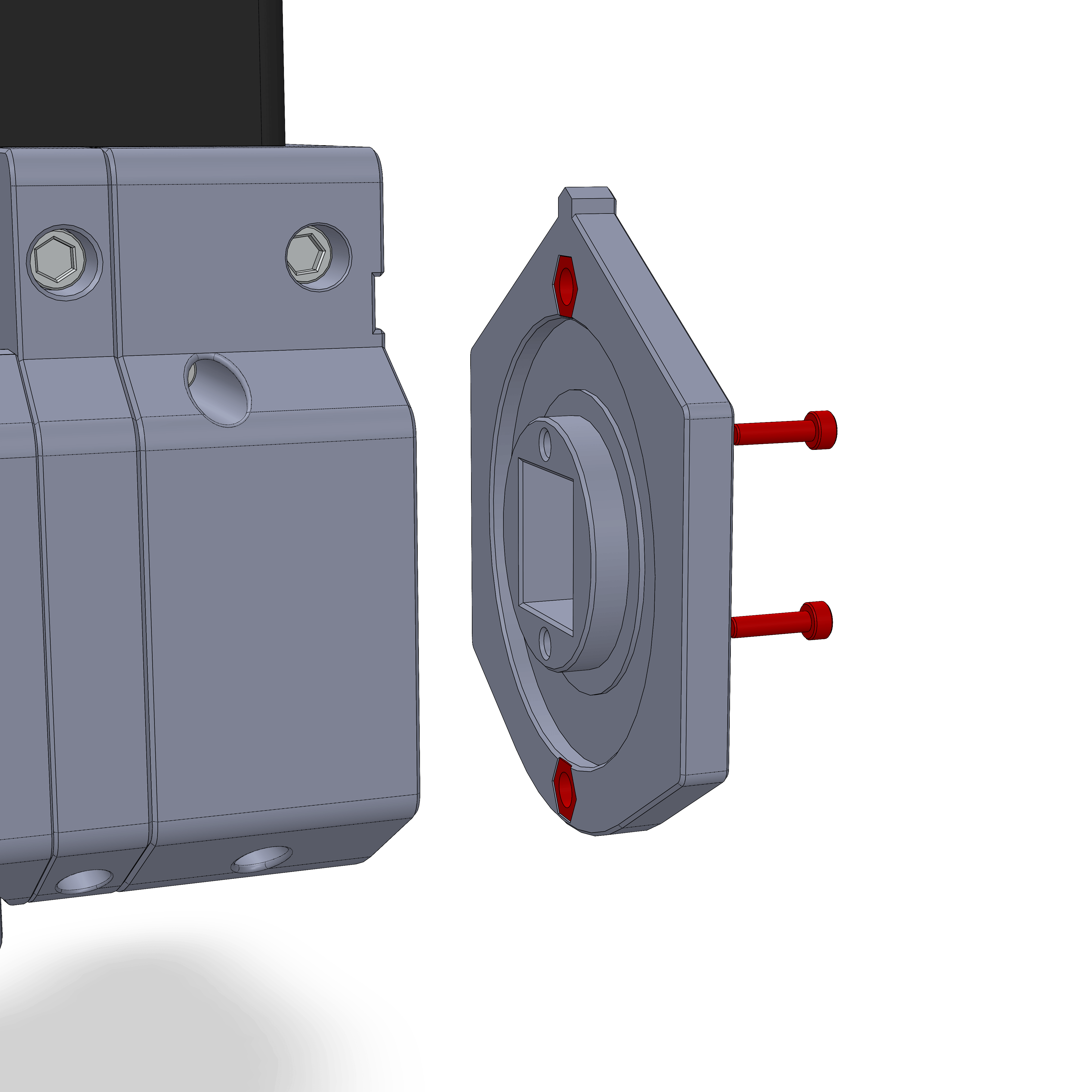
- Assembly
- Parts
- Insert 2 M5 Nuts into the DEC wheel base. Push it into the front, it is fully in when the 2020 extrusion is roughly flush with the front side.
- Tighten with 2 M3x12 screws.
¶ Step 34
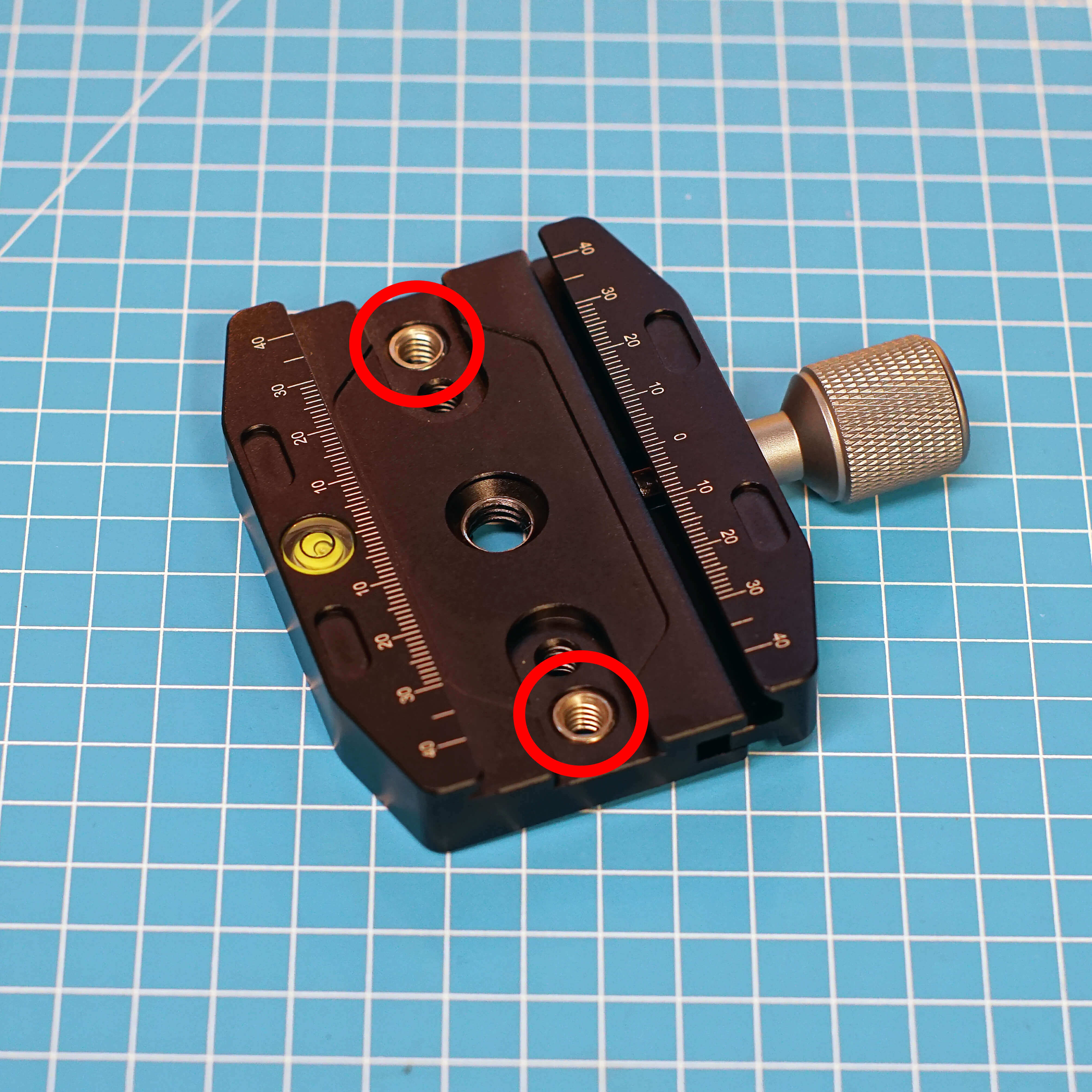
Attach two 3/8" inserts as shown. One will be in the middle of the clamp and you can take the other one from the other clamp you will have gotten. Screw them in from the bottom.
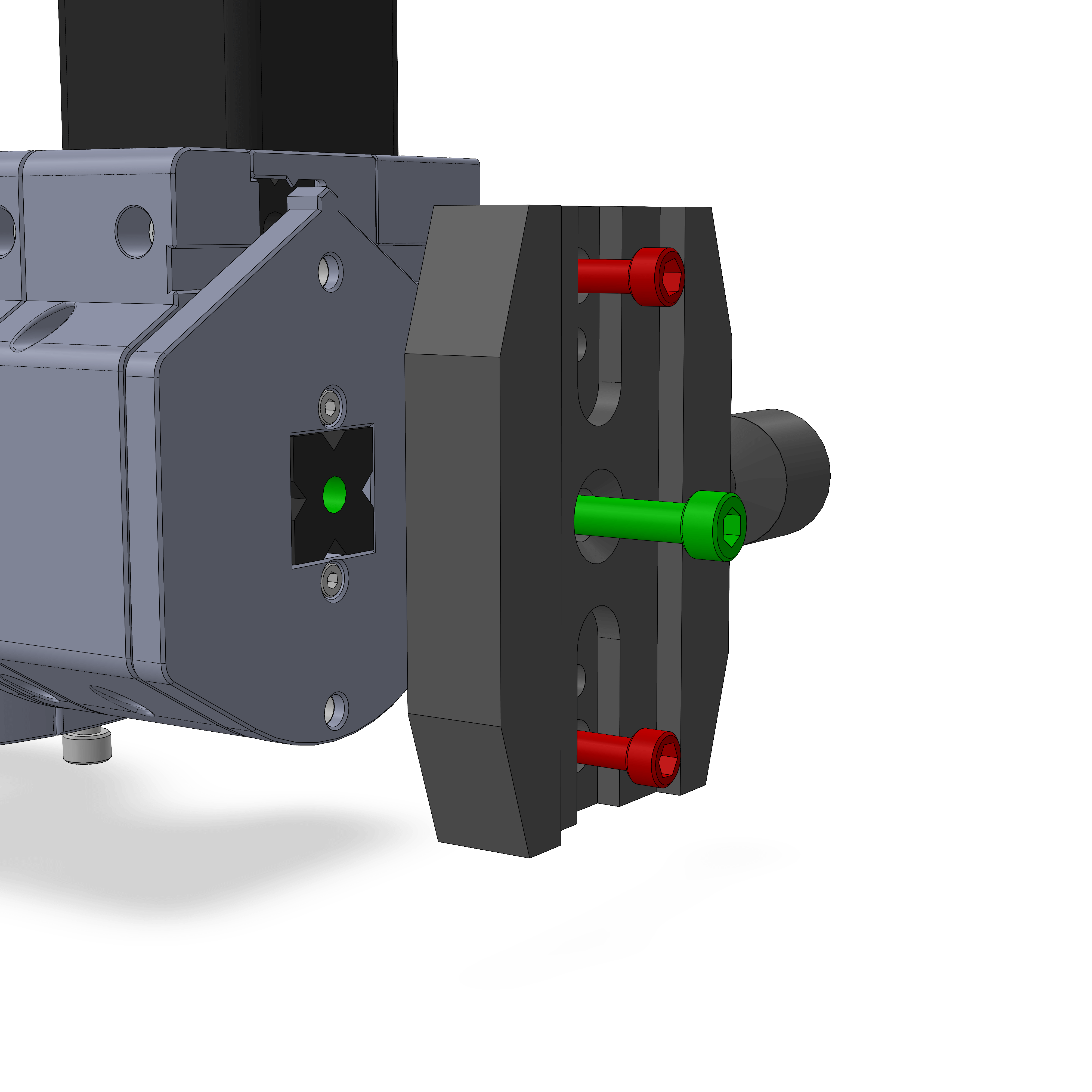
- Assembly
- Parts
- The two M5 screws (red) may look like they can hold weight because they're M5. Theses screws are only there to prevent the clamp from rotating. I would've used M3, but then they wouldn't have fit in the holes of the clamp. The part is not designed to hold your telescope by these screws. Attach them loosely for now.
- What holds your telescope is the center bolt (green). This will be either a M5x20 or M6x20, depending on the size of the center hole in your extrusions. This bolt is the only thing that holds your telescope, so make sure to tighten is good, but don't strip the threads.
- Then tighten the other two M5 bolts.
¶ Hardware
- 90N Camera Clamp
- 2x M5x12
- M5x20 or M6x20
¶ Step 34
- Assembly
- Parts
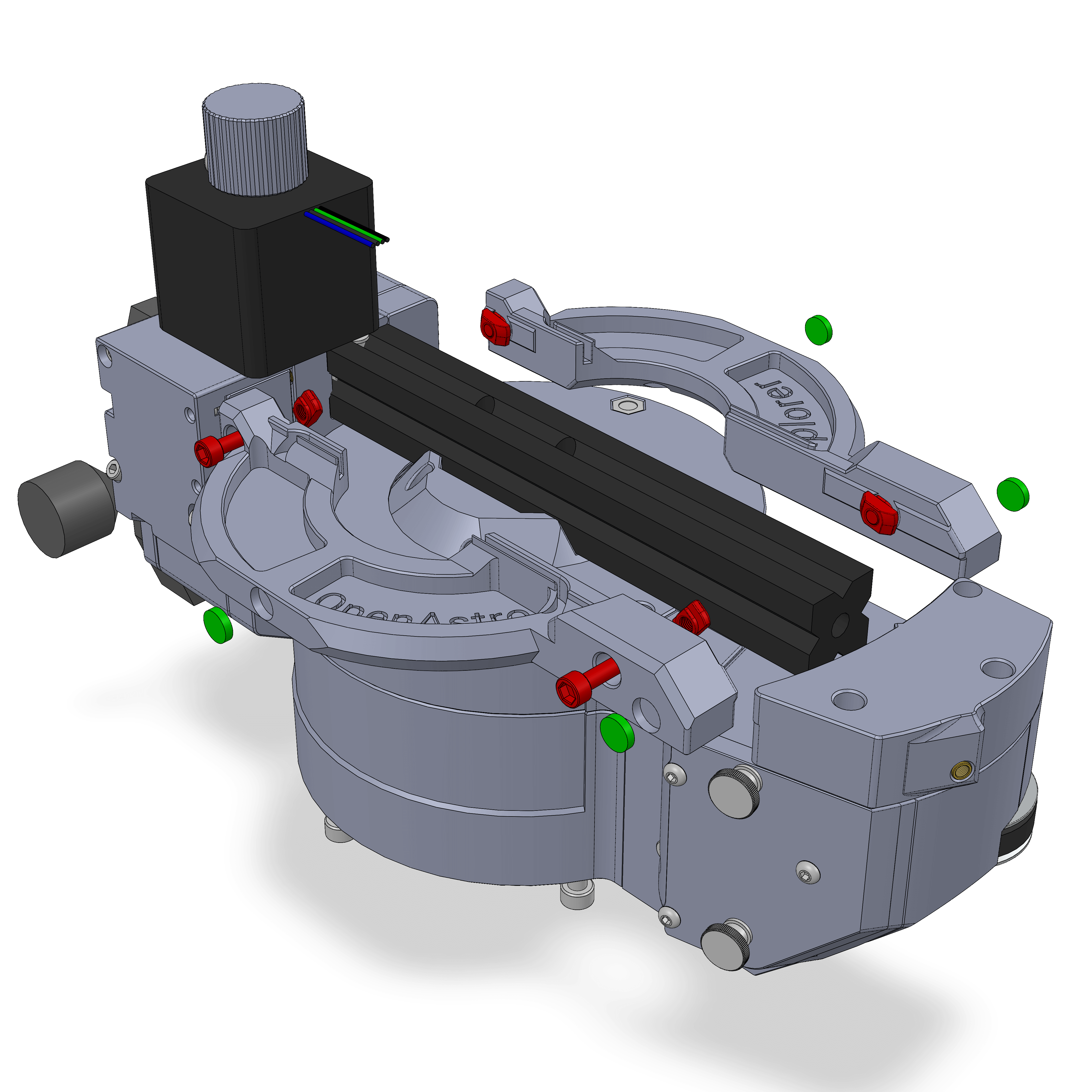
- Push the magnets (green) into the two parts as shown. They should sit a little bit past flush. If they tend to fall out, you can also give them a tiny drop of glue.
- Attach the parts with 2 M4x12 and TNuts each. The bottom of the parts should be aligned with the 2020 extrusion, there might be a small gap to the DEC assembly.
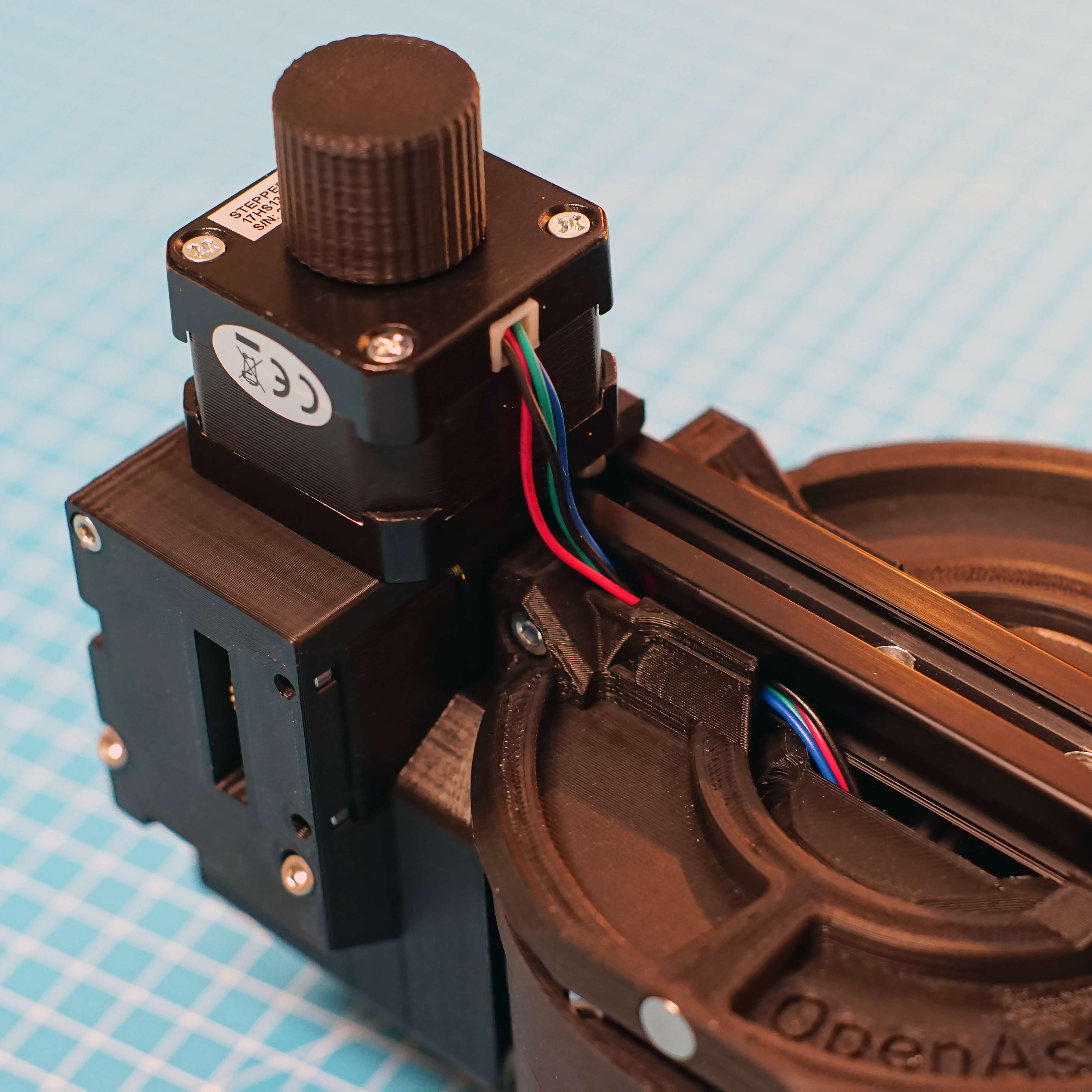
Route the DEC stepper wires as shown. Make sure they don't get pinched, you should be able to pull them in and out.

OAE Assembly Part 1: RA Gearbox
OAE Assembly Part 2: Base
OAE Assembly Part 3: DEC
OAE Assembly Part 4: AZ Base
OAE Assembly Part 5: ALT and Final Assembly
OAE Additional Assembly