¶ General
The firmware supports two boards based on the Raspberry Pi RP2040:
- BigTreeTech SKR Pico v1.0 - a compact controller with four on-board TMC2209 drivers (board ID
BOARD_RP2040_SKR_PICO) - JackW01 - a Raspberry Pi Pico on the pi-pico-printer-board carrier with four TMC2209 modules (board ID
BOARD_RP2040_JACKW01)
Both use the drivers in TMC2209 UART mode; A4988 or standalone driver types are not wired (the MS pins are not routed). All GPIO signals are 3.3 V logic.
The default pin assignments live in the firmware repository:
SKR Pico pins and
JackW01 pins.
An example configuration for the OAM is in the repo
¶ Features
¶ Supported
- RA/DEC motors, plus AZ/ALT (AutoPA) using the on-board TMC2209 drivers in UART mode (StealthChop)
- USB serial (Meade/LX200 protocol) - works with OATControl, the ASCOM driver and INDI without any handshake-line requirements
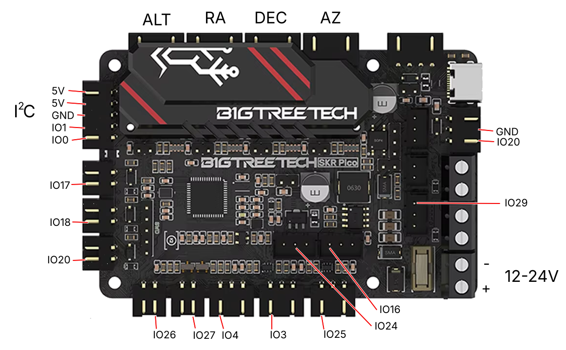
- GPS on the SKR Pico (default wiring on the left-side header), but only if no InfoDisplay
- Hall sensor homing on RA and DEC (RA Hall sensor)
- DEC endstop switches (SKR Pico)
- Info Display via I2C SSD1306 128x64 OLED, but then no GPS
- PWM fan output (SKR Pico FAN1)
¶ Not supported
- Arduino LCD menu shield (the configuration requires
DISPLAY_TYPE_NONE) - DigitalLevel gyro auto-leveling
- Focuser output (all four driver slots are used by the mount axes)
- WiFi (ESP32 boards only)
¶ Wiring
¶ Power (SKR Pico)
The board can be powered from USB (but withoput steppers), or from the VIN terminals (12-24 V), but not both - never leave the USB-power jumper fitted while VIN is applied. The jumper ties the 5 V rail to USB VBUS; with a supply also feeding the rail, the contention can hang the board during stepper driver initialization.
- Jumper removed + VIN (12-24 V) - normal operation. Motors and drivers are powered, and the USB connector still works for flashing and serial.
- USB only (jumper fitted) - the firmware boots and serial works, but the drivers have no motor power; nothing moves.
¶ Steppers
Drivers must be configured as DRIVER_TYPE_TMC2209_UART.
¶ SKR Pico (on-board TMC2209s)
| Axis | Slot | STEP | DIR | EN | DIAG / endstop input | TMC2209 UART address |
|---|---|---|---|---|---|---|
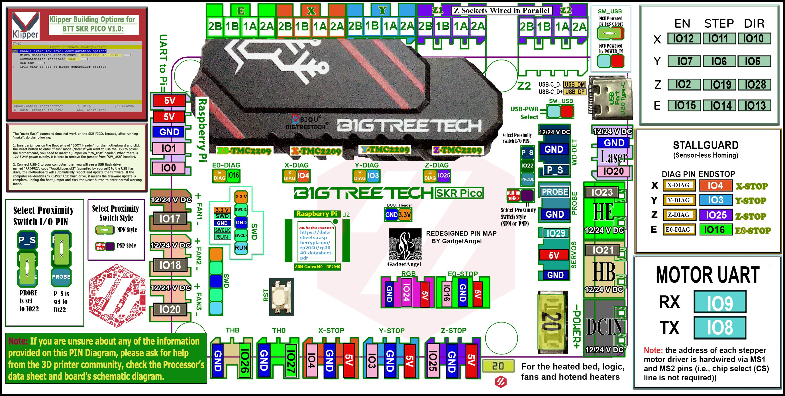
| RA | X | GP11 | GP10 | GP12 | GP4 | 0 |
| DEC | Y | GP6 | GP5 | GP7 | GP3 | 2 |
| AZ | Z | GP19 | GP28 | GP2 | - | 1 |
| ALT | E0 | GP14 | GP13 | GP15 | - | 3 |
Note the address order X=0, Y=2, Z=1, E0=3 - set by the MS1/MS2 strapping on the SKR Pico PCB and the opposite of the JackW01 board.
AZ and ALT are optional: set AZ_DRIVER_TYPE/ALT_DRIVER_TYPE to DRIVER_TYPE_NONE if your mount has no vertical axis motors.
¶ JackW01 (TMC2209 modules)
| Axis | Slot | STEP | DIR | EN | DIAG / endstop input | TMC2209 UART address |
|---|---|---|---|---|---|---|
| RA | X | GP7 | GP6 | GP5 | GP4 | 0 |
| DEC | Y | GP11 | GP10 | GP5 | GP3 | 1 |
| AZ | Z | GP13 | GP12 | GP5 | - | 2 |
| ALT | E | GP15 | GP14 | GP5 | - | 3 |
- EN is shared: all four enable lines are tied to GP5, so enable/disable always affects every axis. Per-axis current control happens over UART (IRUN/IHOLD) instead.
- Use BTT TMC2209 modules with the PDN_UART pad bridge (the on-board resistor linking RESET/TX and MS3/RX pads to PDN_UART). The carrier routes UART1 (GP8 TX, GP9 RX) to the driver sockets.
¶ USB serial
The USB port enumerates as a virtual COM port and carries the Meade/LX200 protocol. Hosts that open the port without asserting DTR (some C#-based tools) still receive replies. The board resets into BOOTSEL mode when a serial port opens at 1200 baud, or hold BOOTSEL while applying power.
Since these boards are quite quick, Baudrate is defualted to 115200 for them.
¶ Info Display
SSD1306 128x64 OLED on I2C. Configuration:
#define INFO_DISPLAY_TYPE        INFO_DISPLAY_TYPE_I2C_SSD1306_128x64
#define INFO_DISPLAY_I2C_ADDRESS 0x3C
#define INFO_DISPLAY_I2C_SDA_PIN 20
#define INFO_DISPLAY_I2C_SCL_PIN 21
The firmware's global defaults are SDA=5 / SCL=4. Those pins collide on the SKR Pico (GP5 is DEC direction, GP4 is the RA homing input), so always set the pins explicitly - GP0/GP1 are the recommended free pair, they are on a handy 5 pin port with 5V and GND. On the JackW01, pick any two free I2C-capable GPIOs.
¶ GPS (SKR Pico)
Wired to the left-side 5-pin header (IO0, IO1, GND, 5V) using UART0:
| GPS module pin | Connect to | RP2040 GPIO |
|---|---|---|
| RX (module input) | IO0 | GP0 (MCU TX) |
| TX (module output) | IO1 | GP1 (MCU RX) |
| VCC | 5V | - |
| GND | GND | - |
Enable with #define USE_GPS 1. Any GPS module with a 3.3 V UART output works (the RP2040 GPIO are not 5 V tolerant). The JackW01 board has no default GPS wiring; leave USE_GPS at 0.
¶ Hall homing sensors
Active-LOW inputs on the endstop headers:
| Axis | Input | GPIO |
|---|---|---|
| RA | X-STOP | GP4 |
| DEC | Y-STOP | GP3 |
The inputs are configured without pull-ups; open-drain Hall sensors need an external pull-up (10 kΩ to 3.3 V). Search distance and active state are configurable (RA_HOMING_SENSOR_PIN, RA_HOMING_SENSOR_ACTIVE_STATE, ..._SEARCH_DEGREES).
¶ DEC endstops (SKR Pico)
The two remaining endstop inputs can back up Hall homing with hardware limits, both active LOW:
| Limit | Input | GPIO | Config key |
|---|---|---|---|
| DEC down | Z-STOP | GP25 | DEC_ENDSWITCH_DOWN_SENSOR_PIN |
| DEC up | E-STOP | GP16 | DEC_ENDSWITCH_UP_SENSOR_PIN |
RA endstops have no default wiring on these boards - all four endstop inputs are allocated above.
¶ Fan (SKR Pico)
The FAN1 header is switched by a MOSFET on GP17 and carries the VIN rail. Set the power percentage with RP2040_FAN1_POWER_PERCENT (0-100, default 100) in your configuration.
¶ SKR Pico Pinout