¶ Info Displays
As of V1.13.3, the firmware supports the concept of informational (read-only) displays (that have no input) on ESP32 and MKS systems. Currently only one such display is supported:
- SSD1306-based I2C 128x64 pixel OLED displays (from AliExpress or Amazon)
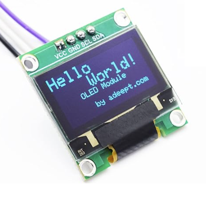
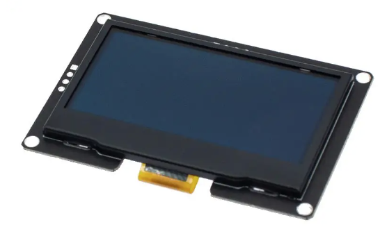
These are two examples of 128x64 OLED screens. The left one is 1" and the right on 2.4" in size.
If using an MKS board, you will not be able to use the E1 stepper socket (usually used for focuser), since the I2C pin on the MKS is used for UART communications with that stepper controller.
Adding another display would be pretty easy, the firmware has abstracted it reasonably well...
¶ Firmware Configuration for MKS (typically used for OAT or OAM)
To enable the info display, add the following lines to your local config file:
#define INFO_DISPLAY_TYPE         INFO_DISPLAY_TYPE_I2C_SSD1306_128x64
#define INFO_DISPLAY_I2C_ADDRESS  0x3C
#define INFO_DISPLAY_I2C_SDA_PIN  20
#define INFO_DISPLAY_I2C_SCL_PIN  21
¶ Firmware Configuration for ESP32 (typically used for OAE)
To enable the info display, add the following lines to your local config file:
#define INFO_DISPLAY_TYPE         INFO_DISPLAY_TYPE_I2C_SSD1306_128x64
#define INFO_DISPLAY_I2C_ADDRESS  0x3C
#define INFO_DISPLAY_I2C_SDA_PIN  21
#define INFO_DISPLAY_I2C_SCL_PIN  22
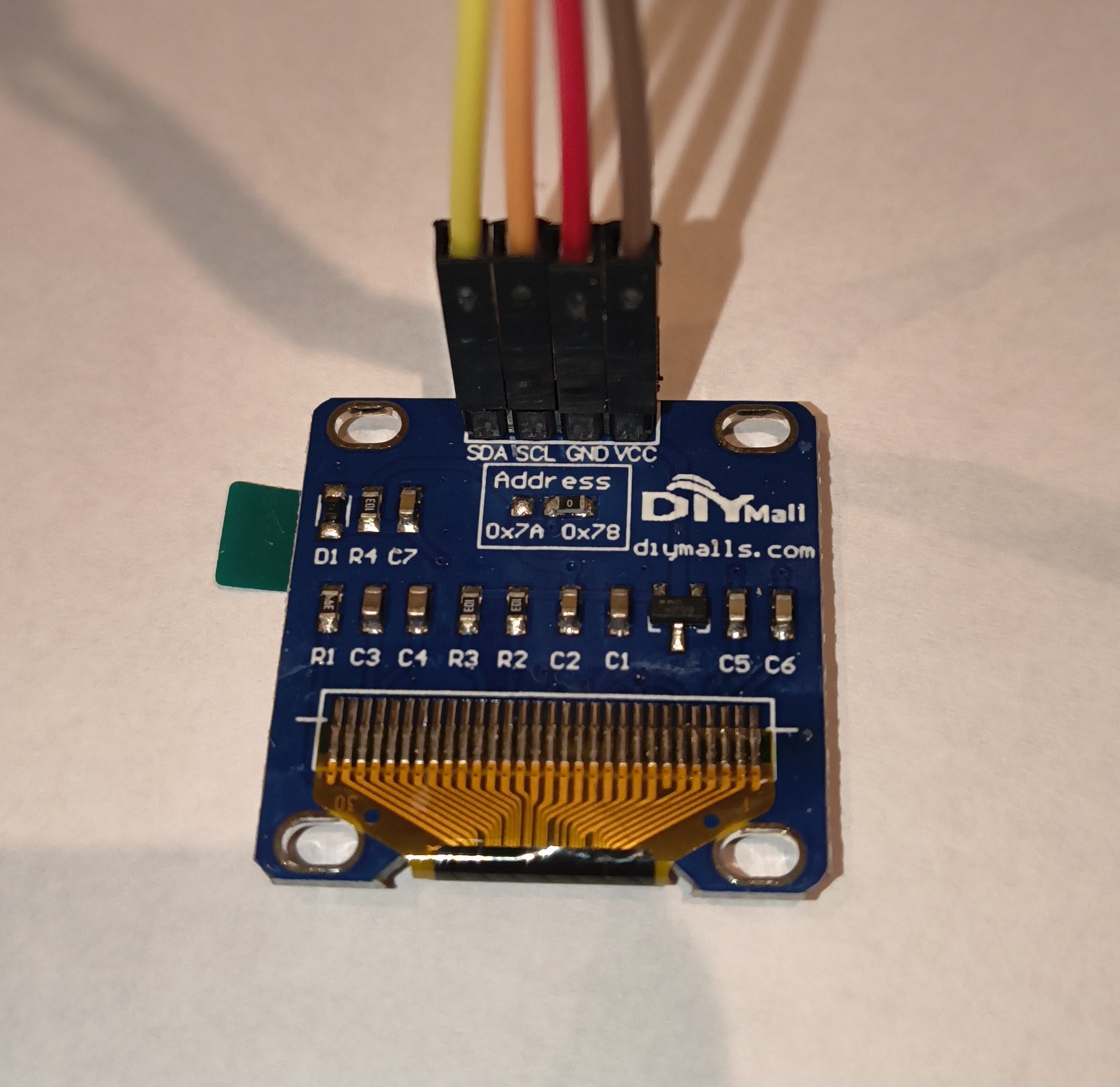
This should work for the ESP32 on the OAE board although you may need to change the I2C address as that can differ from the default of 0x3C depending upon the manufacturer of the OLED display. The default address should work for most boards of this type but some are known to use other addresses, such as 0x78 and 0x7A, it usually indicates if this is the case in the board documentation or on the text printed on the circuit board.
¶ Wiring
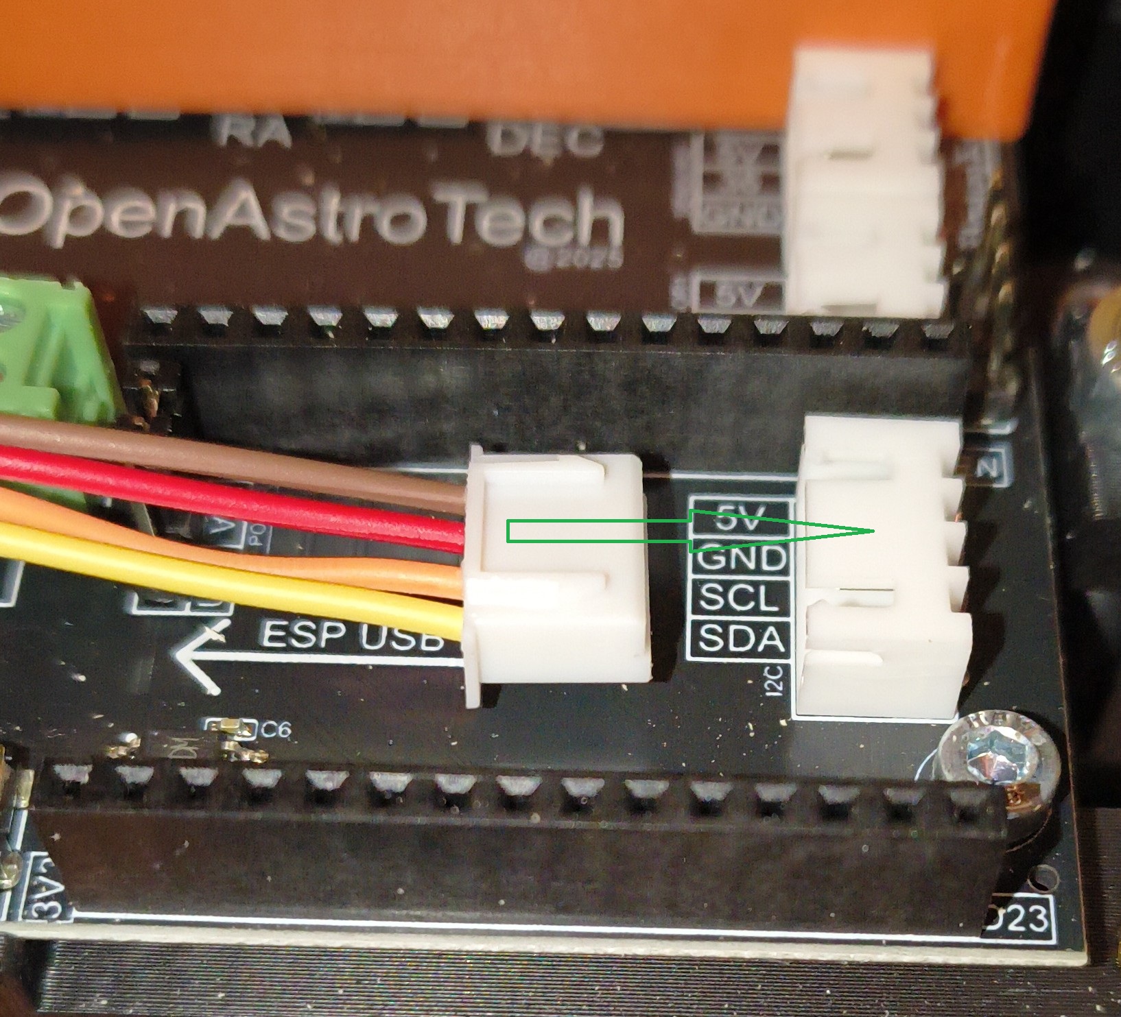
I2C devices just need 4 wires connected, 3.3V (sometimes 5V, see below), Gnd, Clock (SCL) and Data (SDA).
Note that the OLED displays linked above require 3.3V so a step-down buck converted is needed for the MKS, since 3.3V is not available on that board. I believe the ATMega2560 has a 3.3V pin, as does the ESP32.
You can often power these OLED displays with 5V and the board's circuitry (regulator/level shifter) handles the 3.3V logic levels (as shown in many Arduino tutorials). So some OLED modules can be powered direct from the 5V of the I2C socket on the OAE board, but do check the specification of the OLED display you have purchased as you may damage the display module if it does not support a 5V input.
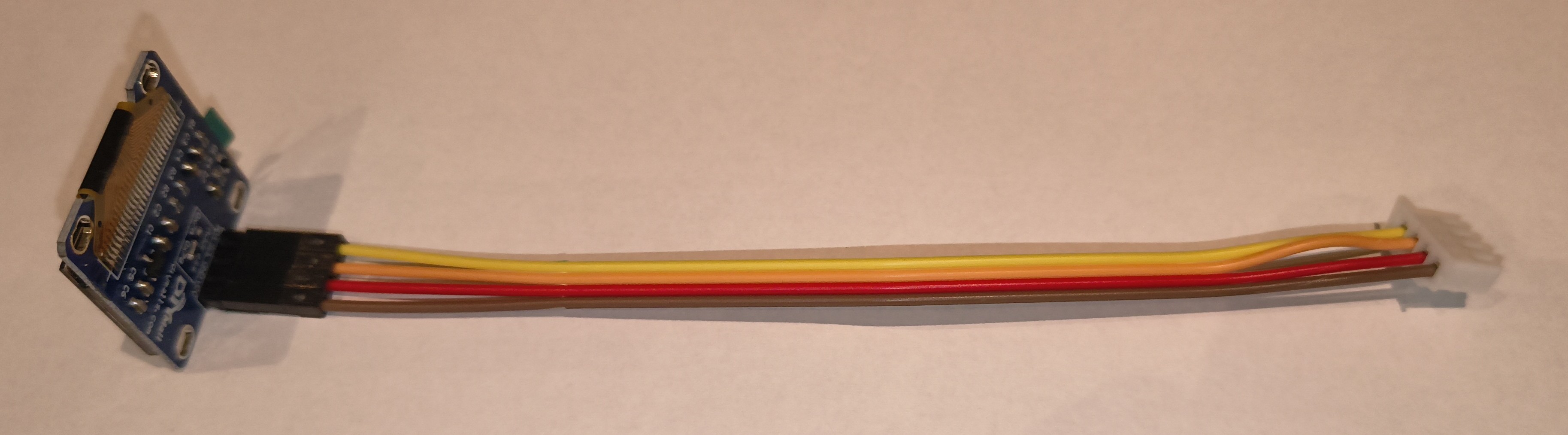
Here's an example of the straight-through wiring from the I2C interface socket on the OAE ESP32 board (the white JST connector) to the pinout on the SSD1306 board (the black dupont connector).
¶ Displayed Information
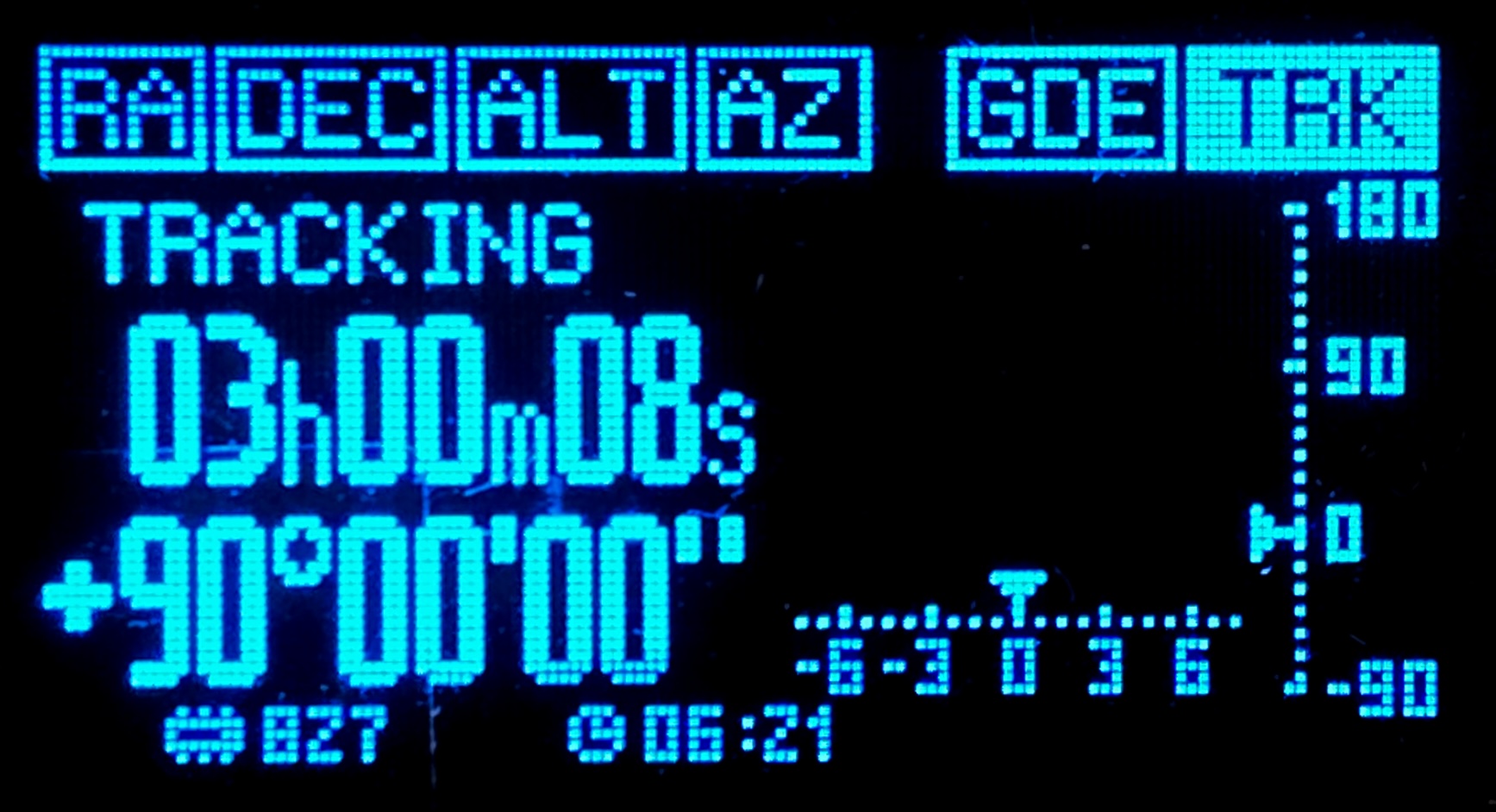
The display will show:
- Boot activity/progress
- Stepper activity per stepper
- Mount status
- RA and DEC coordinates
- Communication status
- Alive indicator
- Available memory
- Safe time remaining, Location, LST and Uptime
- Slew operations will also display a progress bar.