¶ General
The MKS Gen L V2.1 or V2.0 is the recommended main board for the OAT. Make sure that at the V2.1 board a jumper is set at "Drive IC Power 5V".
The MKS Gen L v1.0 can work if the newer versions are not readily available, however some additional wiring is required for UART driver control. This board is functionally equivilent to the RAMPS.
¶ Features
¶ Supported
- RA/DEC Motors using NEMA or bi-polar modified 28BYJ steppers
- UART support (additional wiring required)
- AutoPA support using NEMA or bi-polar modified 28BYJ steppers
- Arduino LCD shield with buttons
- GPS
The whole point of the MKS is to reduce wiring and using 28BYJ steppers requires relatively complex wiring of an external ULN2003.
¶ Partial Support:
- DigitalLevel - Supported on MKS L V2.1 boards.
¶ Firmware
Generate your configuration using the OAT Firmware Configurator and choose the correct board.
¶ Wiring
¶ Motor Wiring
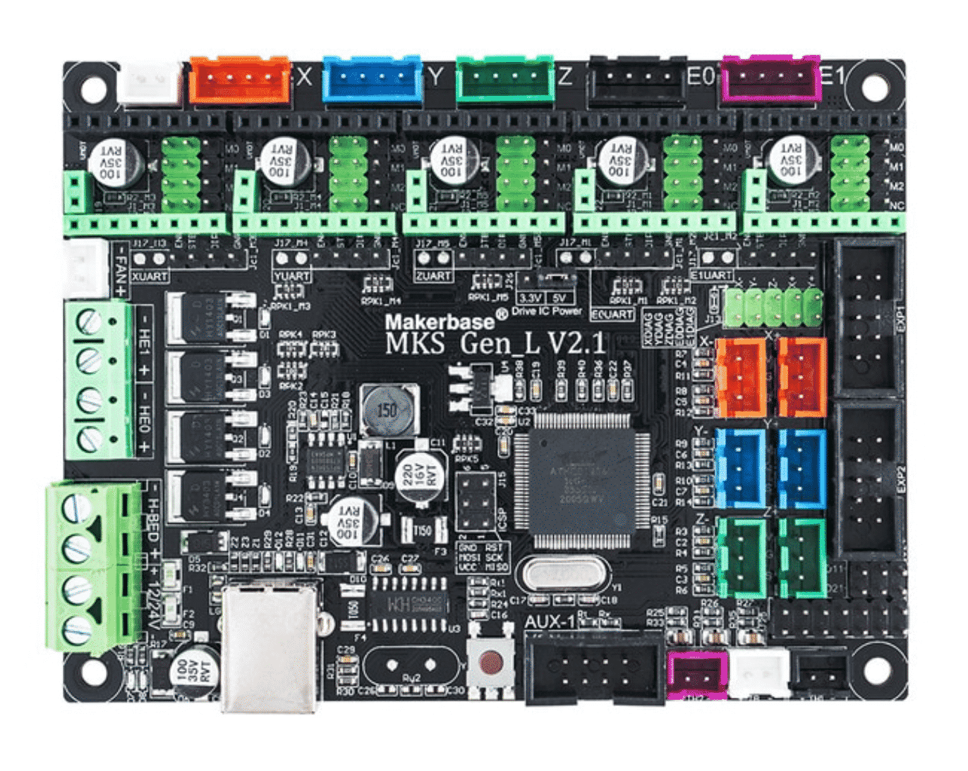
The default wiring has the steppers for RA, DEC, AZ, ALT and Focuser connected to the X, Y, Z, E0 and E1 plugs:
RA:   X (red)
DEC:  Y (blue)
AZ:  Z (green)
ALT:   E0 (black)
FCS:  E1 (purple)
¶ UART Wiring
UART describes a communication between the MCU and driver. Instructions like current settings, microstepping and others can be sent directly to the driver.
Every TMC2209 and 2208 supports this, however with some manufacturers you have to manually enable it by soldering a small bridge.
BTT TMCs always have this enabled, but if you use any other brands and have issues getting UART to work see the UART wiring page
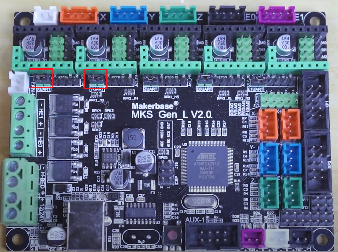
For V2.1 and V2.0 boards, all UART wiring is internal to the board and no additional wiring is necessary. To enable UART, jumpers need to be inserted for each driver connected.
For V1.0, minor wiring/changes are required.
¶ MKS Gen L V2.1
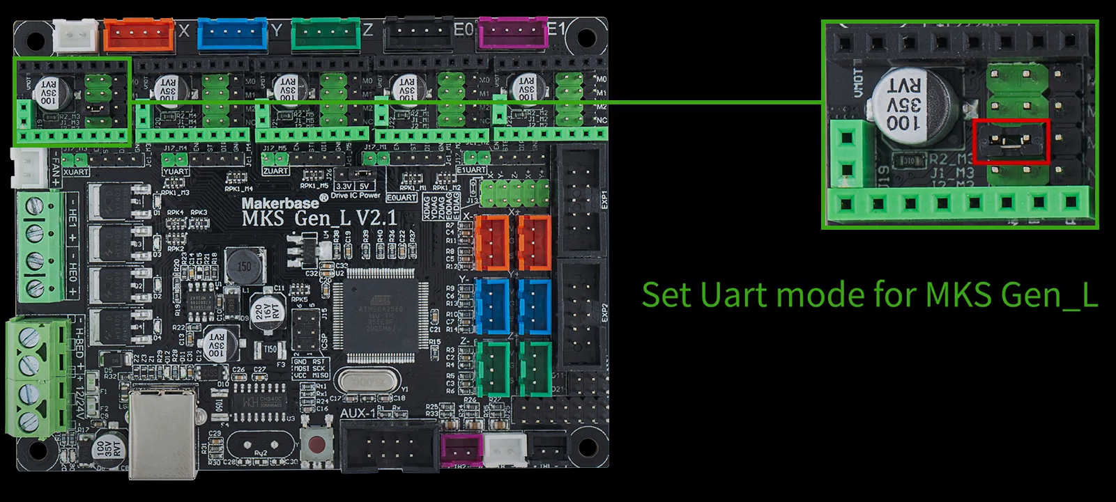
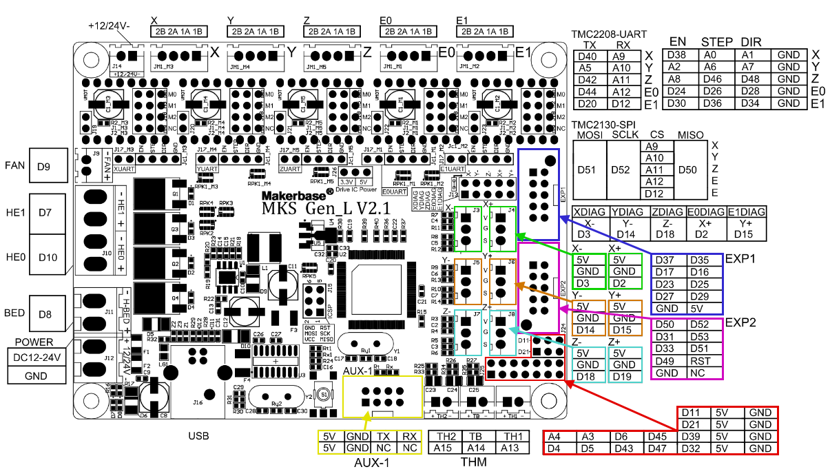
The pinout diagram looks as follows:
¶ MKS Gen L V2.0
If your V2.0 came with jumpers installed, remove all of them.
¶ MKS Gen L V1.0
If using UART on this board, it is very similar to wiring UART on a RAMPS board with two minor changes:
-
Both of the downward facing UART pins of the TMC2209 (or TMC2208) driver needs to be bent outwards (or cut off) to prevent them being inserted into the driver header. See here for reference. UART will not work properly otherwise.
-
The pins to connect to on the MKS are as follows:
| Motor | TX | RX | ||
|---|---|---|---|---|
| RA | RA_SERIAL_PORT_TX | D4 | RA_SERIAL_PORT_RX | D49 |
| DEC | DEC_SERIAL_PORT_TX | D5 | DEC_SERIAL_PORT_RX | D50 |
| Az | AZ_SERIAL_PORT_TX | D6 | AZ_SERIAL_PORT_RX | D51 |
| Alt | ALT_SERIAL_PORT_TX | D11 | ALT_SERIAL_PORT_RX | D52 |
| Focuser | Not supported |
The pinout of the MKS Gen L v1.0 can be found here.
Refer to the RAMPS wiki page for additional details.
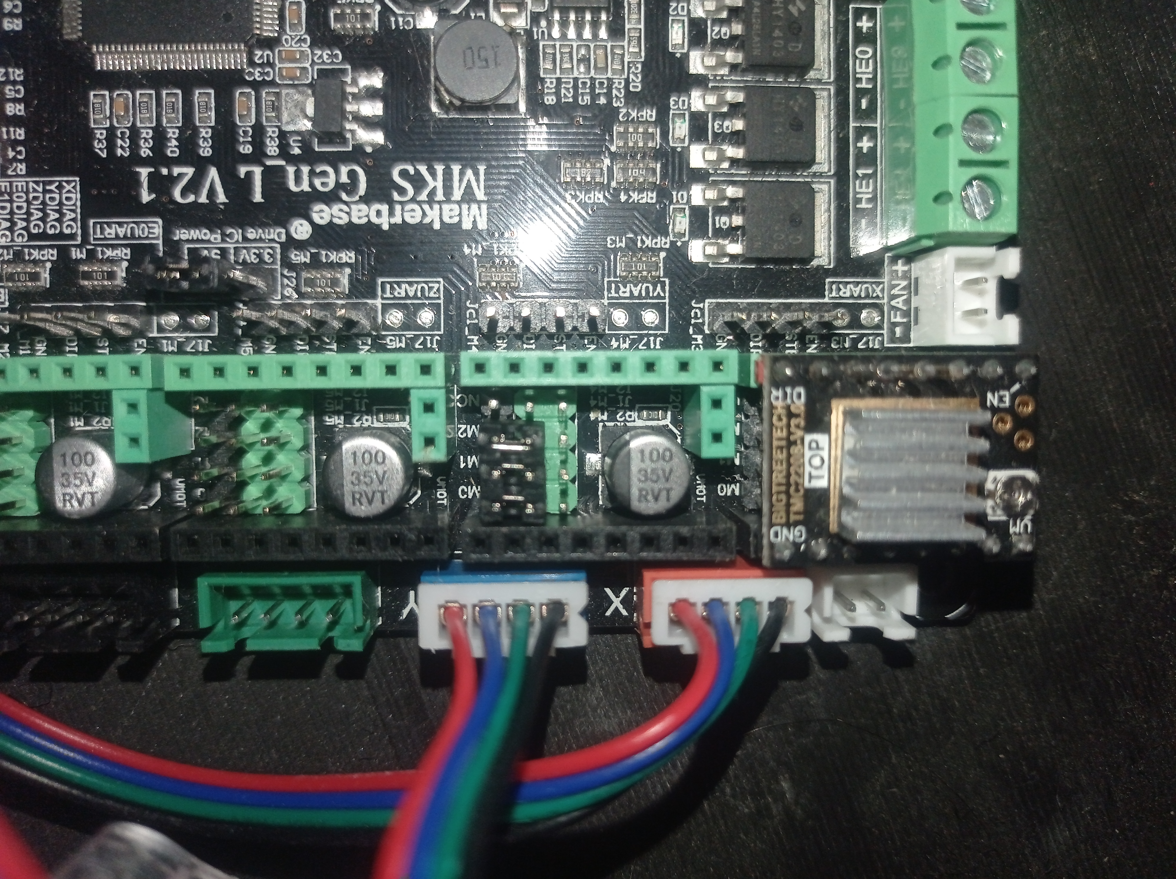
¶ Wiring A4988 Drivers for MKS gen l 2.1
You need to use three jumpers to enable 1/16 microstepping.
¶ Display (Optional)
For how to wire the LCD, see here.
¶ Capacitor (Optional)
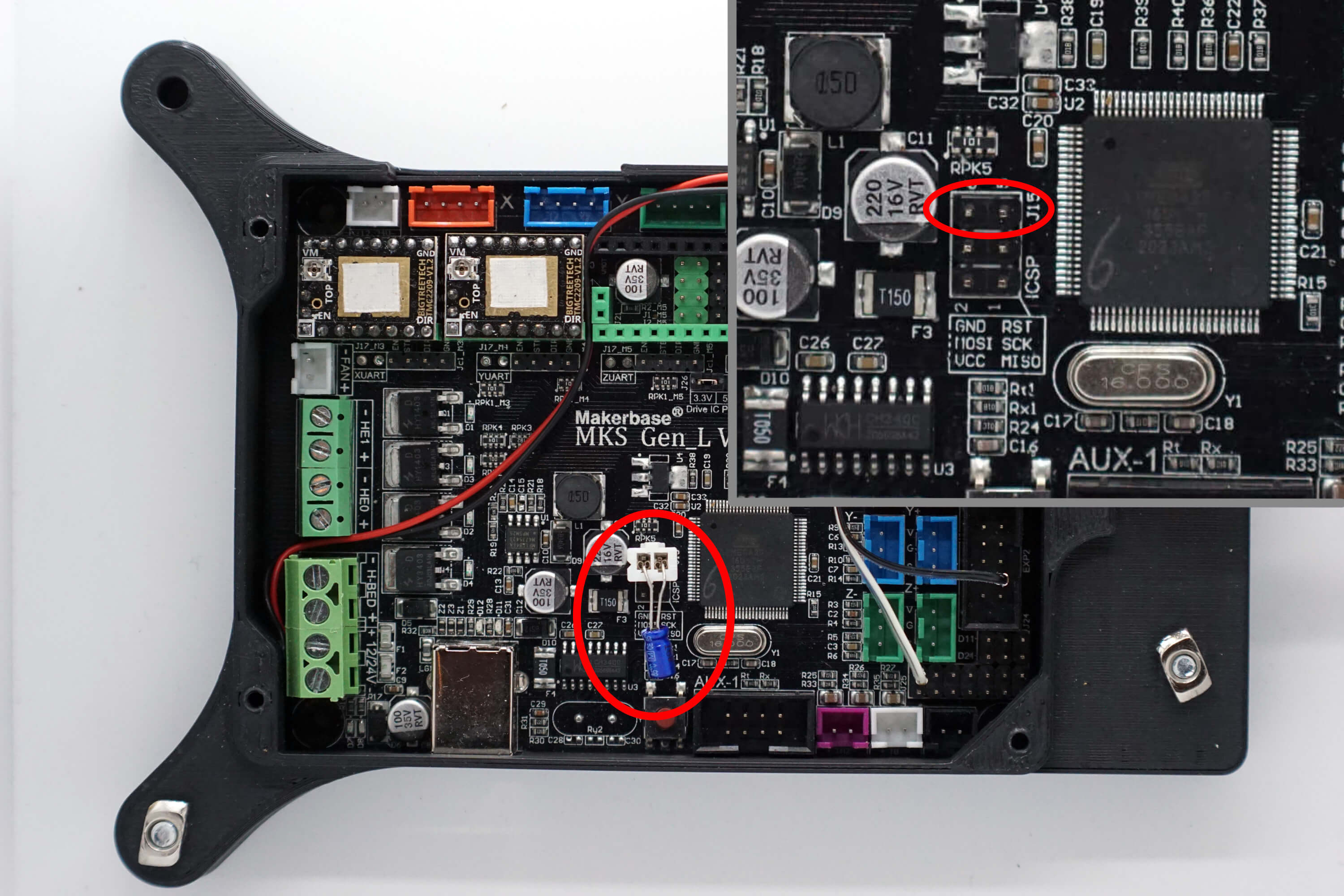
Adding a capacitor (between 10 and 25uF) to the RST/GND pins will solve an inconvenience where the board resets on the first attempt at connection to OAT via OATControl. This step is optional but will make connecting to the OAT quicker. Please note that when flashing firmware, the capacitor must be removed.
- Find a way to attach the capacitor to the MKS. A nice way is to crimp a JST-XH connector to it.

Place the capacitor at the shown location, with the negative terminal of the capacitor on the left hand pin in the image - See the MKS Gen L v1.0 pinout here. Negative goes to GND and positive to RST.
¶ Pin Reference MKS Boards
MKS Gen L 2.1: https://github.com/makerbase-mks/MKS-GEN_L/blob/master/hardware/MKS Gen_L V2.1_001/MKS GEN_L V2.1_001 SCH.pdf
MKS Gen L 2.0: https://github.com/makerbase-mks/MKS-GEN_L/blob/master/hardware/MKS Gen_L V2.0_001/MKS Gen_L V2.0_001 SCH.pdf
MKS Gen L 1.0: https://github.com/makerbase-mks/MKS-GEN_L/blob/master/hardware/MKS Gen_L V1.0_008/MKS Gen_L V1.0_008 SCH.pdf
¶ Troubleshooting
¶ USB not recognized
If you have trouble connecting to the MKS board your probably missing the CH340 driver. Download from here: https://sparks.gogo.co.nz/ch340.html
¶ UART not working
If your are not using BTT drivers, you might have to manually enable UART