¶ LCD Case and Wiring
¶ Where to get the Parts
The LCD case is available for download from the GitHub OpenAstroTracker Addons repo.
Note: If you access and STL and it opens in your browser as some text file with a bunch of numbers, use the File > Save As command to save the STL.
¶ Required Hardware
- LCD shield
- 10-pin ribbon cable
- 10-pin M-F Dupont cables
- 2x 10-pin IDC connector
- 2x JST or Dupont crimp, female
- Crimp tool
Optionals
- 8x M3x4.6x6mm Heatserts
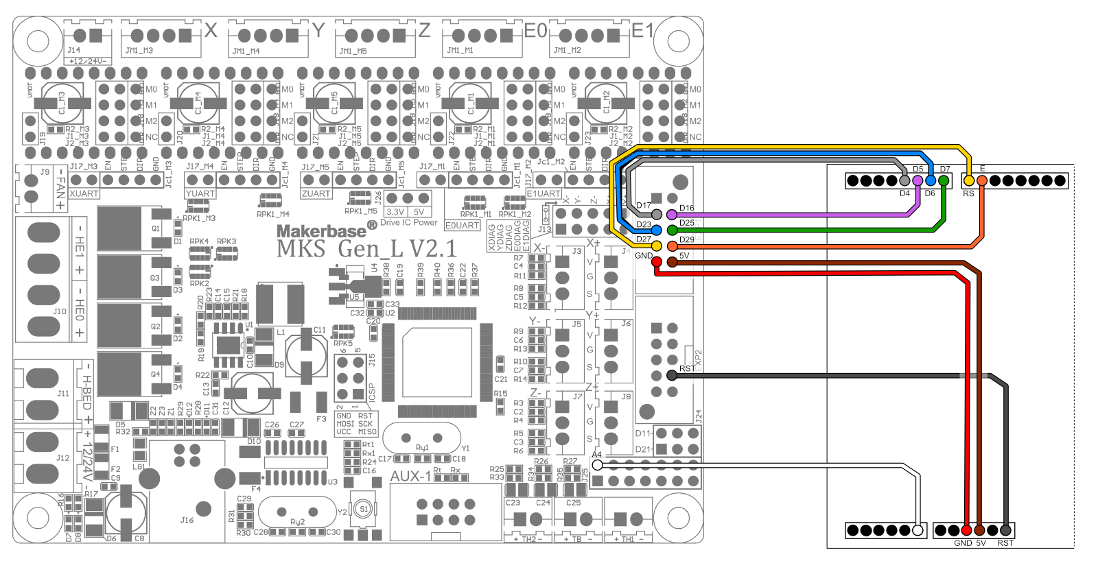
¶ MKS Gen_L V2.1 Wiring Diagram
¶ Ribbon Cable and LCD-side Termination
For simplicity's sake, it's highly recommended to use color coded cables to be able to follow the guide.
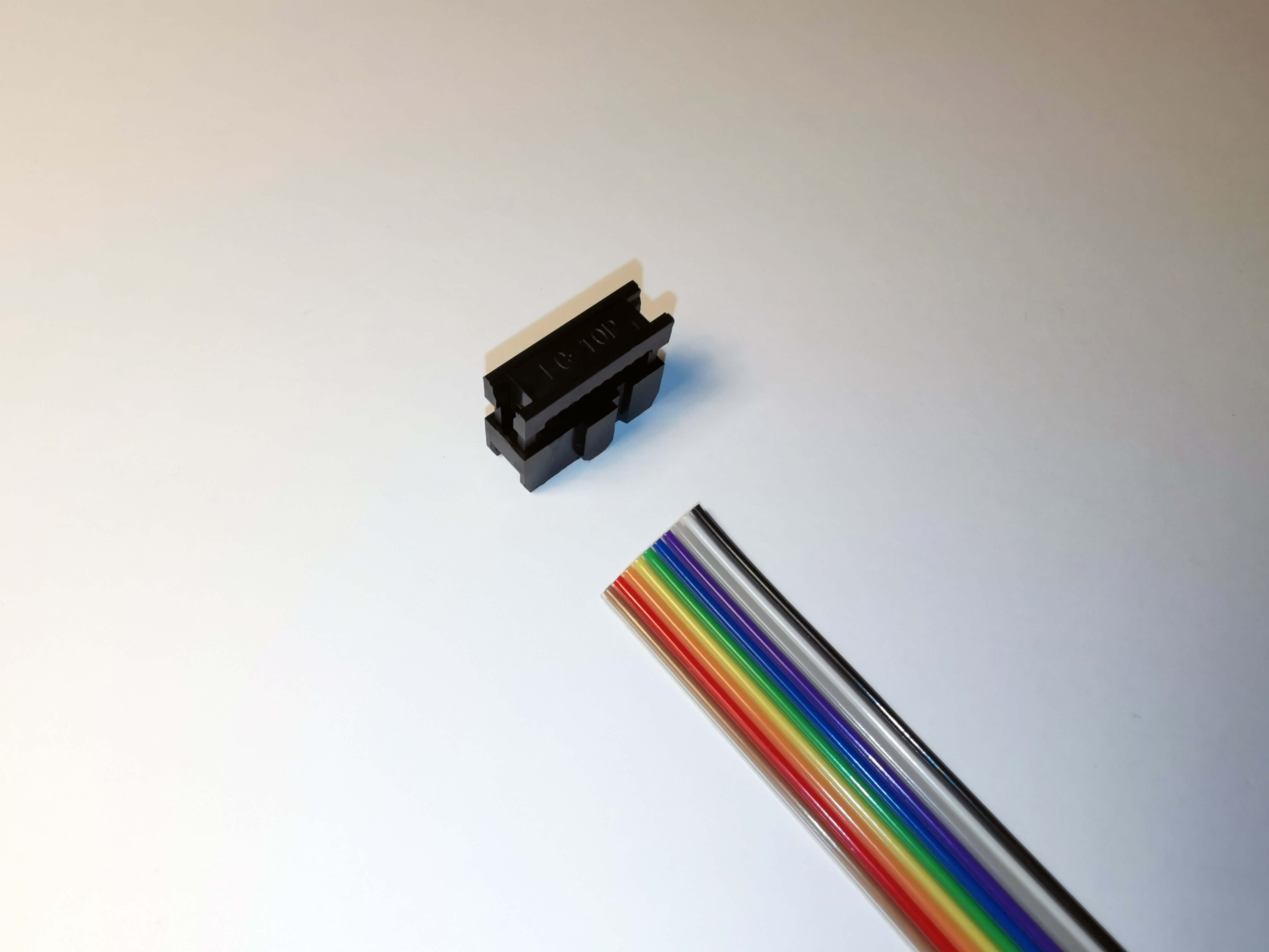
Cut about 50cm (or more if you like) of the 10 pin ribbon cable. Insert one end into the IDC connector in exactly the way its shown in the following image. The black cable on the right side and the little notch on the connector facing the cable.
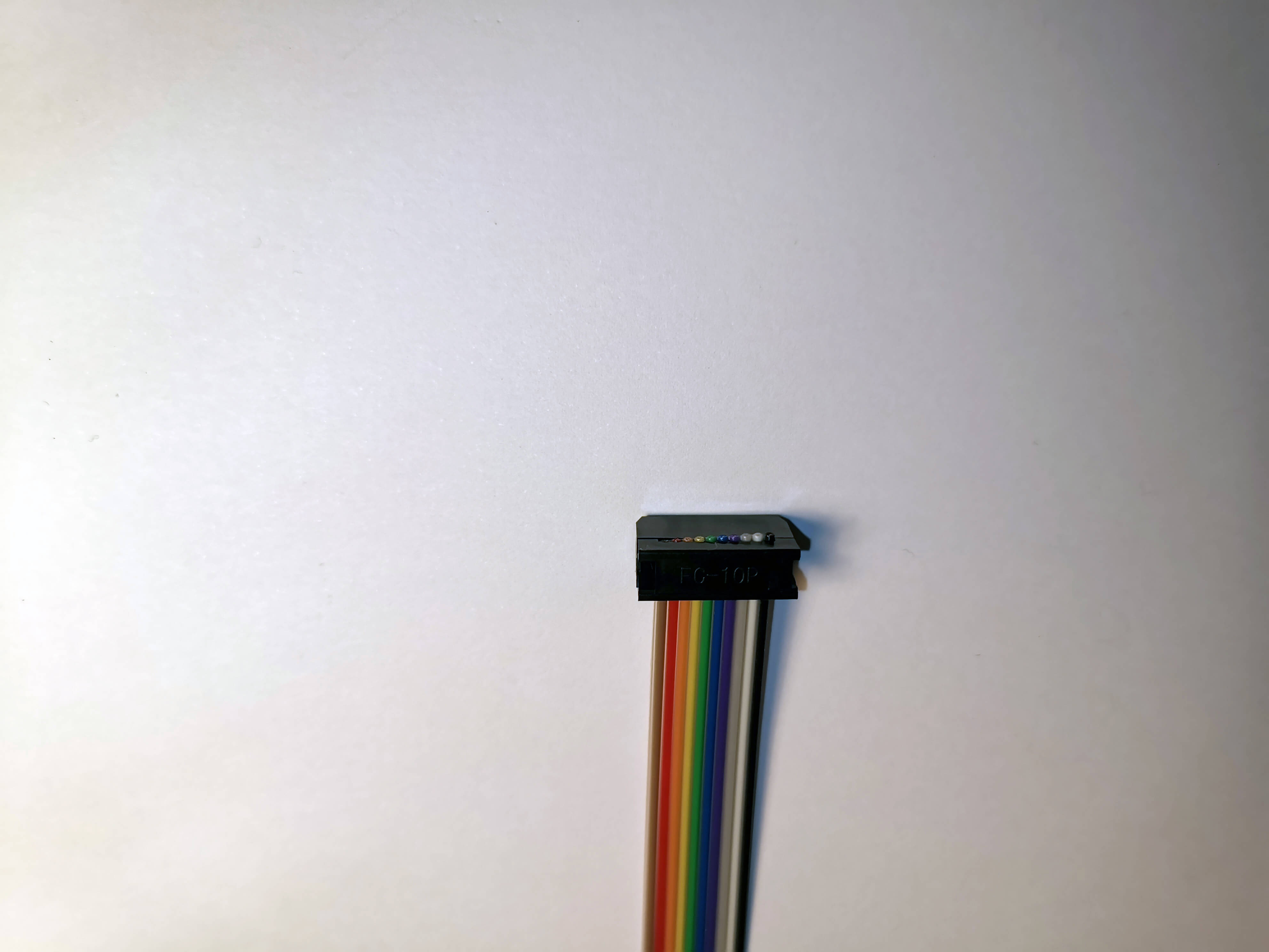
Close the connector. There's a special tool for that but you can do it with force. I recommend doing it with two flat and sturdy pieces of wood or something similar.
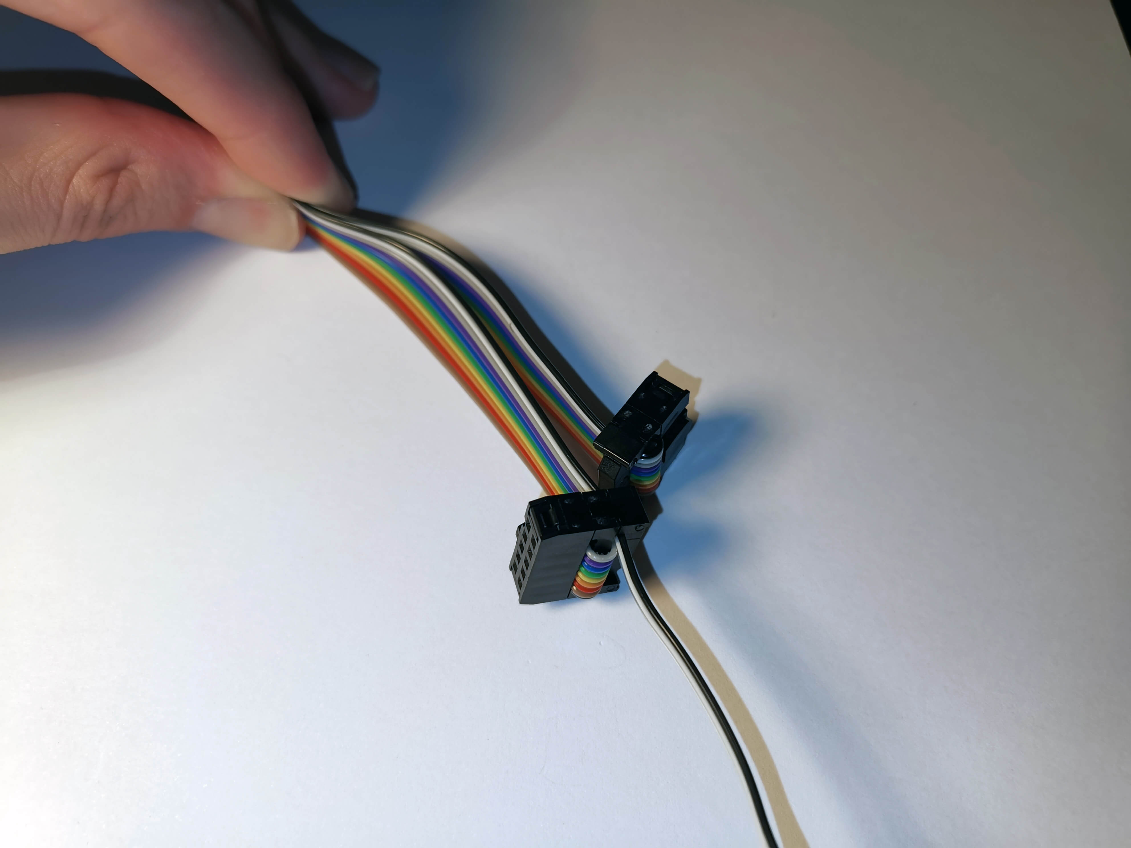
Bend the ribbon cable around and attach the strain protectors.

Get 10 M-F Dupont cables. Again, highly recommend to use color coded ones.
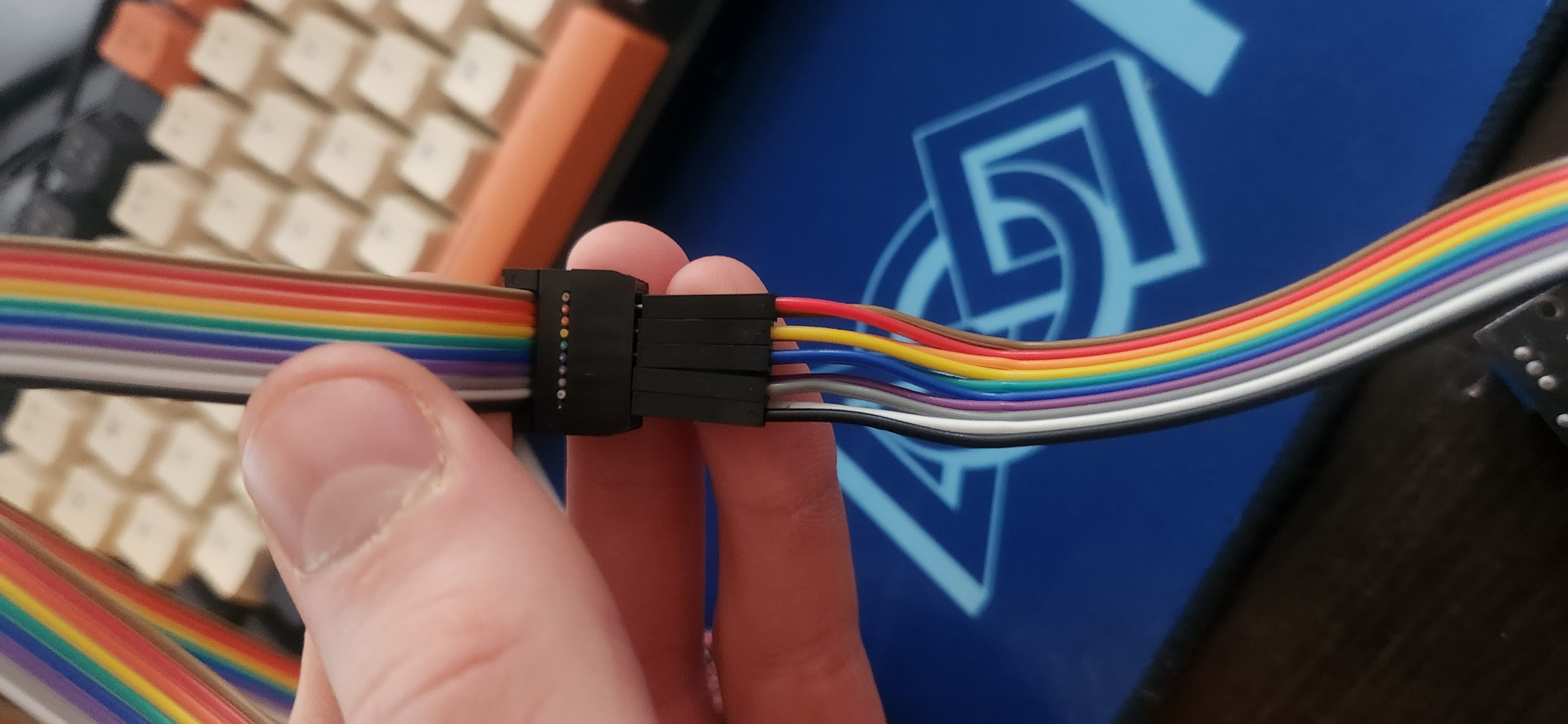
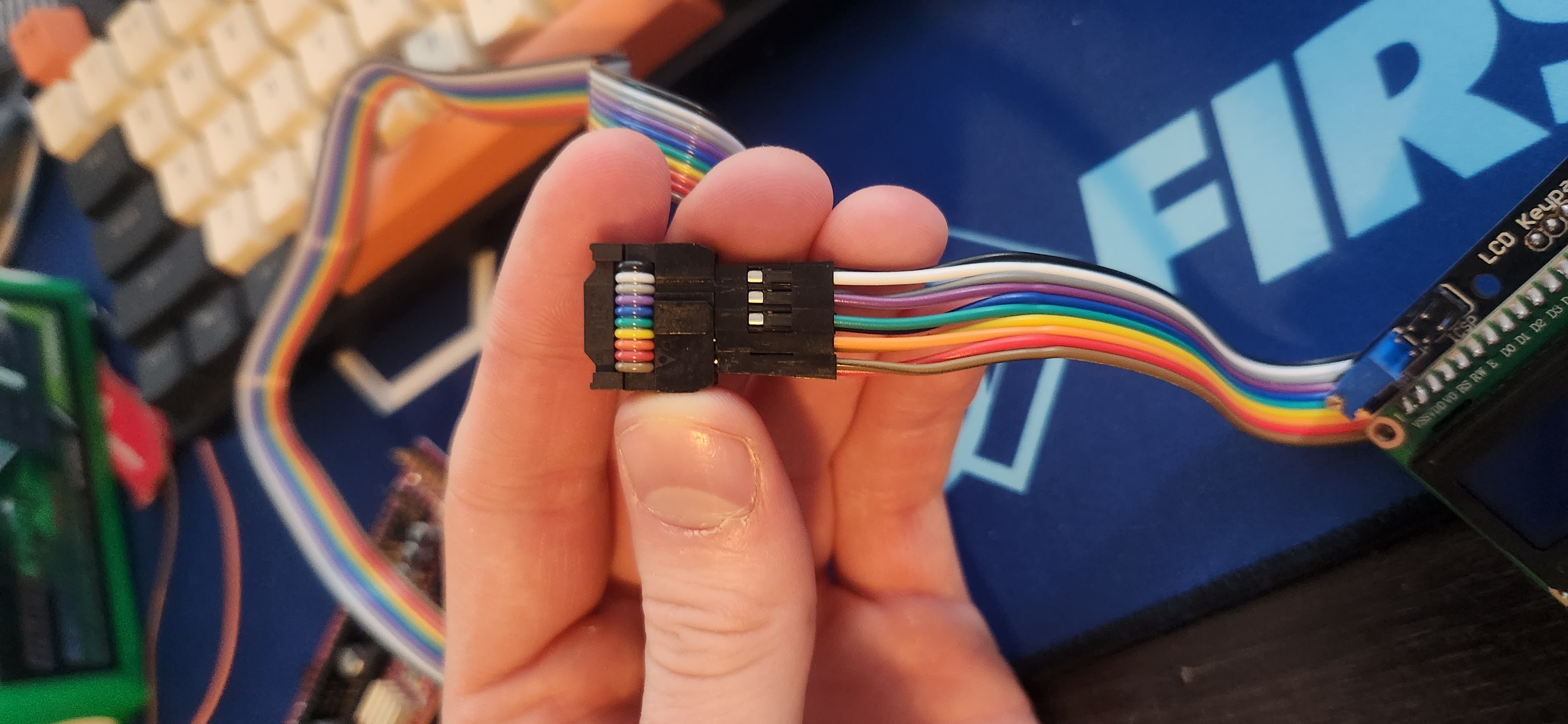
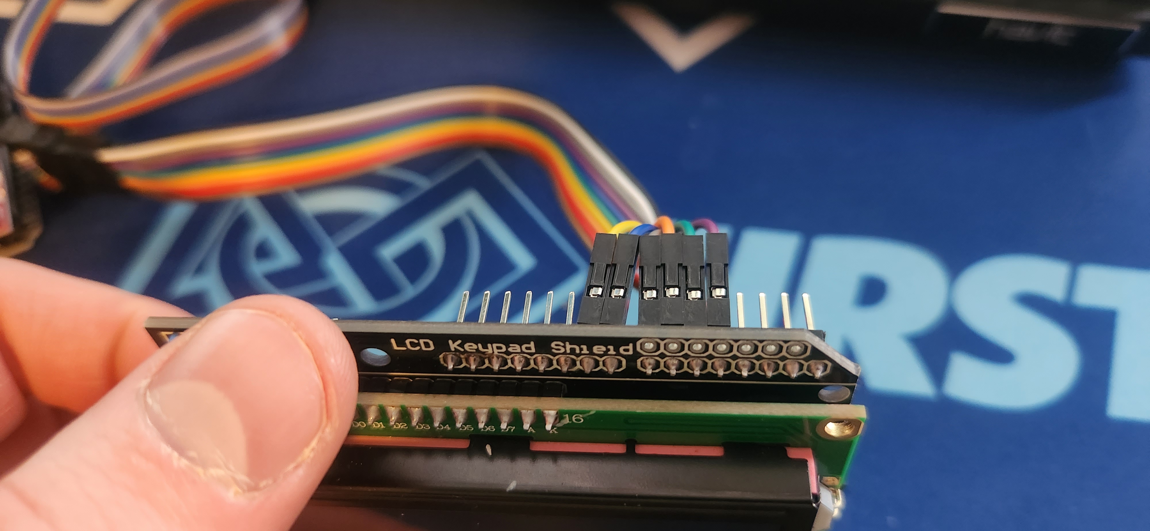
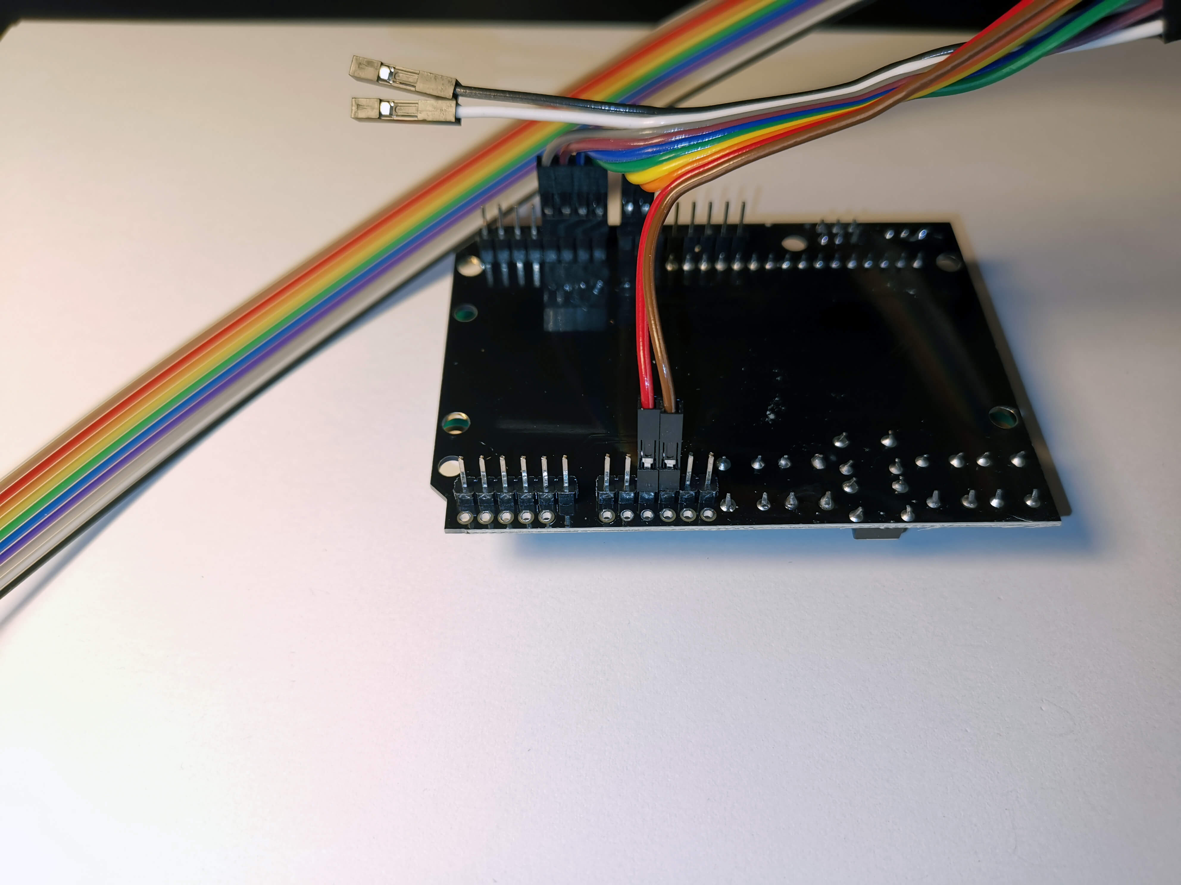
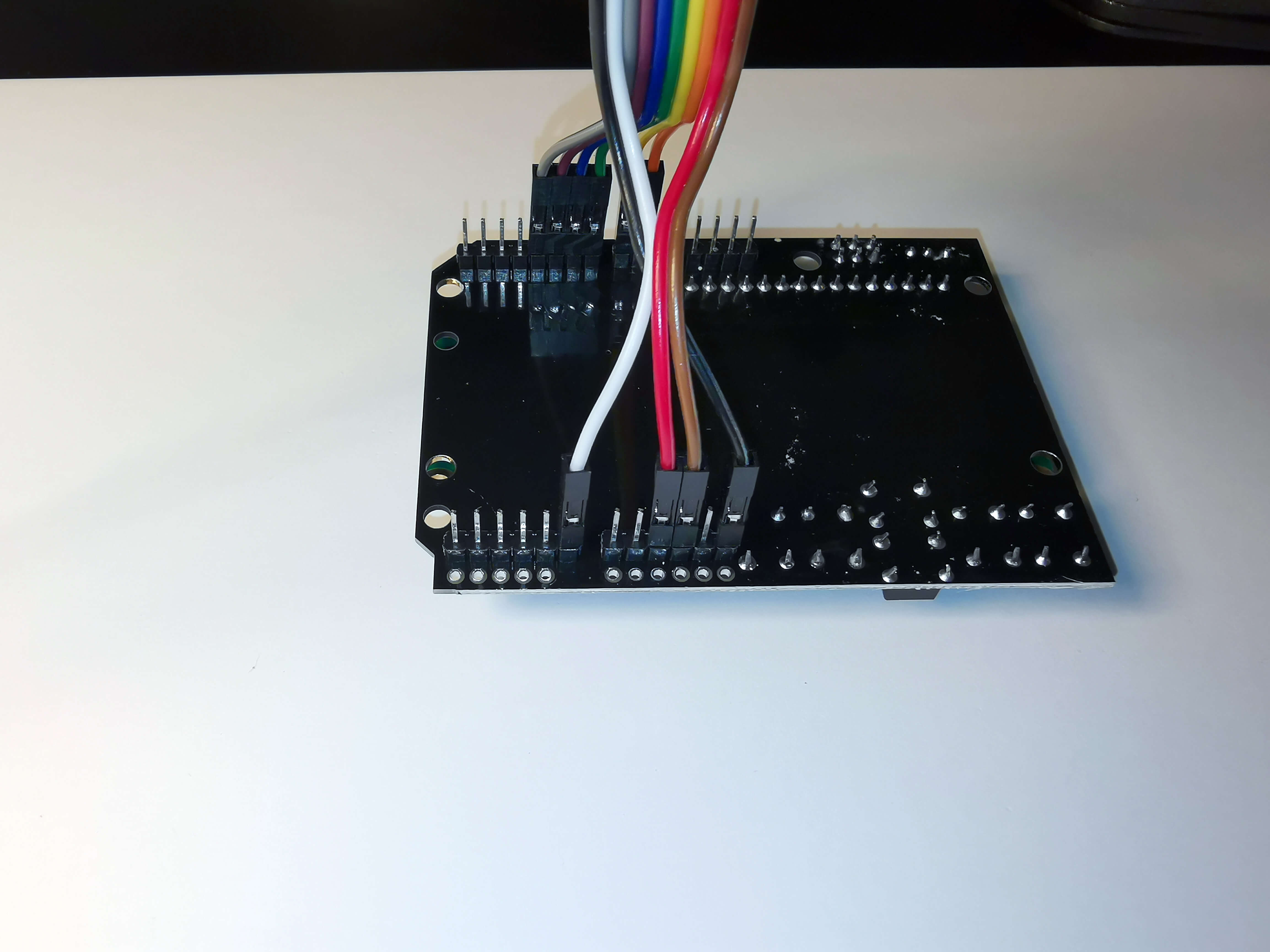
Hold the LCD side of the ribbon cable (the one without the black and white cable sticking out) as shown. Insert the Black and White cable to the Duponts in exactly the shown way, in the bottom two connectors.
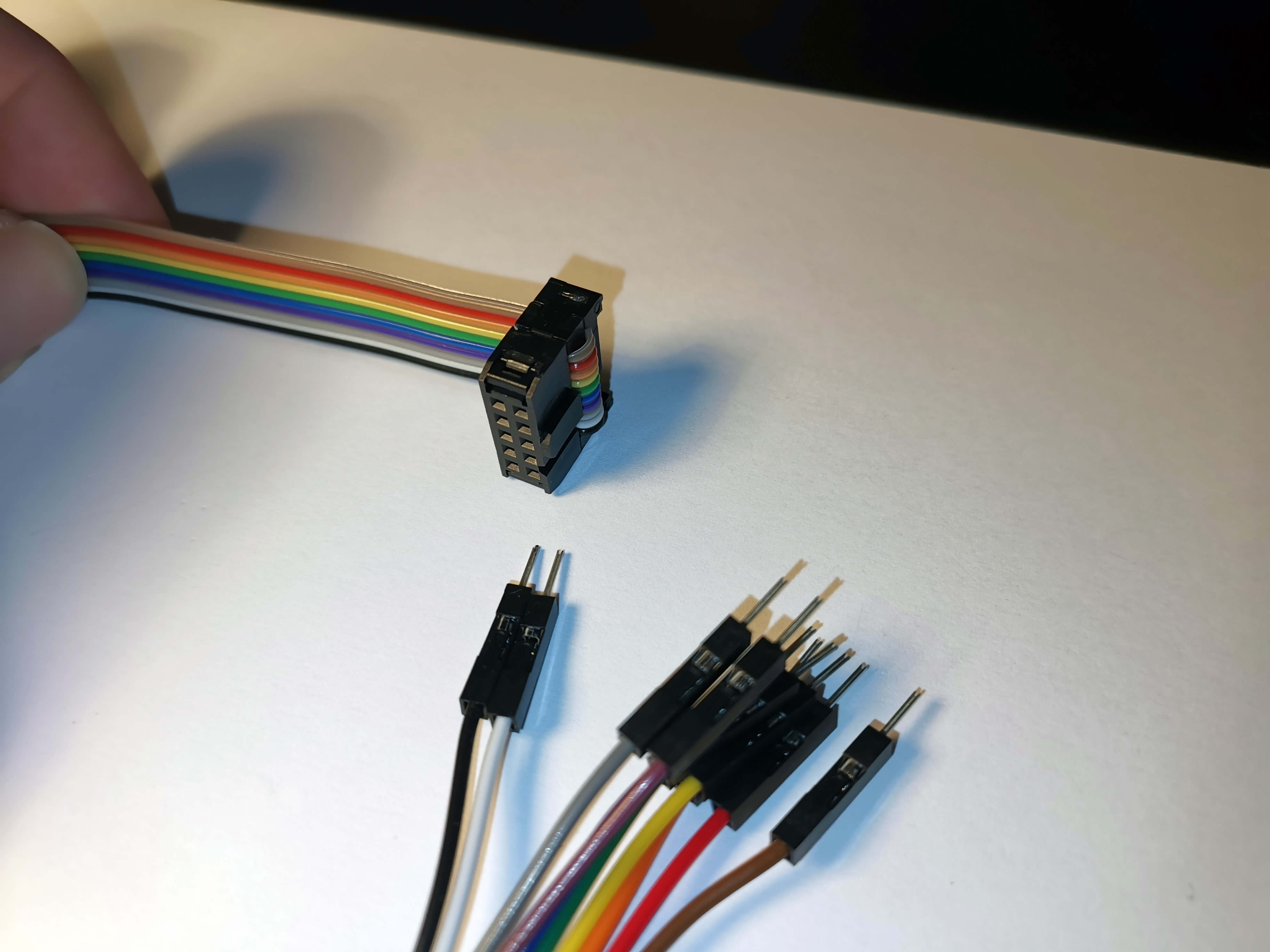
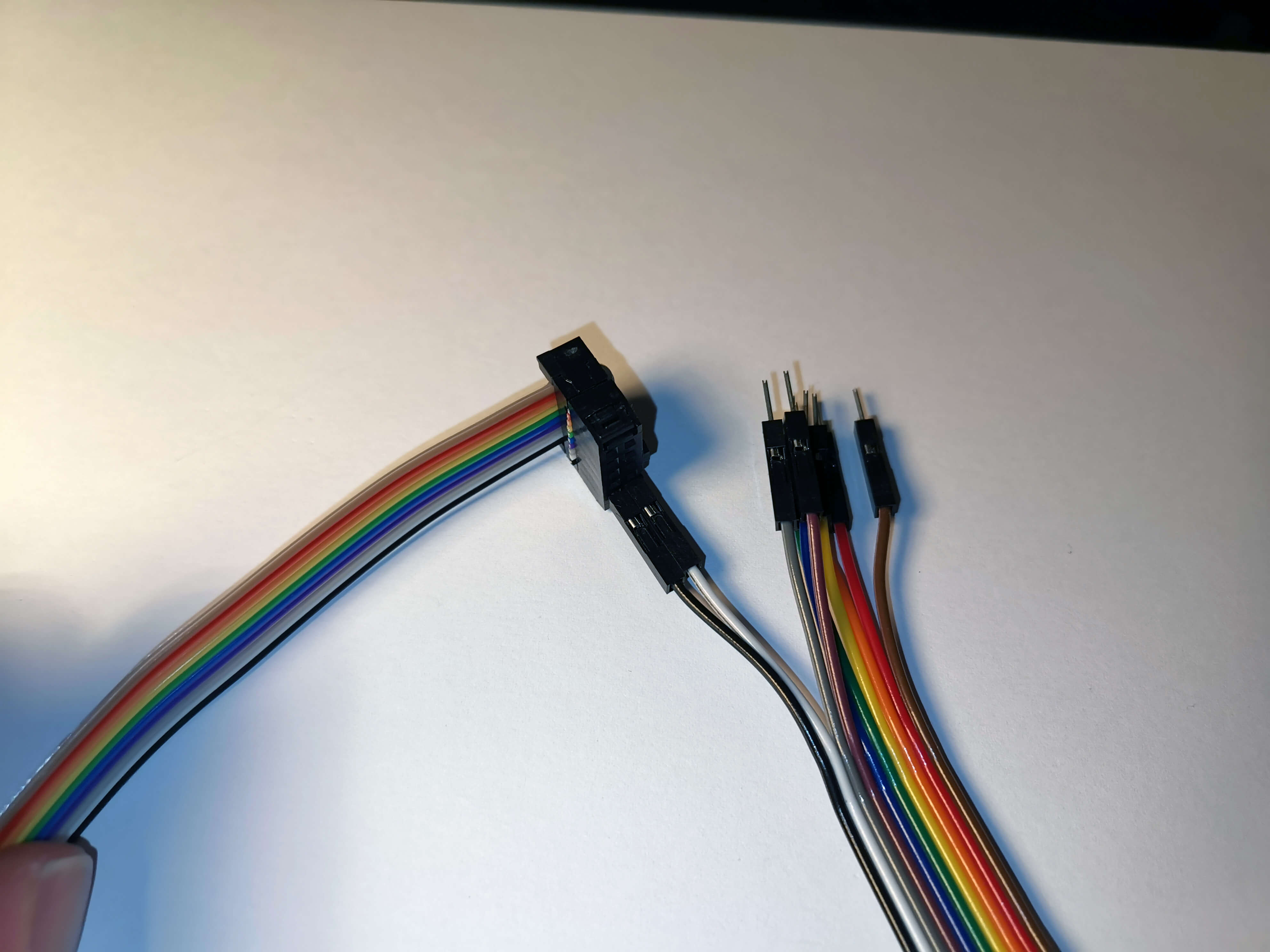
Next, insert the Grey and Purple cables as shown.
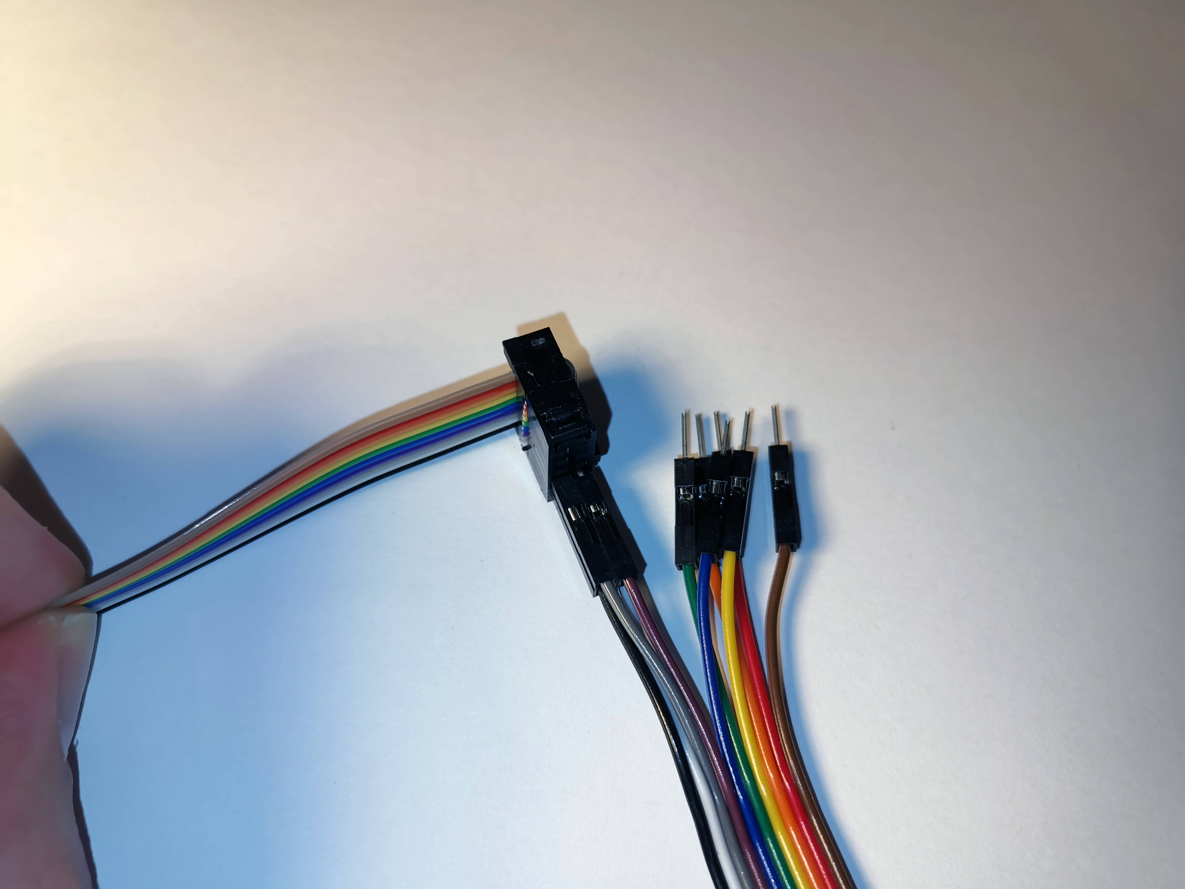
Next, Blue and Green.
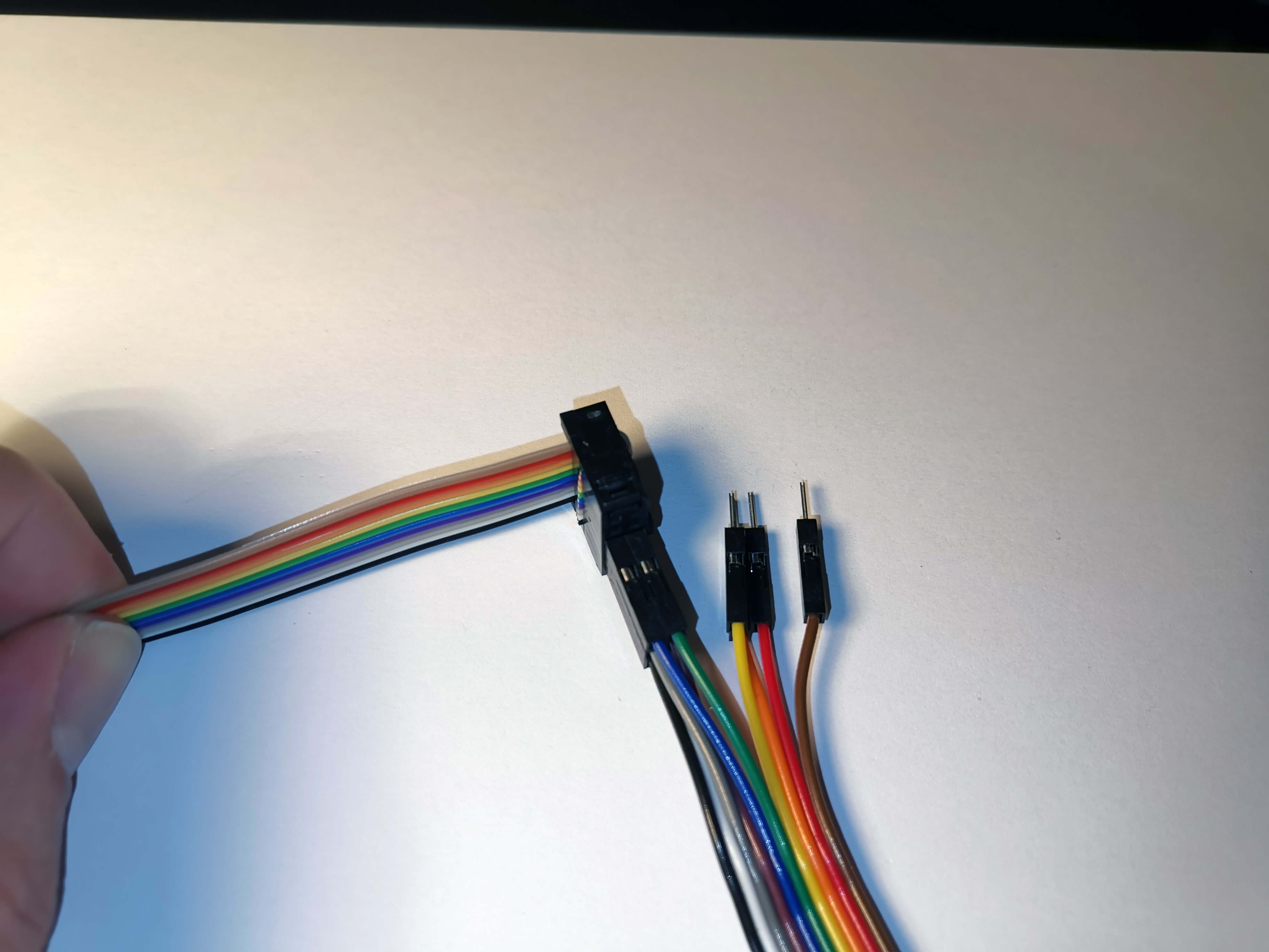
Next, Yellow and Orange.
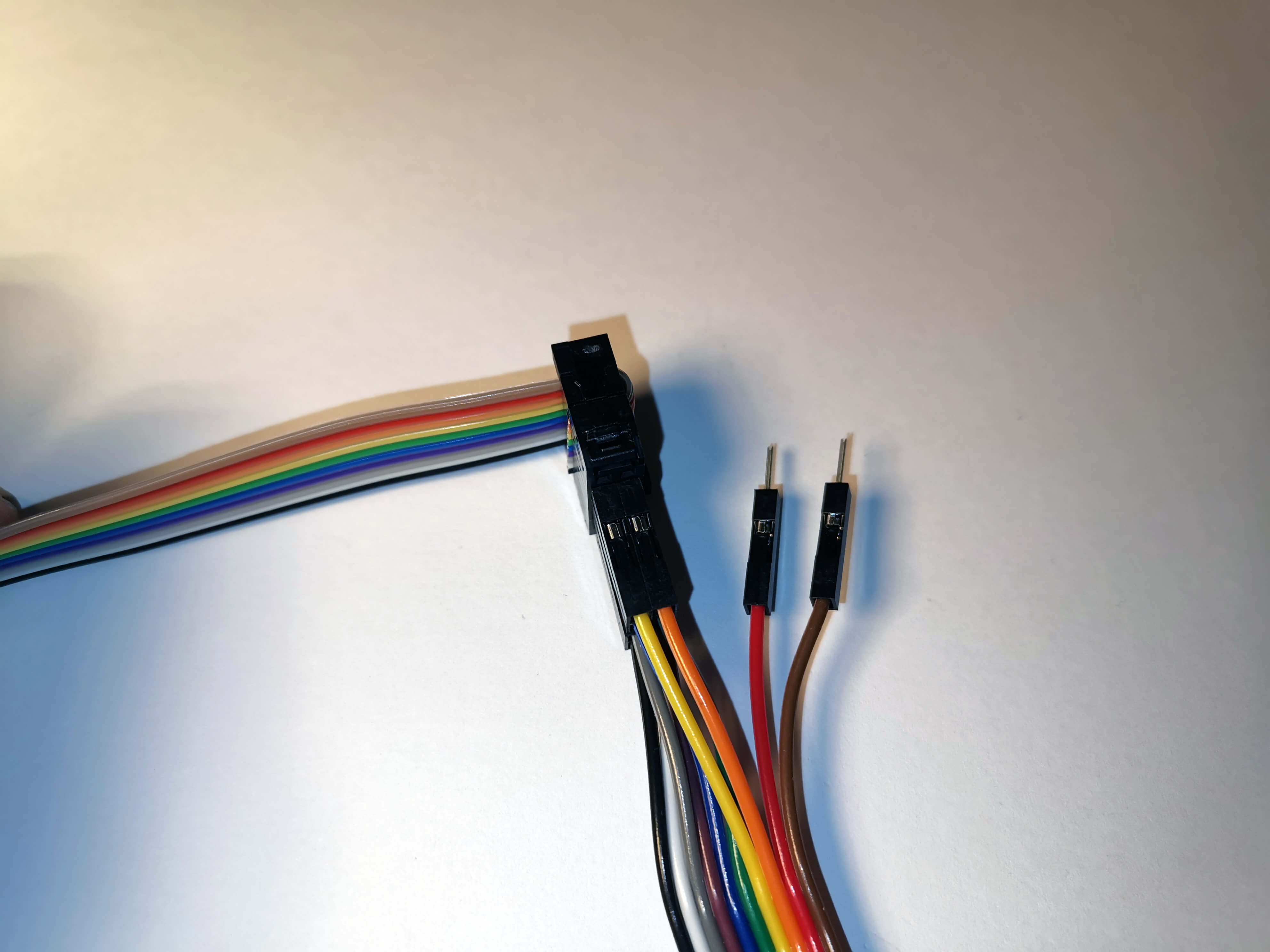
And last Red and Brown.
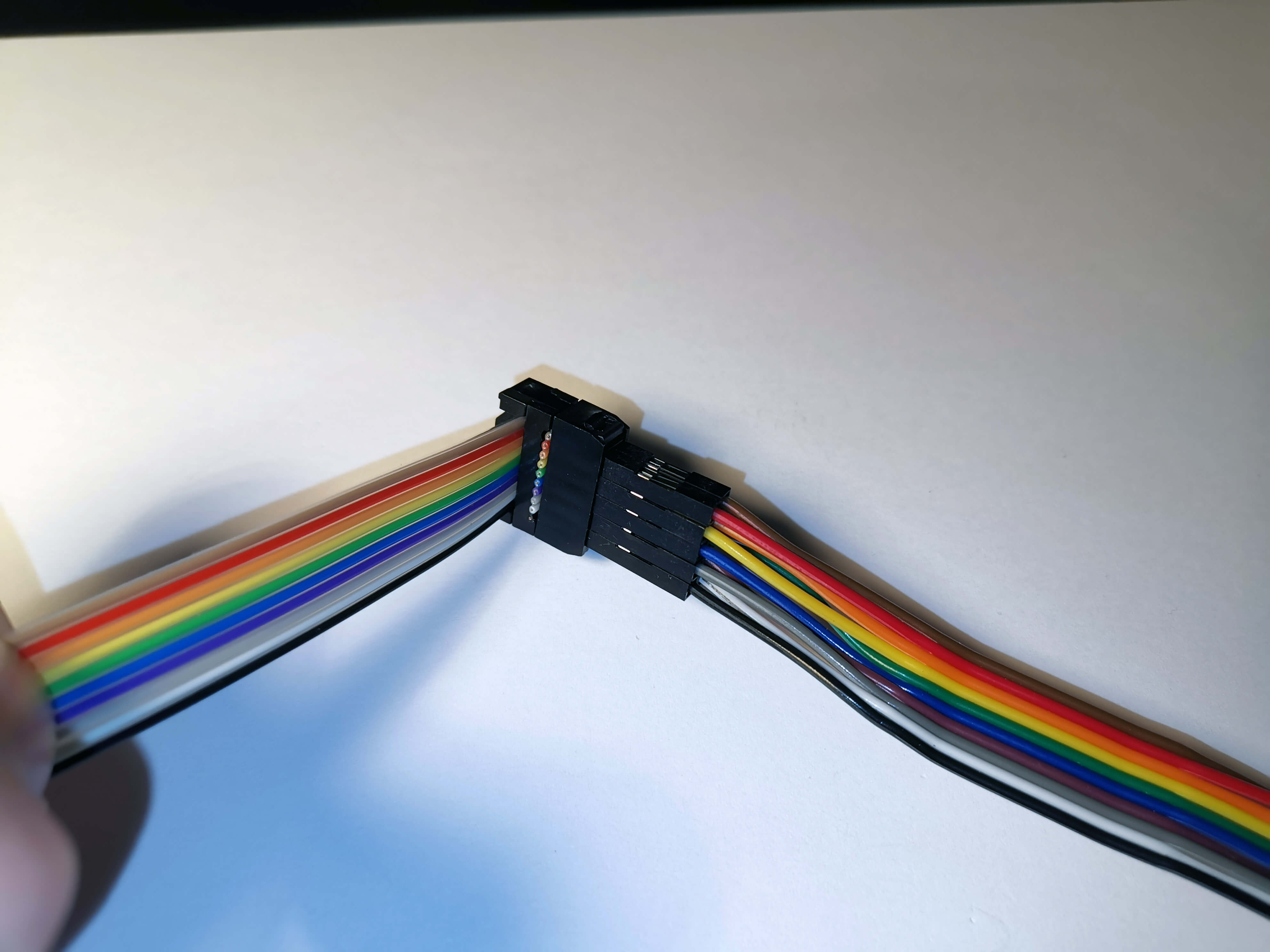
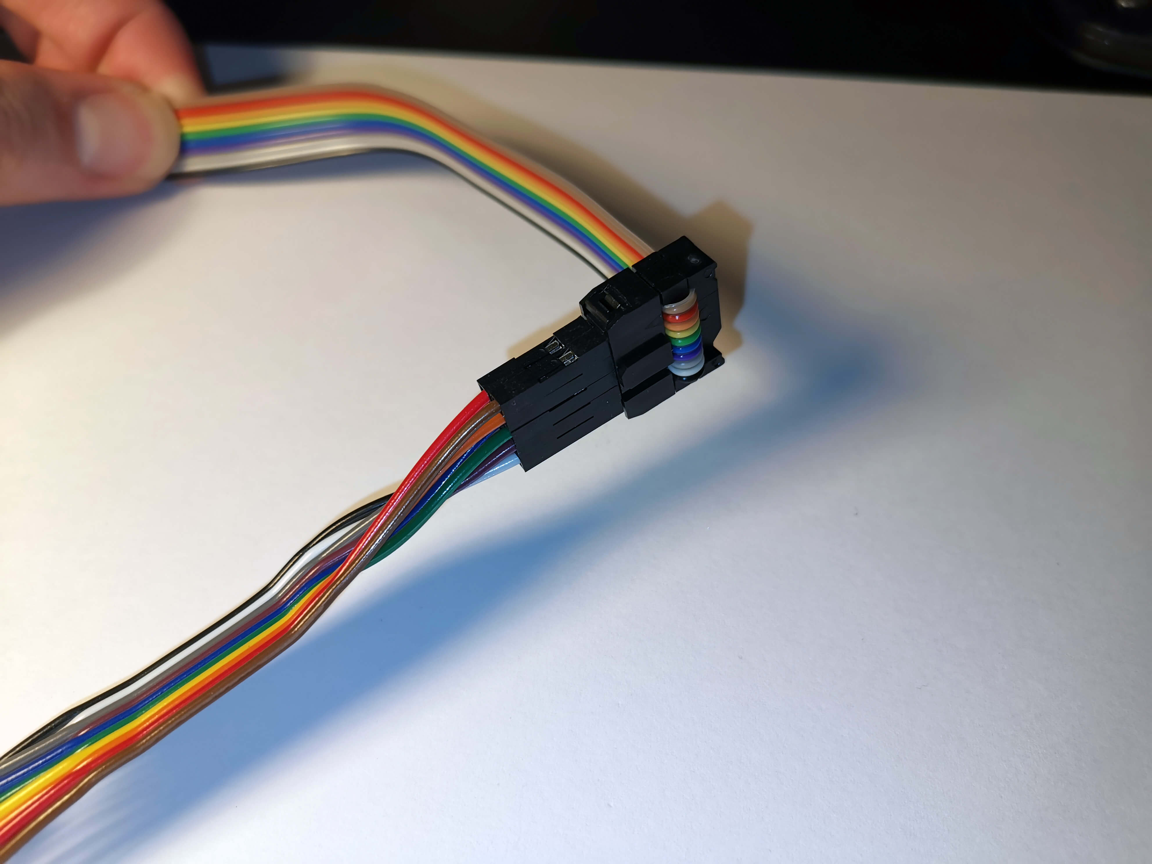
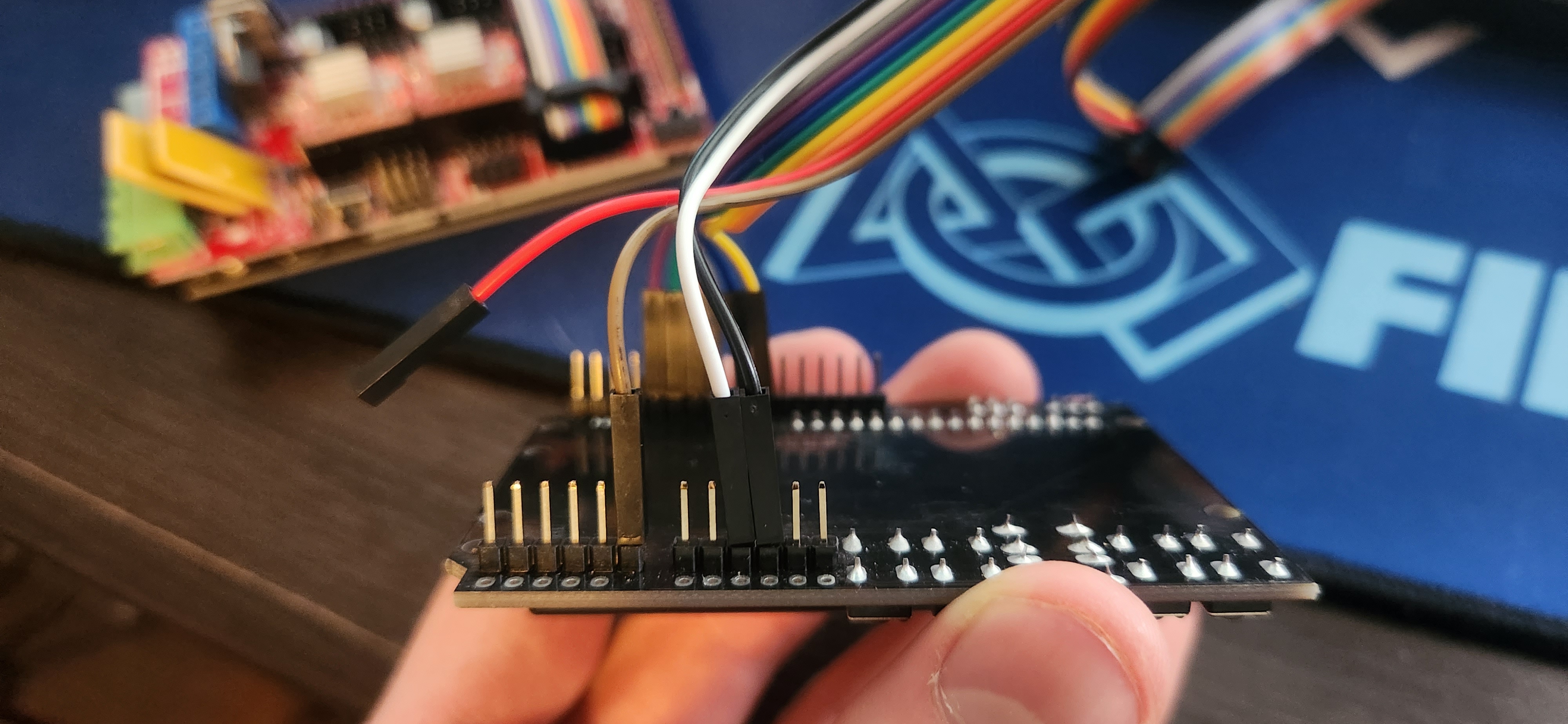
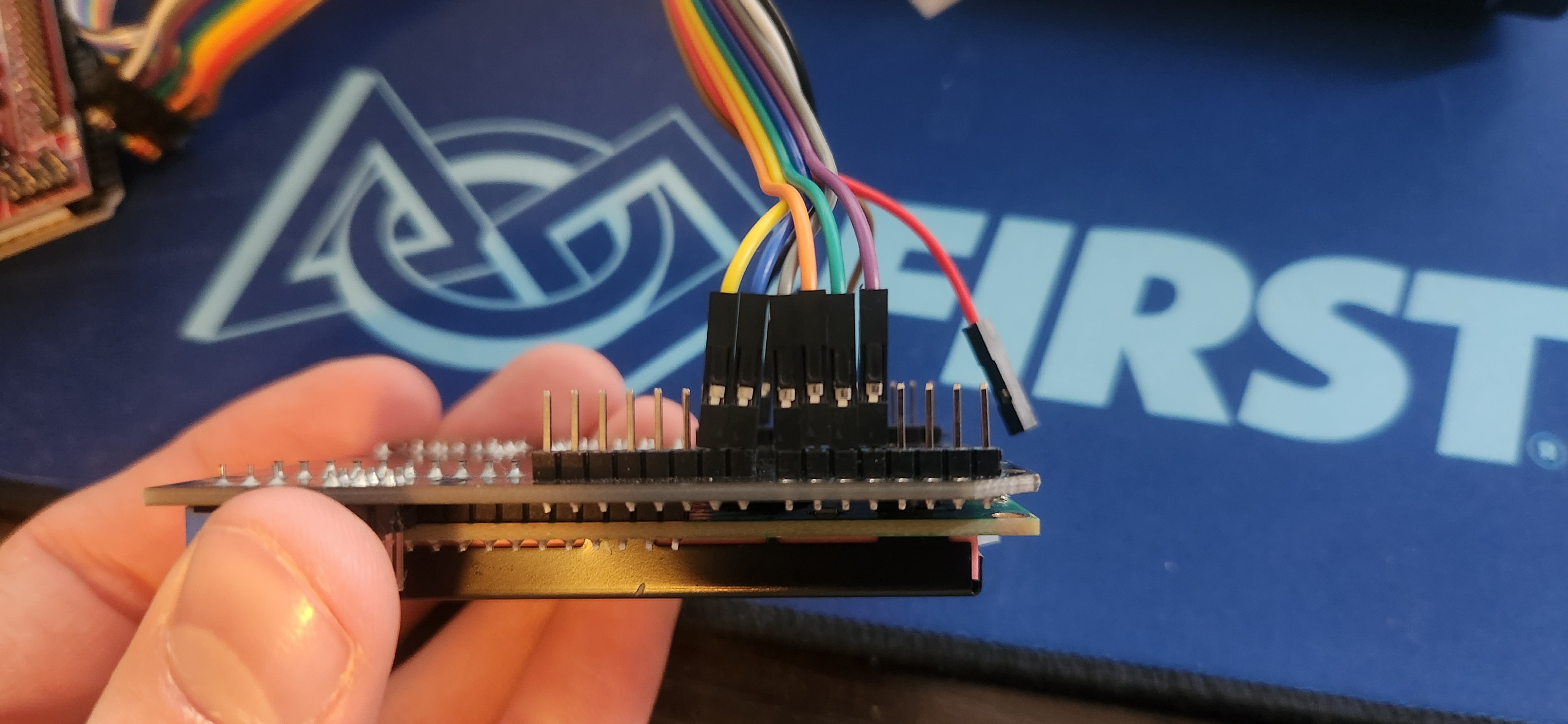
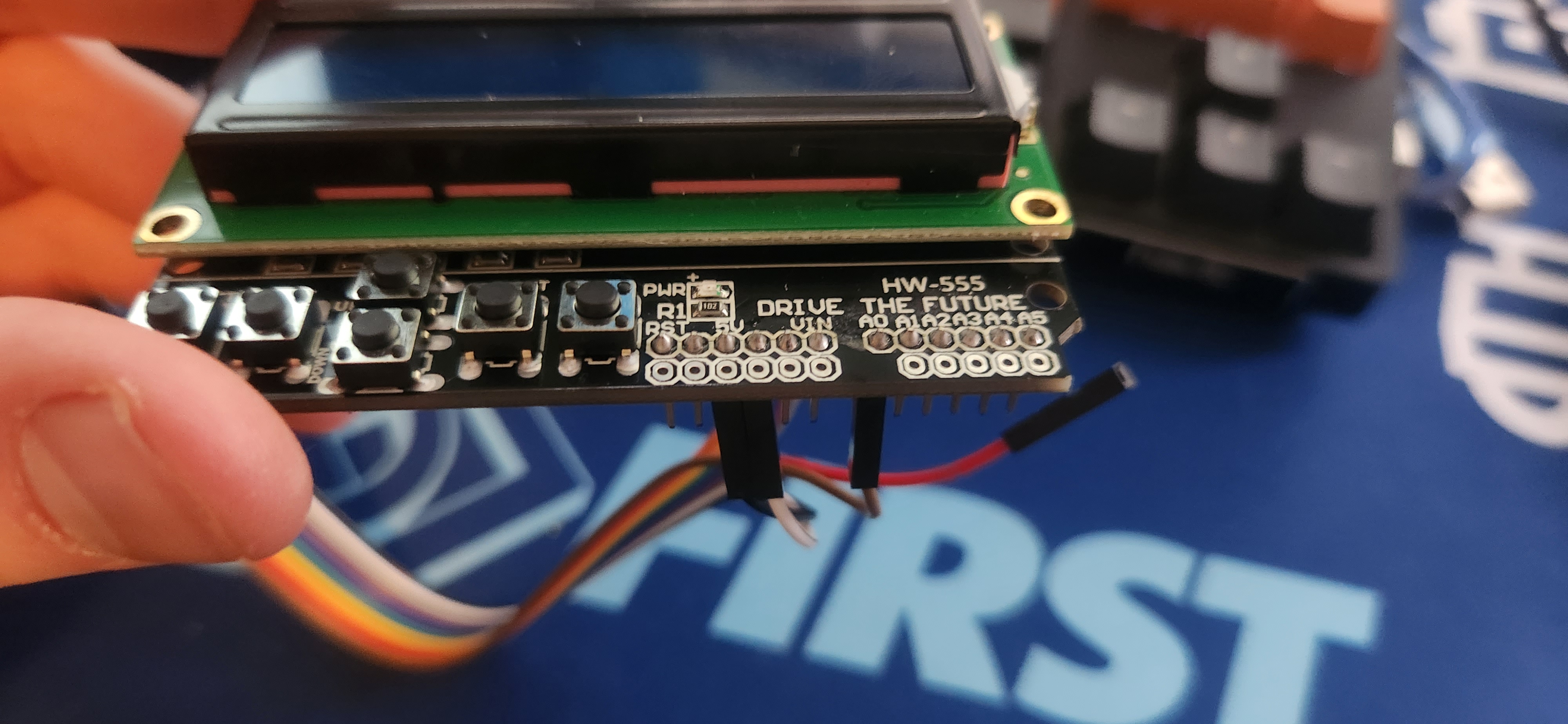
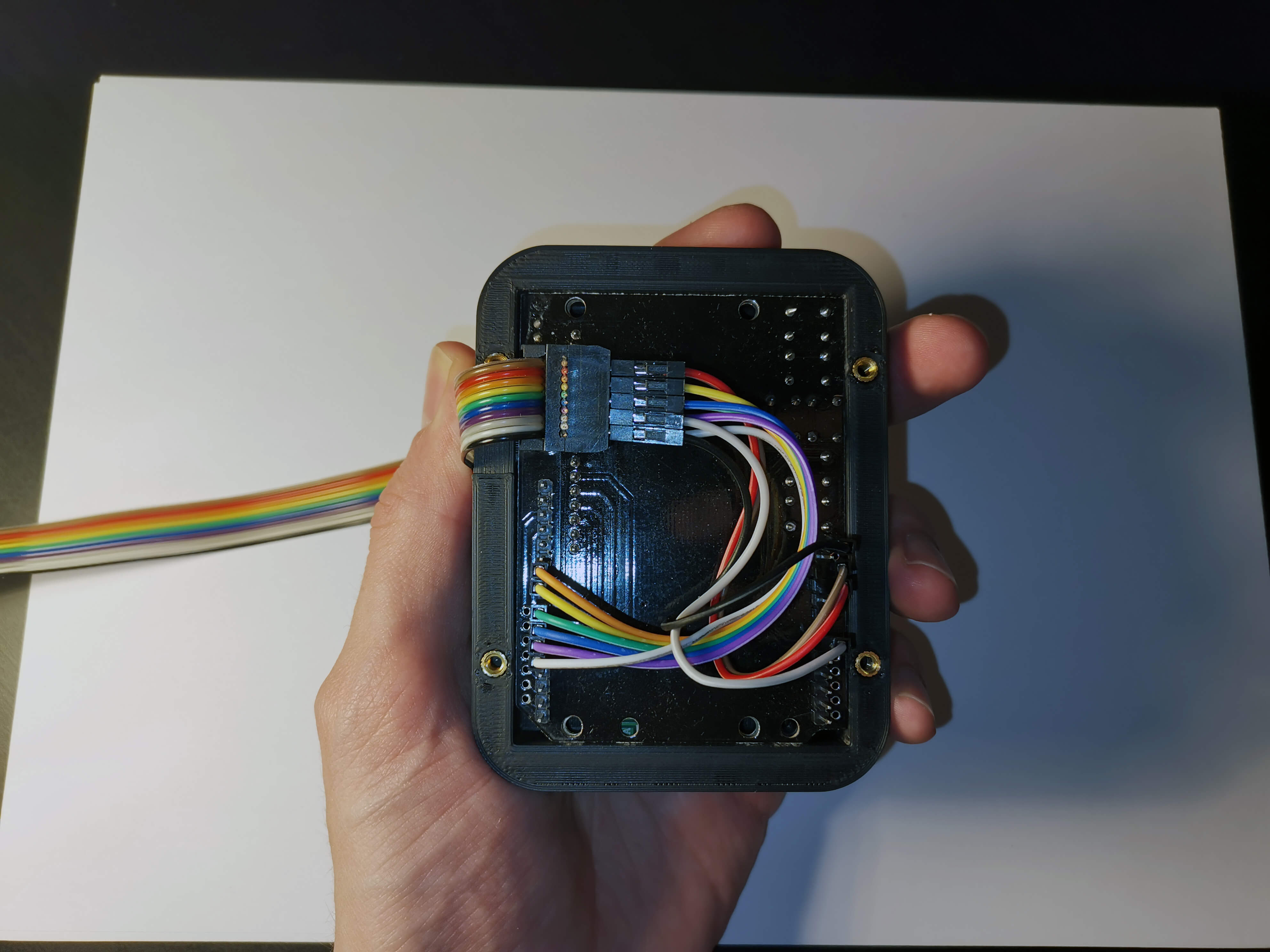
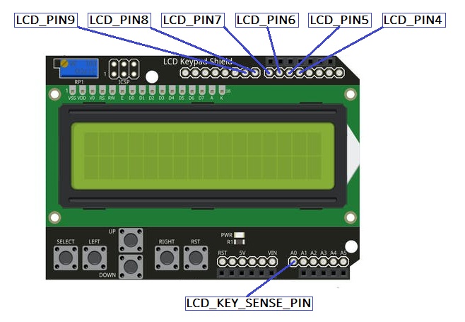
Next, connect the Dupont cables to the appropriate pins on the LCD, as shown below and in the pinout diagram at the top of the page.

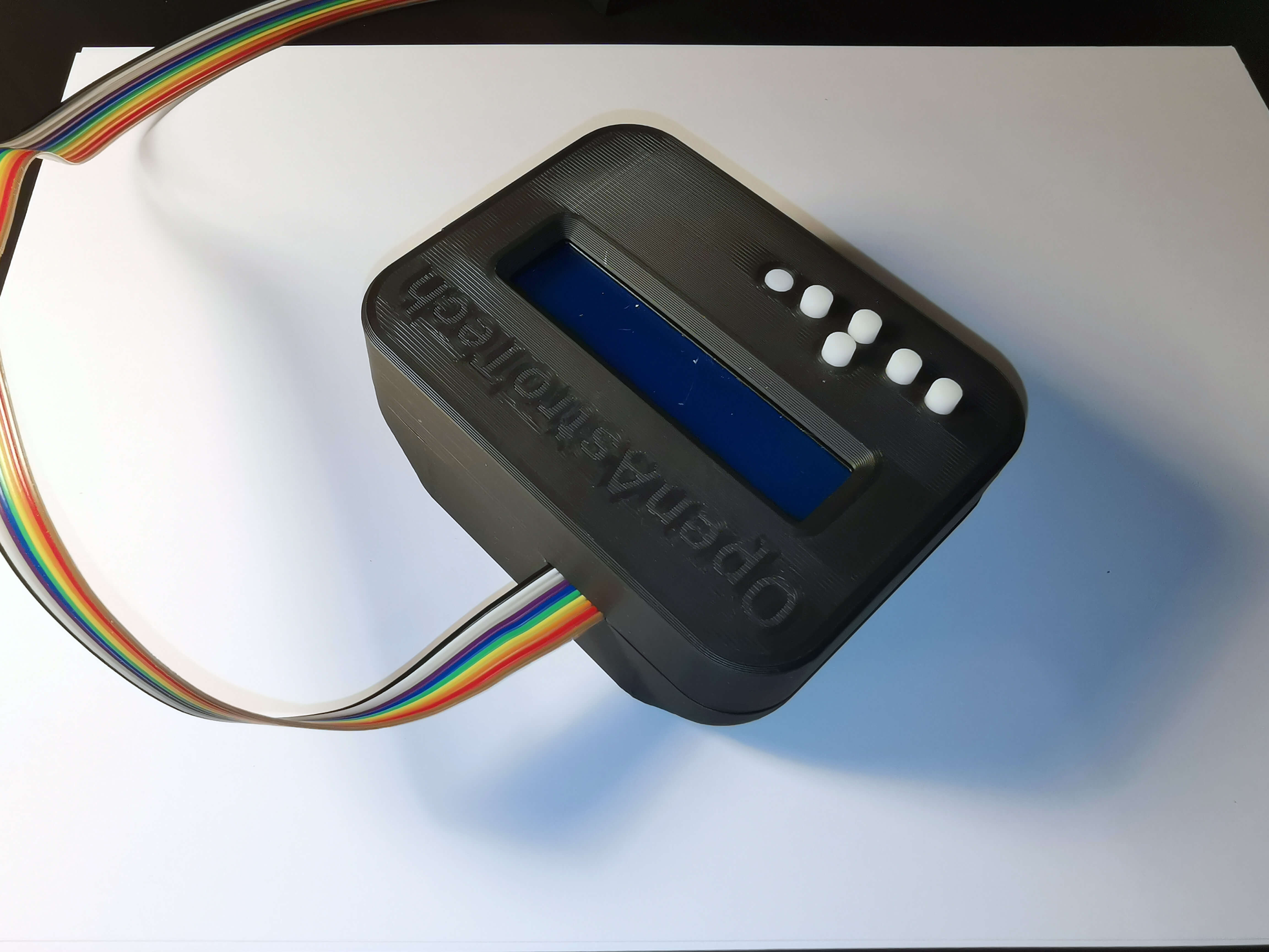
With the wires connected, the LCD can now be mounted into a case.
Note: Before sealing the enclosure, it’s recommended to power on the board and adjust the LCD screen contrast. Use the potentiometer located at the top left of the LCD to do this. If the contrast is not set correctly, the screen may appear blank during use. The potentiometer is inaccessible once the LCD is enclosed, so make sure to adjust it at this stage. For further details, see LCDMenu.
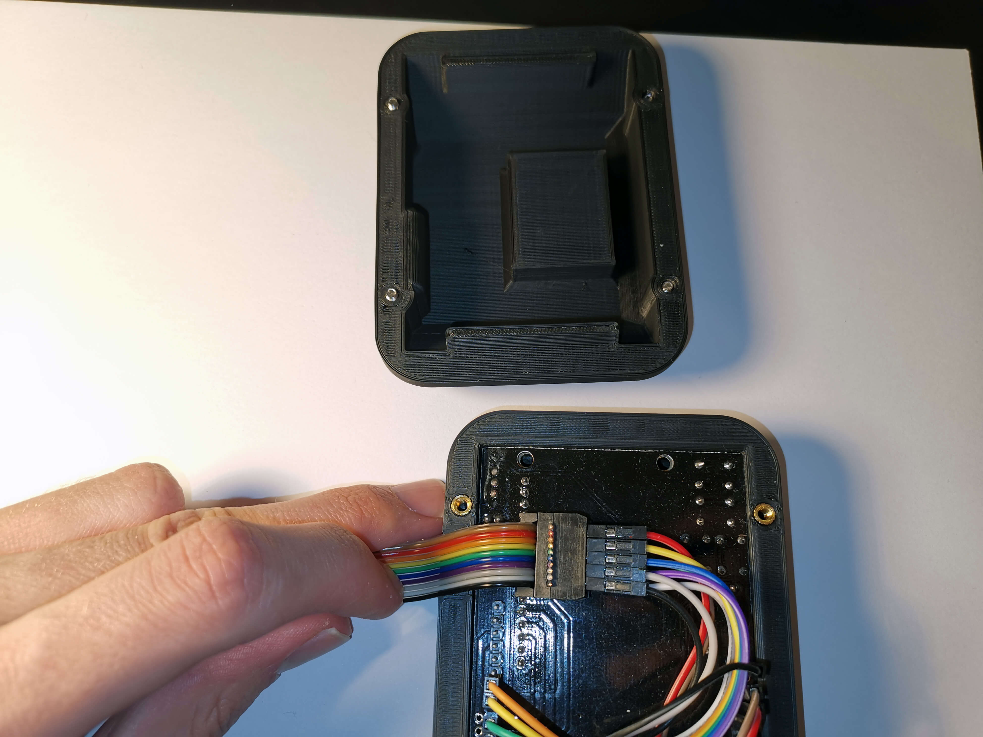
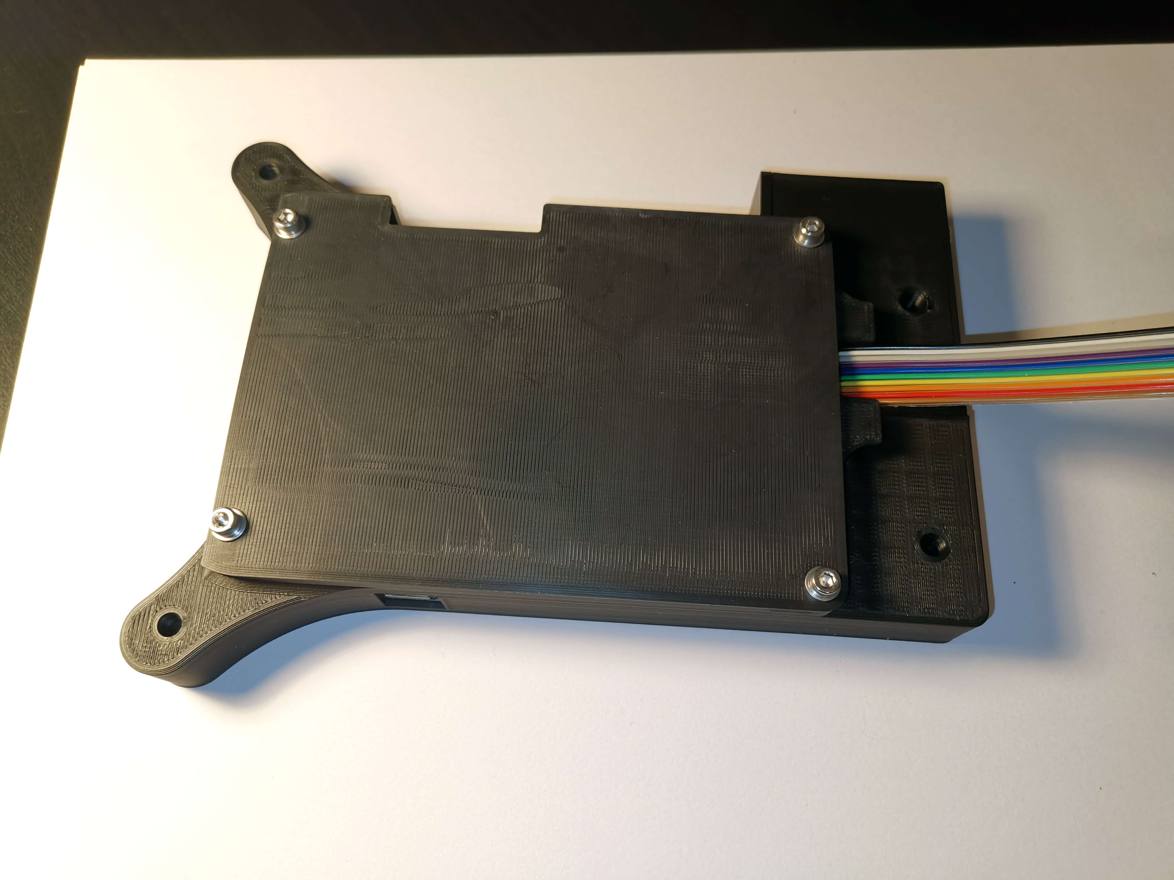
The images below demonstrate how to position and mount the LCD screen and associated wiring inside the LCD enclosure, as used with the Bottom Mounted MKS Case
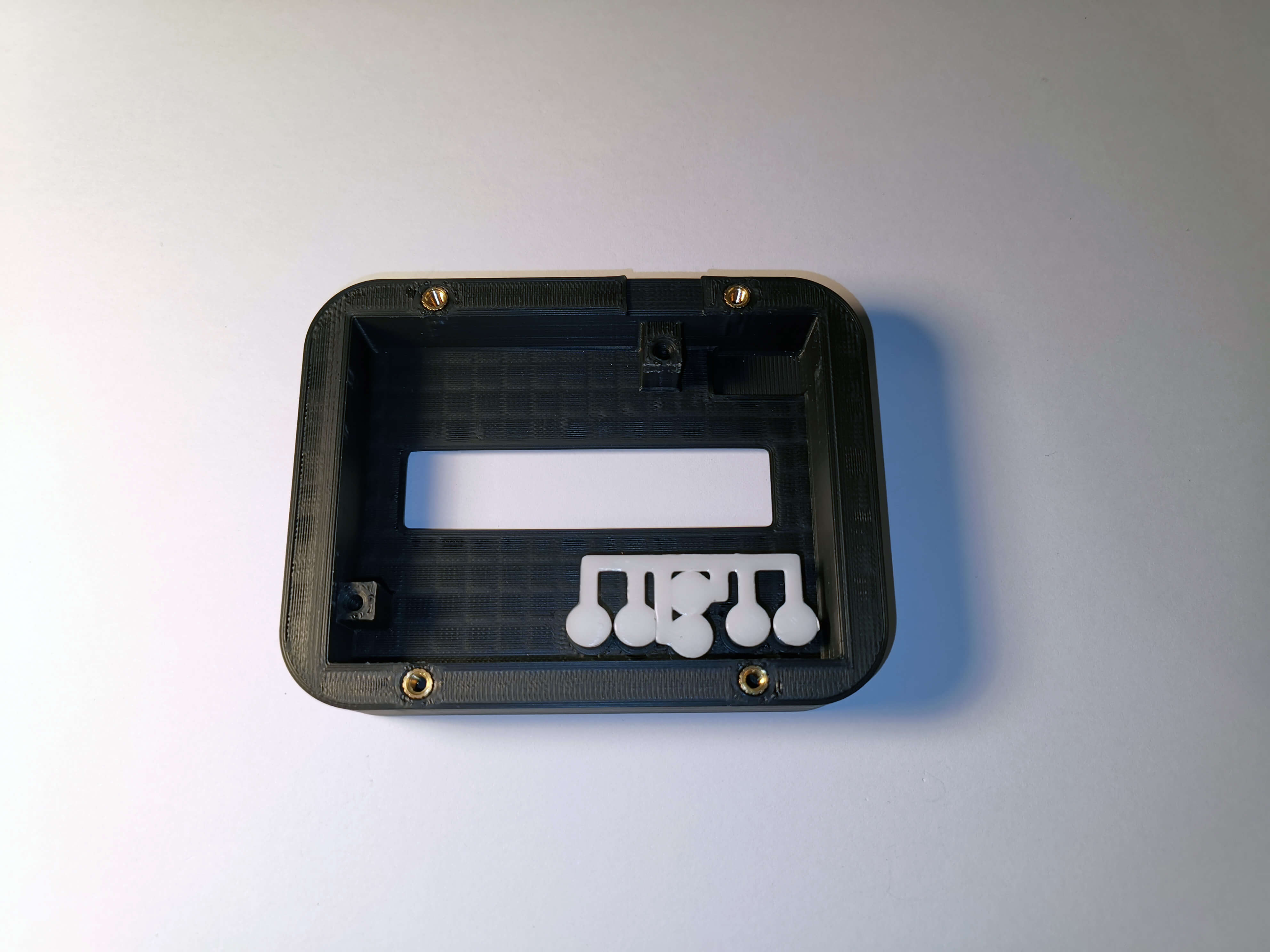
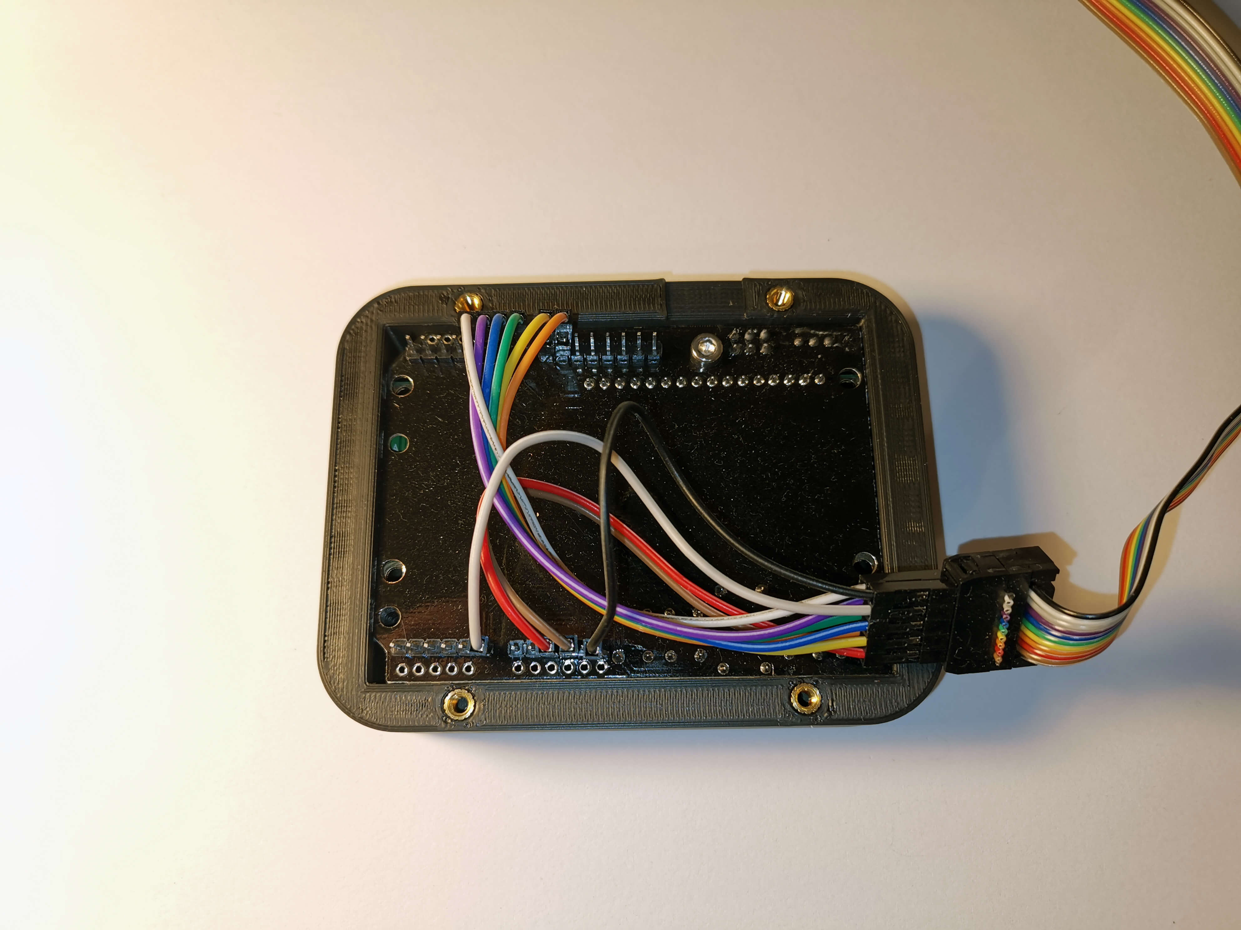
¶ MKS-side Termination
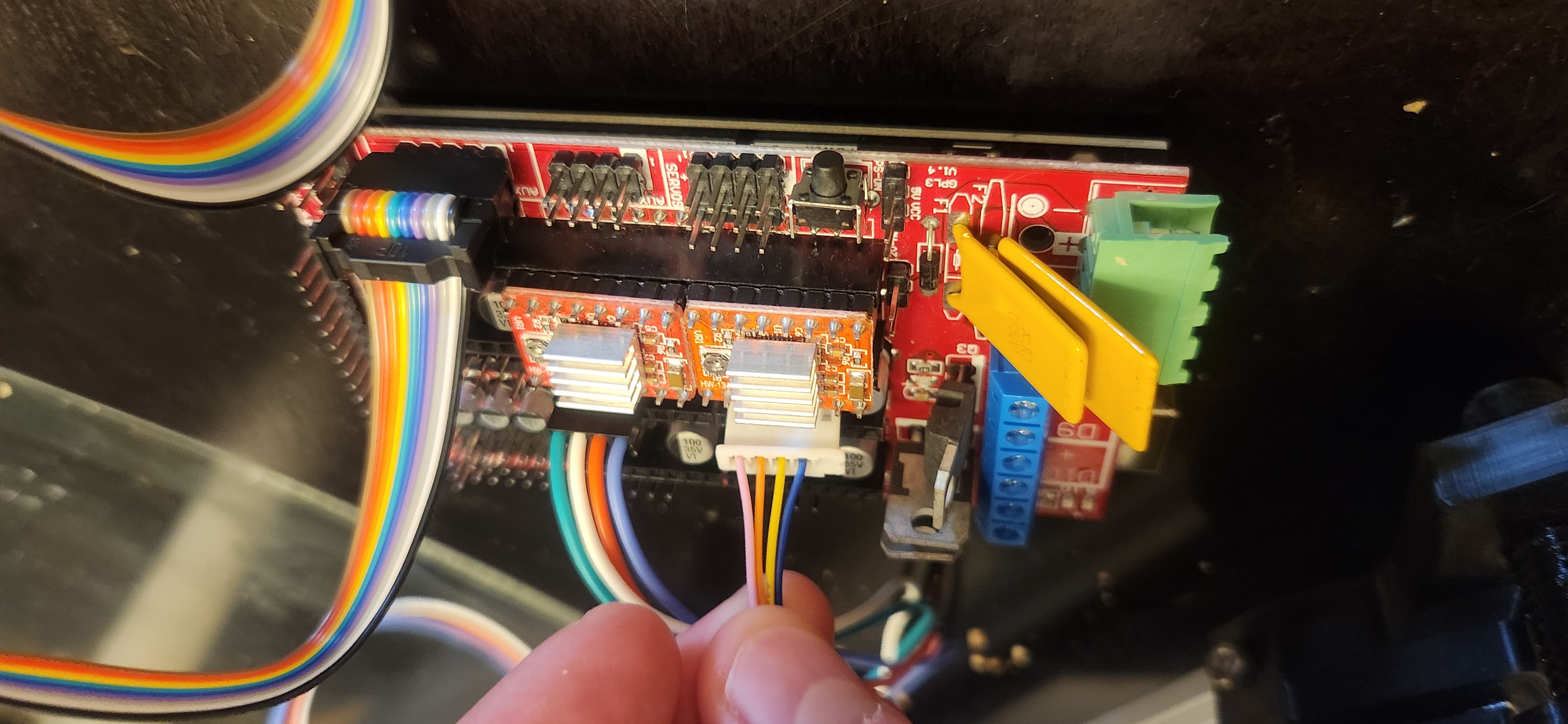
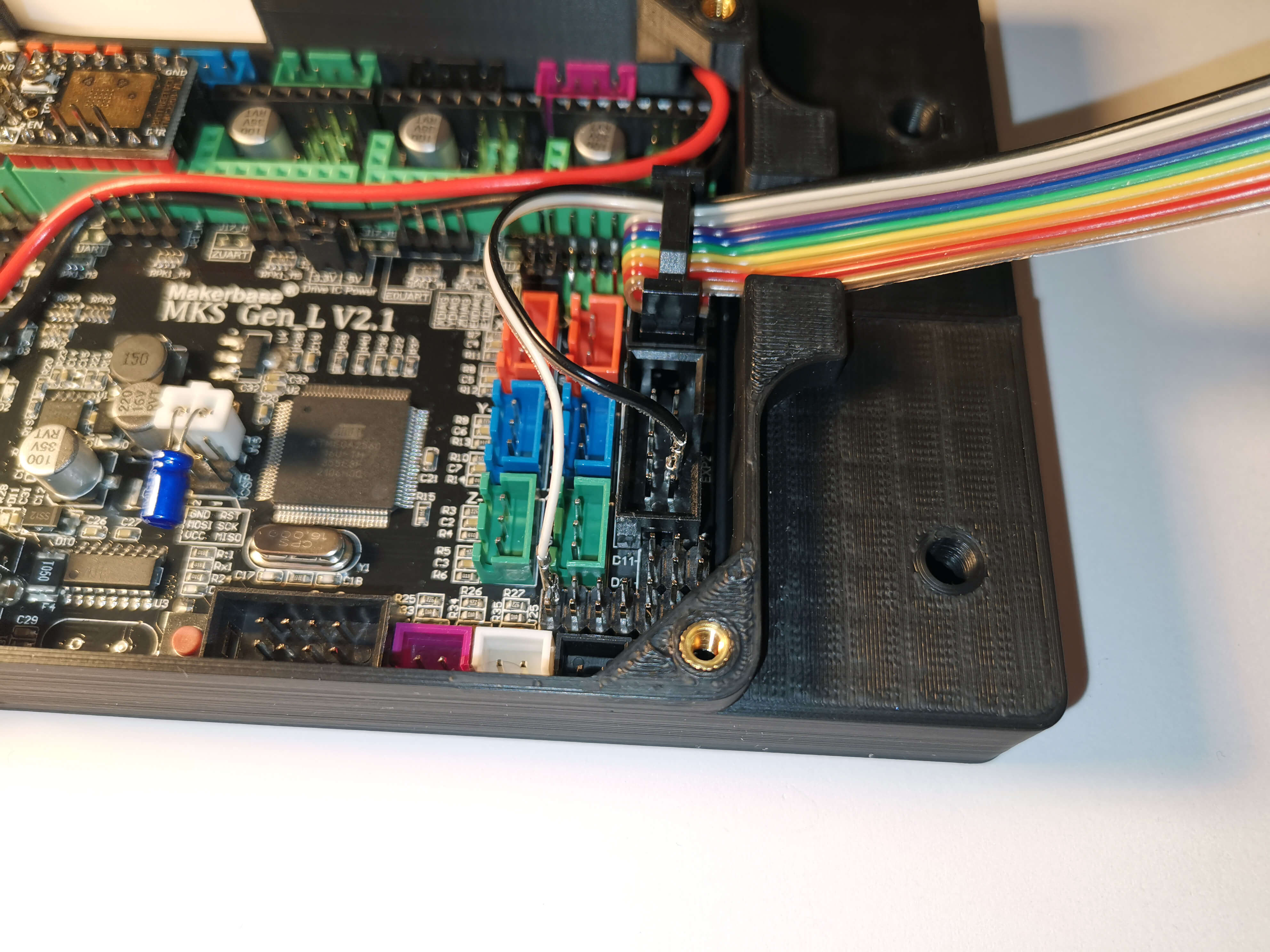
On the other side of the ribbon cable, seperate the black and white cable. Seperate about 7-8cm.
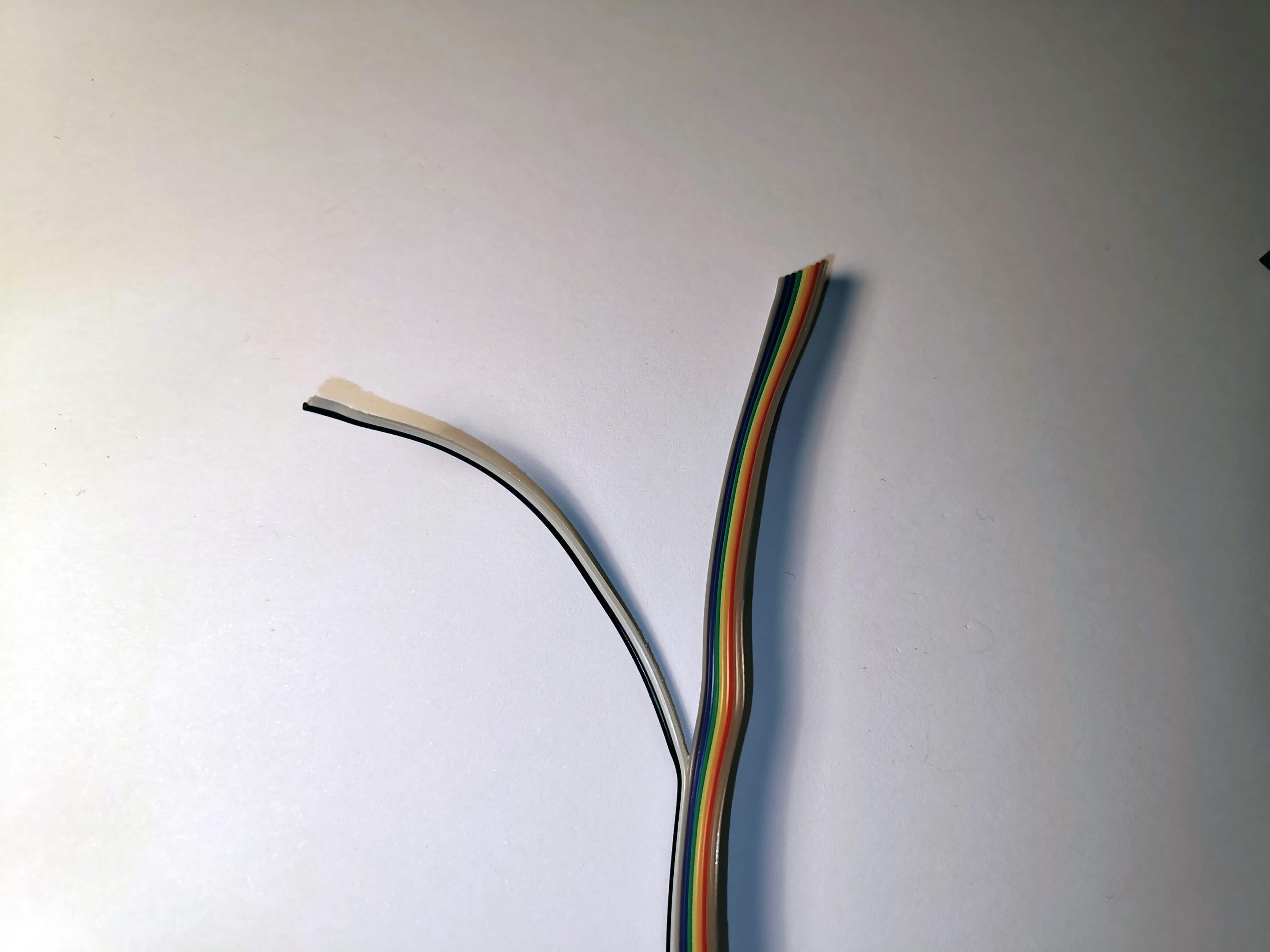
Insert the ribbon cable into a IDC connector in the way shown. Brown wire on the right side, little notch facing away from the cable. Do not insert the black and white cable.
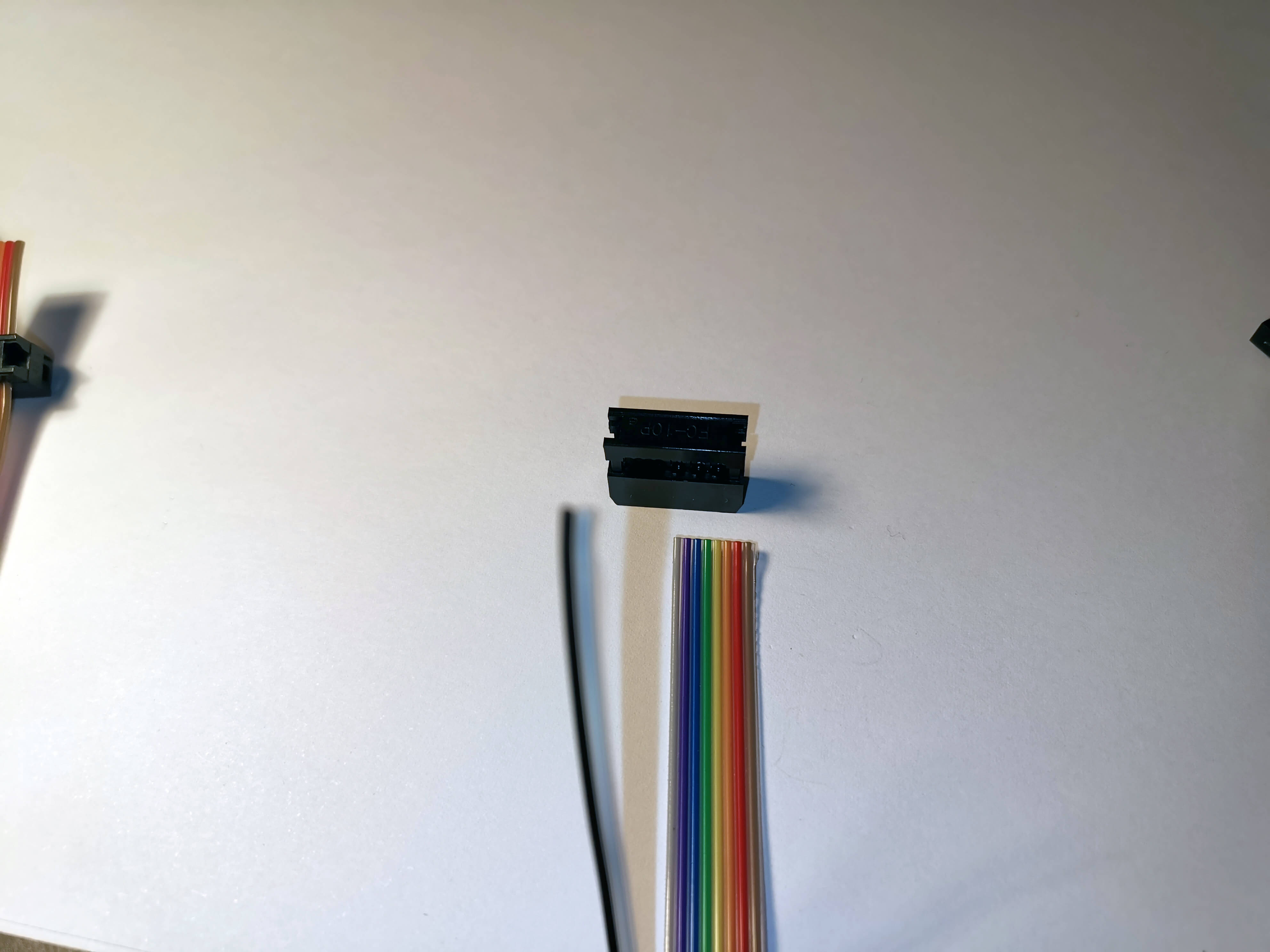
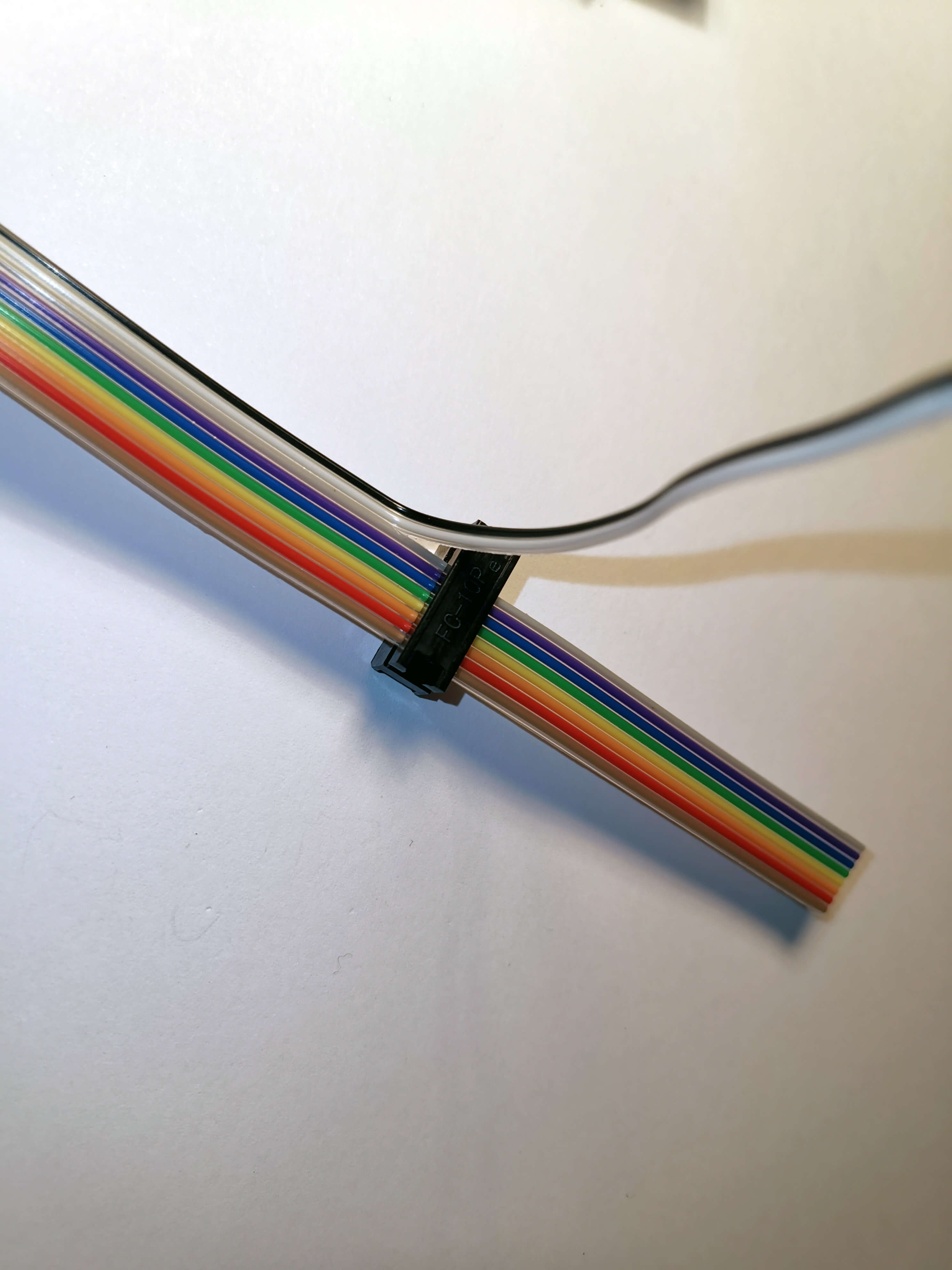
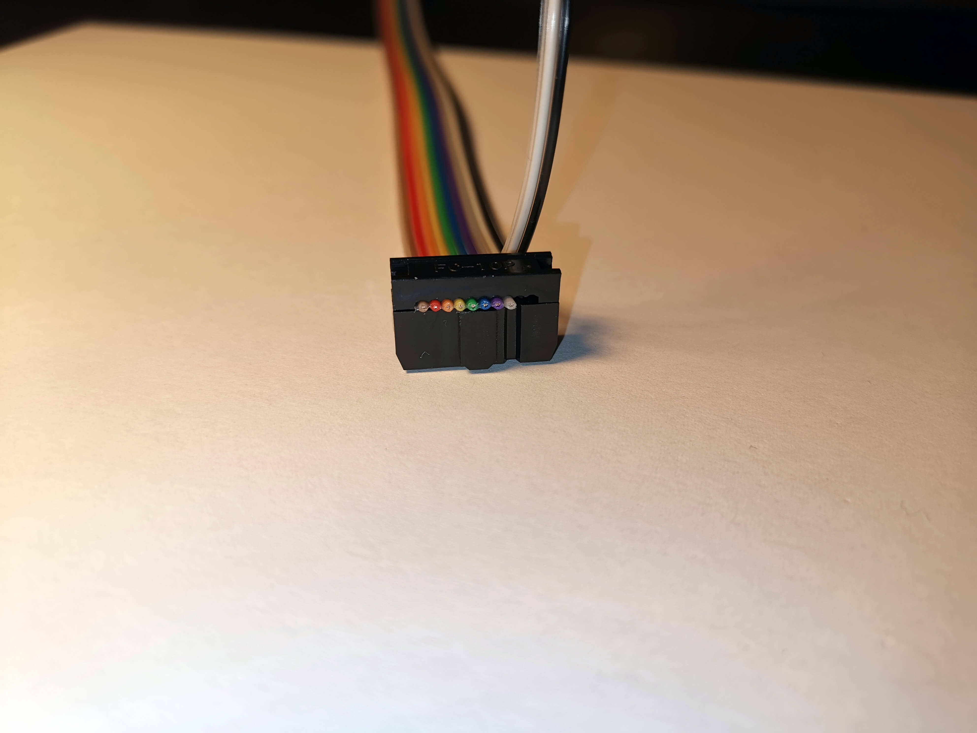
Strip the isolation from the black and white cable. Crimp either a JST or dupont connector to them. You don't need the plastic connector.
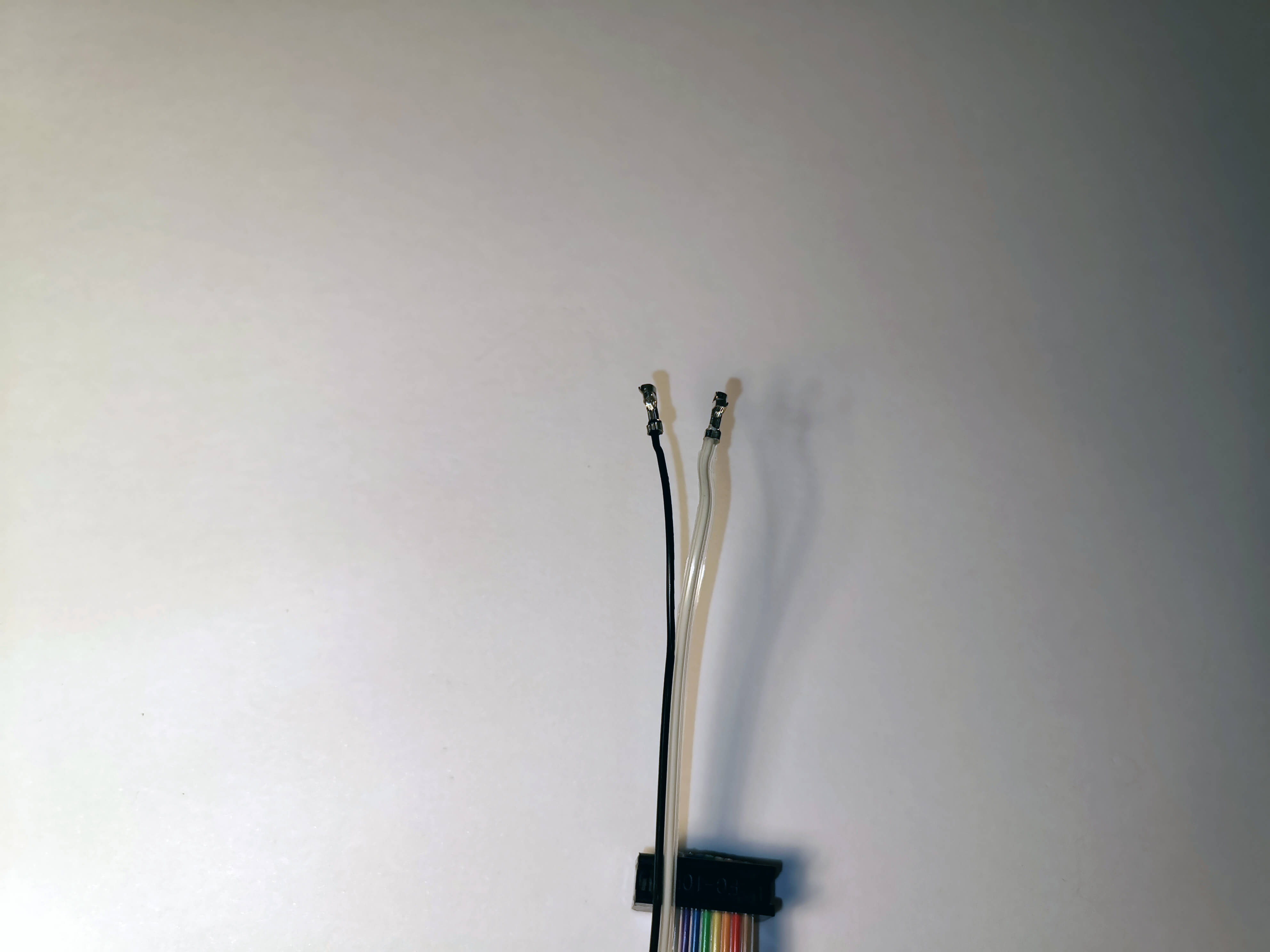
Note: For the MKS V1.0, the white cable is as follows:
| Pin Name | MKS Pin |
|---|---|
| LCD_KEY_SENSE_PIN | 65 |
Refer to the pinout here for reference.
¶ RAMPS-side Termination
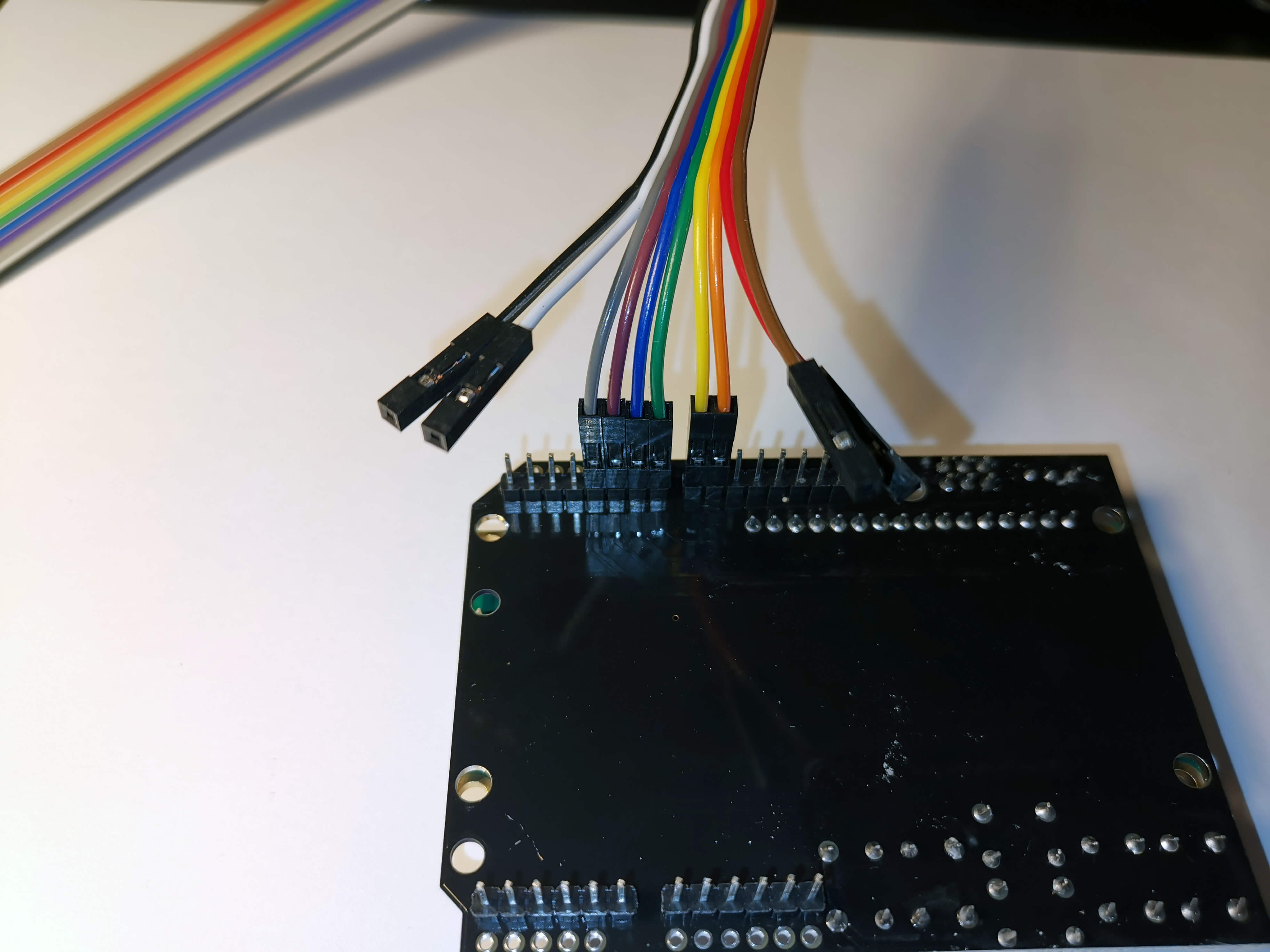
Separate the ribbon cable and add dupont connectors to each wire. Terminate on the RAMPS board as follows:
| Pin Name | RAMPS Pin | Color |
|---|---|---|
| LCD_PIN4 | 63 | Purple |
| LCD_PIN5 | 40 | Green |
| LCD_PIN6 | 42 | Orange |
| LCD_PIN7 | 59 | Grey |
| LCD_PIN8 | 64 | Blue |
| LCD_PIN9 | 44 | Yellow |
| LCD_KEY_SENSE_PIN | 65 | Brown |
| 5V | 5V | Black |
| GND | GND | White |
Note: The RAMPS board does not have a RST pin available. The ground pin is unlabeled on many 1602 LCD displays but is the pin to the right of the 5V pin (if viewing the LCD from the front).
RAMPS Pinout:
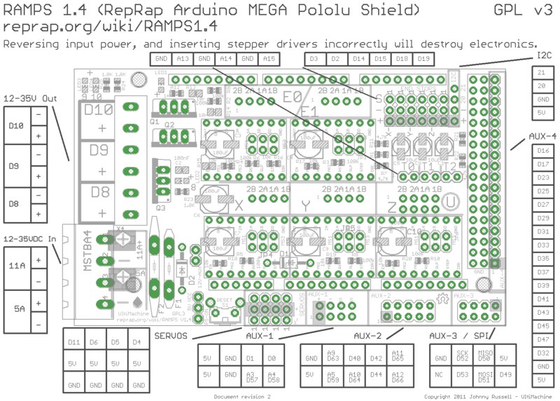
All of the relevant pins are in the AUX-2 block in the lower middle. The
10-pin colored ribbon cable can easily connect to this block.
LCD Pinout:
Pictures illustrating RAMPS wiring colors:
NOTE: The red wire connects to the RESET button on the LCD board, however RAMPS doesnt have a pin for it, so leave it disconnected.
