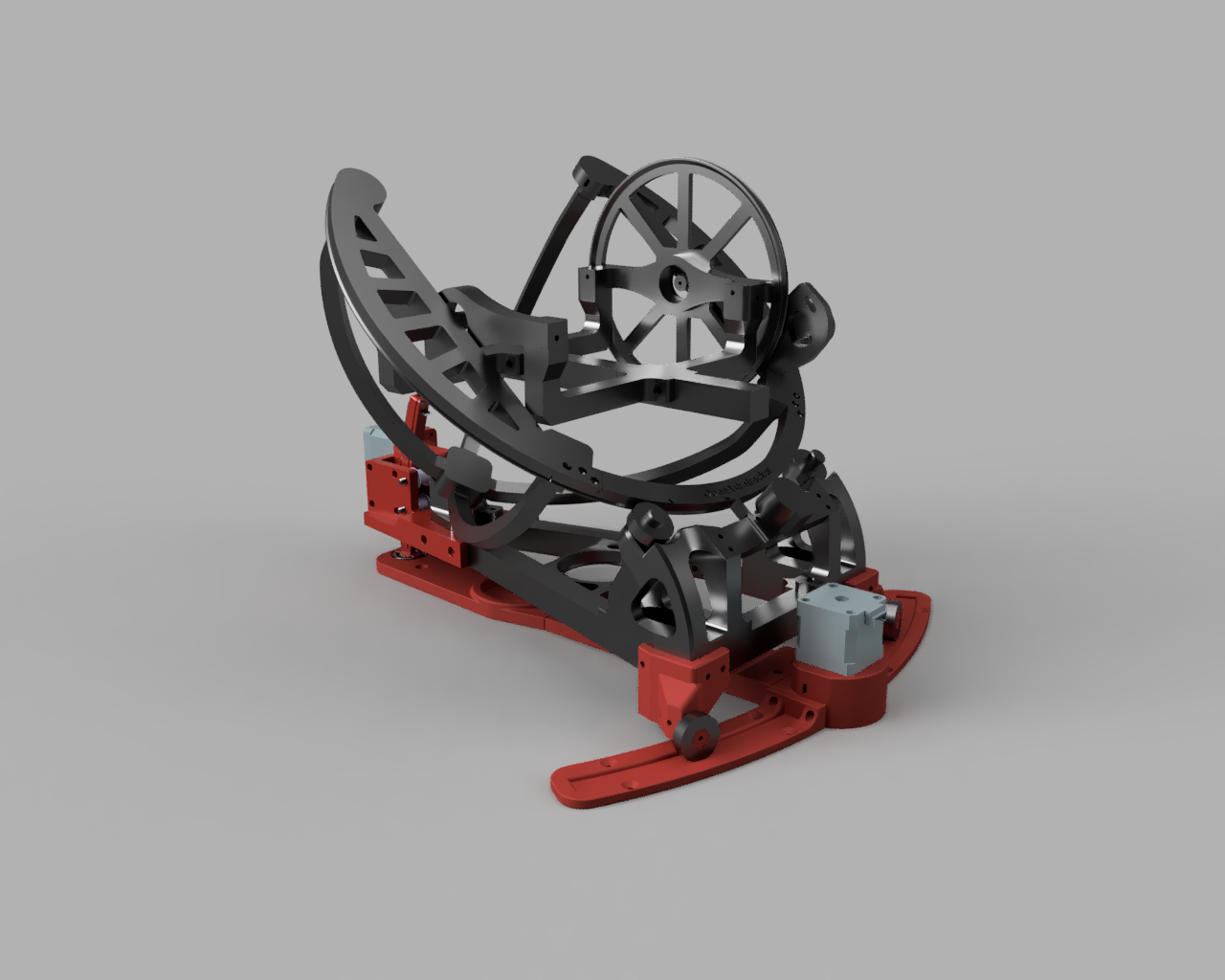
The AutoPA V2 upgrade is system that allows motorized polar alignment by turning the Azimuth and Altitude using two additional stepper motors.
AutoPA works using NINA's Three-Point Polar Alignment or Sharpcap Pro's Polar Alignment Routine to determine the error correction needed and the software handles automatically adjusting the mount to bring it in alignment with the pole.
If you are using OATControl, the process is automated and you don't need to do anything (after you have enabled NINA Logfiole Monitoring).
If you can't use OATControl, there is an older Python script that can be used instead. Here are two video examples by Discord user @Elessar showing AutoPA achieving polar alignment using both Sharpcap 4.0 and N.I.N.A.:
Sharpcap 4.0 Example
N.I.N.A. Example
Each axis can also be manually controlled via OATcontrol's minicontrol panel if you wish to make manual adjustments.
AutoPA has a range of +3/-15 deg altitude, depending on which track is used (short track is 6 deg less range than the long track). The +3 might also be limited by things like undermounted MKS cases, etc as they may collide with the bottom framing.
Note: Since the negative range is higher, you should choose the variation in the Parts Picker that is higher than your latitude. If you live at 23N, choose the 30 degree version, etc.
¶ Parts List
¶ Electronics
| Type | Specification | Quantity |
|---|---|---|
| Stepper Motor | NEMA17 0.9° or 1.8° (recommended) or 28BYJ-48 | 2 |
| Stepper Driver | TMC2209 (recommended) or generic stepper driver | 2 |
¶ Hardware
| Type | Specification | Quantity | Store Links |
|---|---|---|---|
| 6001 bearing | - | 3 | https://aliexpress.com/item/1636211921.html |
| 625 bearing | - | 2 | https://aliexpress.com/item/32951064437.html |
| Shaft | d=5mm, length >= 75 mm (sold as 100mm, it is optional to cut to length) | 1 | https://www.amazon.com/s?k=uxcell+5mm+x+100mm+304+stainless+steel+solid+round+rod+for+diy+craft+-+5pcs&crid=RMOGMF2KRFB2&sprefix=%2Caps%2C128&ref=nb_sb_ss_recent_1_0_recent |
| Toothed Pulley | GT2, w=6mm, ID=5mm, 16T | 2 | https://www.aliexpress.com/item/32621920304.html |
| Idler Pulley | Toothless, w=10mm, ID=5mm, 20T equivalent | 2 | https://www.aliexpress.com/item/32817328238.html or https://www.amazon.com/dp/B07BPHRSN5?psc=1&ref=ppx_yo2ov_dt_b_product_details |
| Idler Pulley | Toothless, w=6mm, ID=5mm, 20T equivalent | 2 | |
| Worm Screw + Gear | Brass, ID=5mm, 0.5mm module Screw: 1T Wheel: 40T |
1 gear + 1 wheel (usually sold as a set) | https://www.amazon.ca/dp/B07G54YQL4 https://aliexpress.com/i/32930524746.html |
| Belt | GT2, w=6mm | ~ 500mm | |
| Belt tension spring | GT2 | 2 | https://www.aliexpress.com/item/32650610030.html |
| M3 bolts | Various sizes (mostly 12mm) | ~ 20 | |
| M3 nuts | - | 14 | |
| M4 bolts (if using 28BYJ steppers) | length=8mm | 4 | |
| M5 bolt | length=30mm | 2 | |
| M5 nut | - | 2 |
¶ Printed Parts
Note: Remember to print the rollmounts corresponding to the next highest number from your latitude. If you are going to use the OAT at 32N, choose the 40 degree version in the Parts Picker.
https://github.com/OpenAstroTech/OpenAstroTracker-Addons/tree/master/AutoPA
Note: be very selective about how supports are placed when printing. Some holes are very difficult to remove the support structure from.
| Filename | Quantity |
|---|---|
| 13_rear_AltAz_mount.stl | 1 - Replaces default rear mount |
| Alt_gearbox.stl | 1 |
| Alt_track.stl | 1 |
| Alt_Track_Short.stl | 1 - for 50deg roll mount |
| AutoPA_mount_left_2020base.stl | 1 - Replaces default left mount |
| AutoPA_mount_right_2020base.stl | 1 - Replaces default right mount |
| Az_motor_mount.stl | 1 |
| Az_pivot_frameA.stl | 1 |
| Az_pivot_frameB.stl | 1 |
| Az_slide_frame_left.stl | 1 |
| Az_slide_frame_right.stl | 1 |
| u4_holder.stl | 2 - From OAT Universal mount |
¶ Assembly Instructions
For help with assembly, you can view the complete model in your browser here: AutoPA 3D Model
¶ Altitude
- Assembly altitude track:
1. Insert strip of belt into top and bottom openings with teeth facing outwards
2. Tighten into place using M3 nuts/screws at top and bottom of track. Ensure the belt is pulled tight against the track.
3. Trim the top belt so it does not protrude, otherwise the track cannot be installed in the rear mount.
4. Optional: Superglue a strip of belt onto altitude track rather than using tensioning screws - Insert 1x 625 bearing into the rear mount on the inside recessed
circle. - Install the two 10mm GT2 idlers using M5 screws/nuts. Idlers should spin freely.
- Insert 1x 625 bearings into the altitude gearbox.
- Insert M3 nuts into openings in gearbox (to later mount gearbox to rear mount - one of the nuts is hidden by the mounted stepper later on) optional: use heat-inserts to mount gearbox to rear-mount in later step
- Connect worm to stepper shaft and install stepper onto gearbox. (M3 x 10mm) Ensure worm is centered above where the wormgear wheel opening
- Assemble the drive shaft:
- Slide one 16T pulley onto 5mm shaft and leave the grubscrews on the pulley loose.
- Insert the 5mm shaft into the bearing within the rear mount and
hold in place. - Temporarily insert the altitude track through bottom opening of
the rear mount and align the 16T pulley with the center of the
belt, while keeping the shaft pressed flush against the rear
mount through the bearing. - Remove the altitude track and pulley (without allowing the pulley to shift) then tighten the grubscrews.
- Slide the wormgear wheel onto the opposite end of the 5 mm shaft from the 16T pulley and leave the grubscrews loose.
- Install the shaft in the rear mount bearing and the wheel inside the gearbox bearing. Push the gearbox towards the rear mount until the gearbox is touching rear mount. At this point the large gear should have slid along the 5mm shaft into it's proper position spaced from the other 16T pulley.
- Remove the gearbox and tighten the grubscrews on the 16T pulley attached to the large gear.
- Optional: apply silicone based lubricant to the wheel - it will perform better.
- Insert the assembled drive shaft into the rear mount.
- Insert the altitude track.
- Install the gearbox to the rear mount with 4x M3 nuts and 12mm screws.
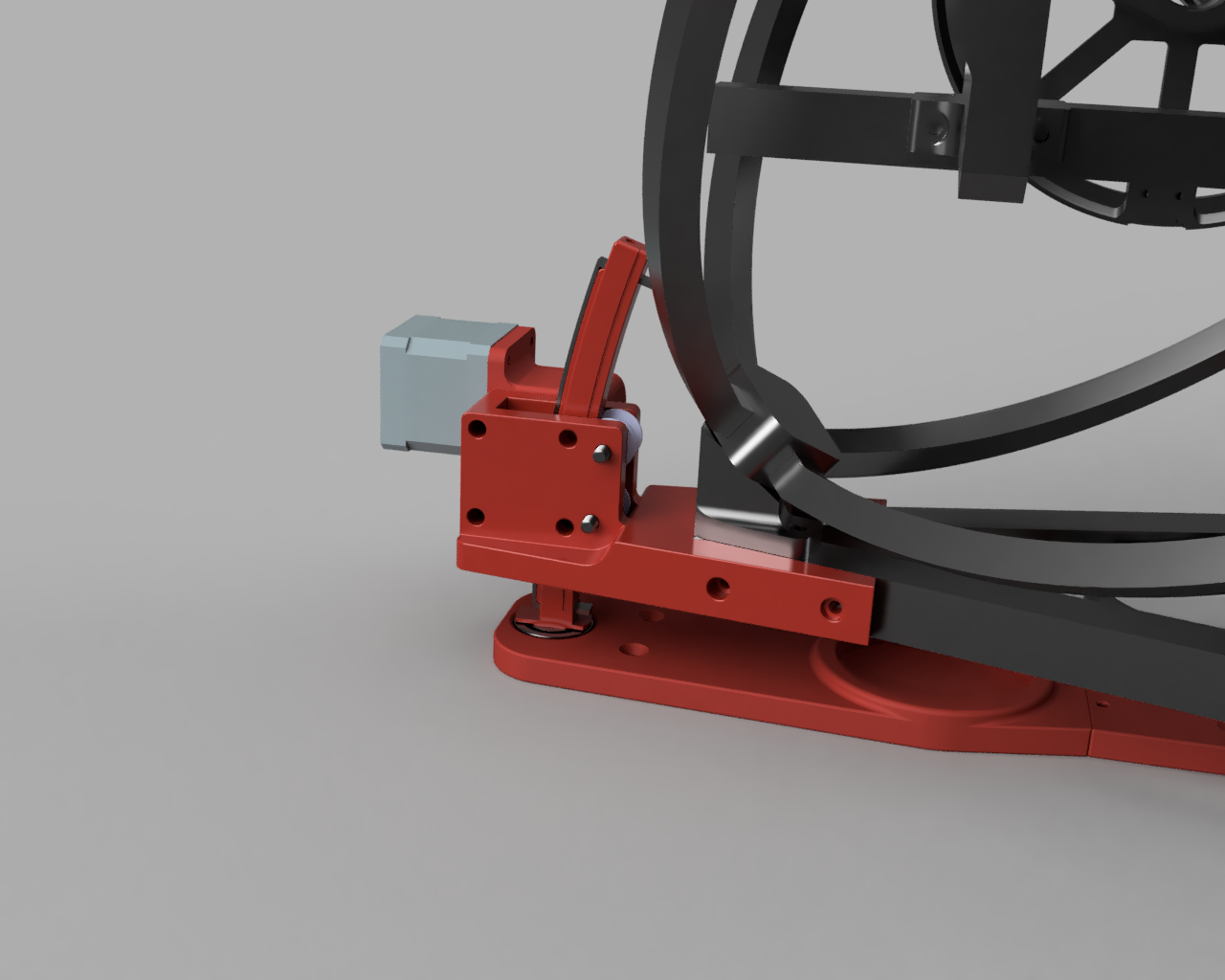
¶ Azimuth
- Assembly pivot frame using M3 screws and M3 nuts
- Insert 6001 bearing into pivot frame
- Assemble slide frame and motor mount using M3 screws.
- Attach slide frame and pivot frames together using M3 screws.
- Insert the bottom of the altitude track in the 6001 bearing on the pivot frame.
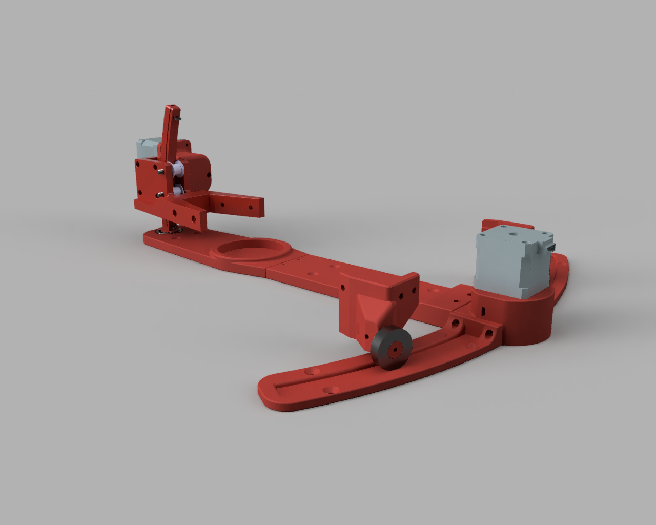
- Remove flange from 16T pulley. Install on Azimuth stepper.
- Install stepper on motor mount.
- Feed belt through motor mount.
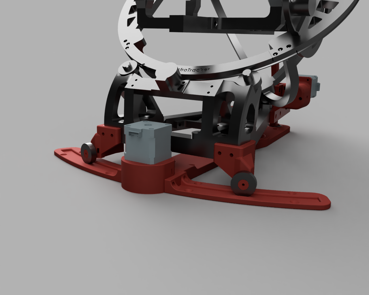
- Replace default left/right mounts with AutoPA parts.
- Install 6001 bearings on left and right mounts. Secure in place with u4_holder parts and M3 screws.
- Install M3 nuts/screws in left/right mounts for belt tightening.
- Feed the belt through left/right mounts with some slack on both ends.
- Install a GT2 belt tension spring as close as possible to the mounts.
- Tighten the belt screw on one of the front mounts. Pull the loose belt end while simultaneously pulling the motor block away from the tightened belt screw (both tension springs should be stretched at this point)
- Tighten the remaining belt screw.
¶ Assembly Finished
Once assembled the system can be tested. Ensure the firmware is up to date with 1.9.32 or later.
Use the minicontrol panel in OATcontrol to manually control each axis to test up/down/left/right.
¶ Wiring
Refer to Electronics for directions for which position to use on the control board for each stepper motor.
¶ Power Consumption
While OAT with the autoPA Addon might work using cheap boost converters connected to 5V USB Powerbanks, the additional power required by the addtional two motors might cause issues when exceeding the specs. Reported behaviour is that OAT restarts when Alt/Az Motors are moved.
¶ Software
The AutoPA system works with NINA TPPA or Sharpcap Pro to measure the aligment error and automatically adjust altitude/azimuth.
In NINA you will have to install the three point alignment plugin and activate logging in the settings.
If you use OATControl, no further software is needed. The standalone AutoPA script is available on Github.
¶ Installation and Usage
¶ Windows (without OATControl)
- Download AutoPA_v2.x.x.zip and extract.
- Run autopa_v2.x.x.exe
- Enter required settings if necessary. Do not start AutoPA yet.
- Open your polar alignment software (Sharpcap, NINA, etc) and start the polar alignment routine.
- Once a solution is shown for adjusting azimuth/altitude, start AutoPA and the mount will start adjusting automatically until aligned within the target accuracy.
You can use OATControl to check if everything is wired up and working correctly, under mini-control you can manually move Az/Alt. See OATControl Point 8/9.
¶ Linux
- Install prerequisites:
- sudo apt-get install python3-dev swig libindi-dev g++ libnova-dev libcfitsio-dev zlib1g-dev
- pip3 install pyindi-client
- Download autopa_v2.x.x.py and "indi. py" from source to the same folder.
- Run python3 ./autopa_v2.x.x.py
- Enter required settings if necessary. Do not start AutoPA yet.
- Open your polar alignment software (Ekos) and start the polar alignment routine.
- Once a solution is shown for adjusting azimuth/altitude, start AutoPA and the mount will start adjusting automatically until aligned within the target accuracy.
In addition to all of that please also check Software especially for Linux/Astroberry users check the sections Software > joystick_indi. You can use this script to manually move Az/Alt.