¶ Bottom mounted MKS Case
¶ Where to get the Parts
The bottom mounted MKS case is available for download from the GitHub OpenAstroTracker Addons repo.
Note: If you access and STL and it opens in your browser as some text file with a bunch of numbers, use the File > Save As command to save the STL.
¶ Required Hardware
- MKS Gen L
- Power wires, about 40cm, at least 20 AWG (0.5mm²) better 18 or 17 AWG (0.75 - 1mm²).
- Some M3 screws
- 5.1mm DC Jack, female
- 5.1mm power cable 12V (or a 12V wall adapter)
For the LCD (optional)
- See here.
Optionals
- Capacitor, between 10 and 25uF
- 8x M3x4.6x6mm Heatserts
The capacitor prevents the MKS from rebooting the very first time a program connects after the USB has been connected. However, it also prevents you from flashing new firmware.
So, to recap:
-
Without a capacitor
- The board resets when the first program connects after plugging in the USB cable. Subsequent connects don't cause resets.
- Firmware can be flashed at any time.
-
With the capacitor
- The board does not reset at all.
- Firmware can only be flashed after removing the capacitor. It needs to be re-inserted after flashing.
¶ MKS Case assembly
Cut 2 wires to approx. 20cm length each. Strip the isolation and open the terminals on the DC jack.
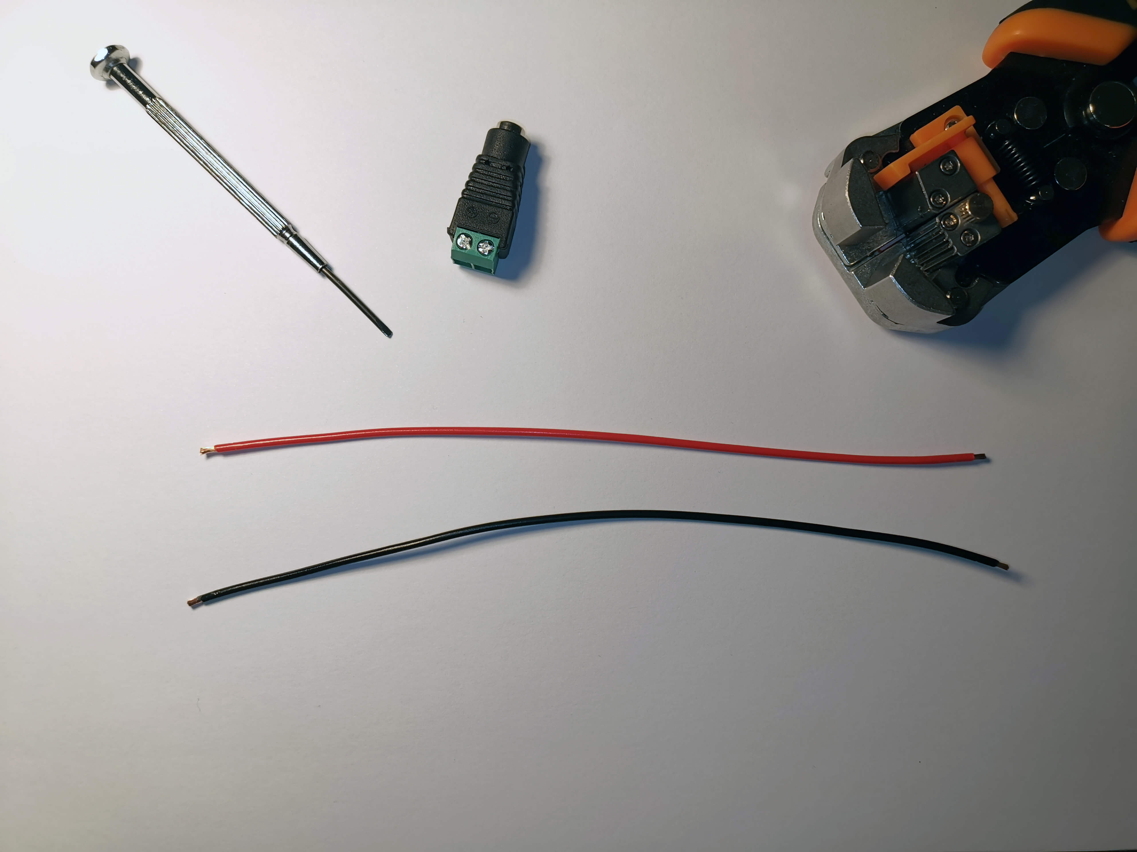
Insert the cables into the + and - port of the DC jack.
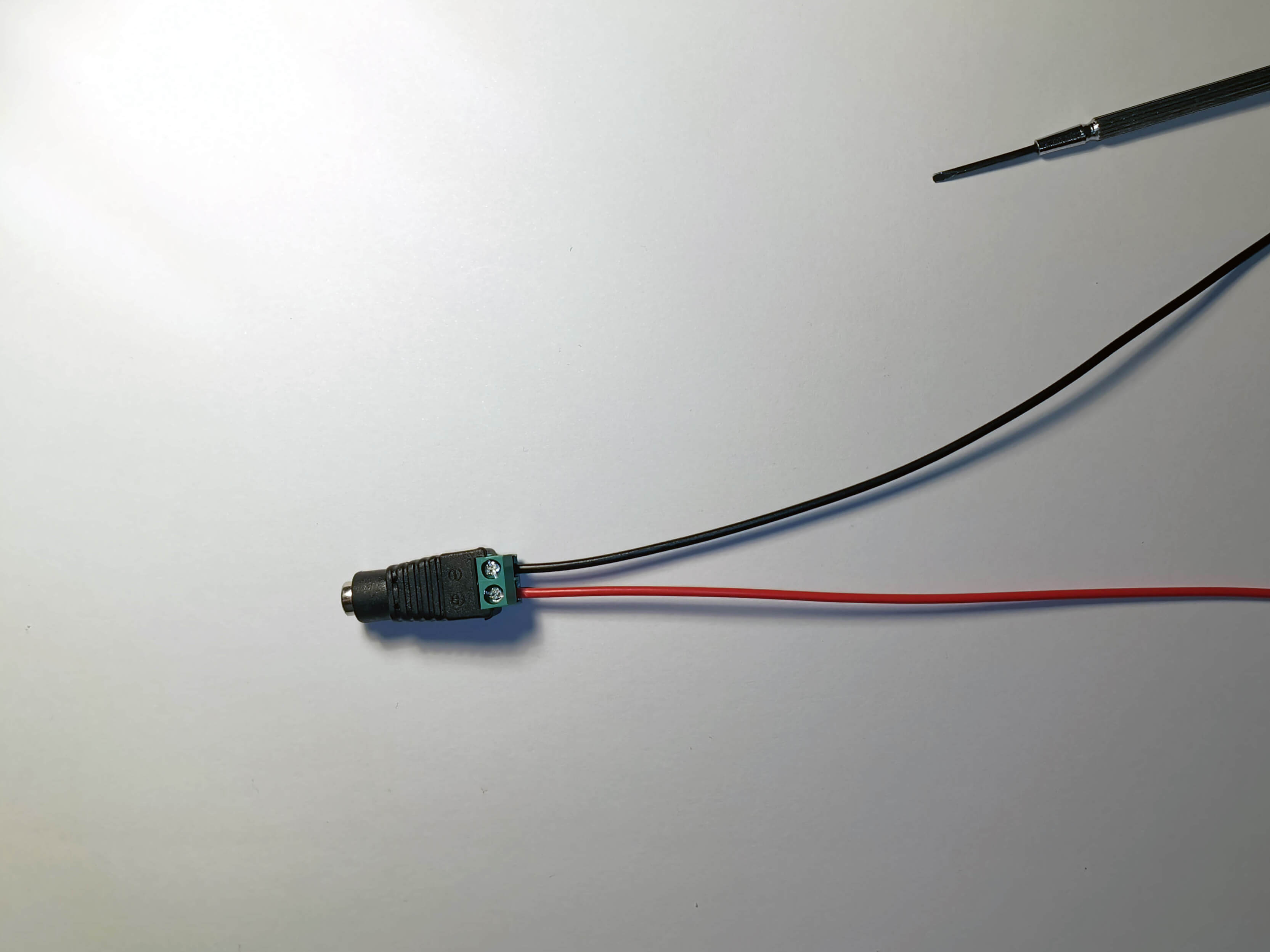
Push the DC jack into the side of the MKS case.
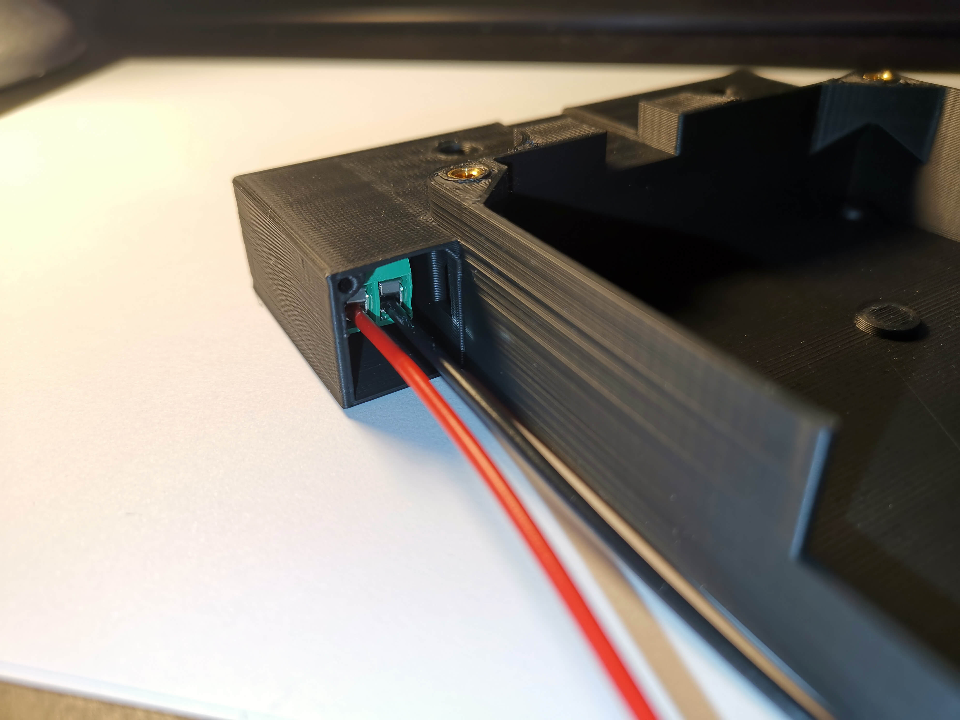
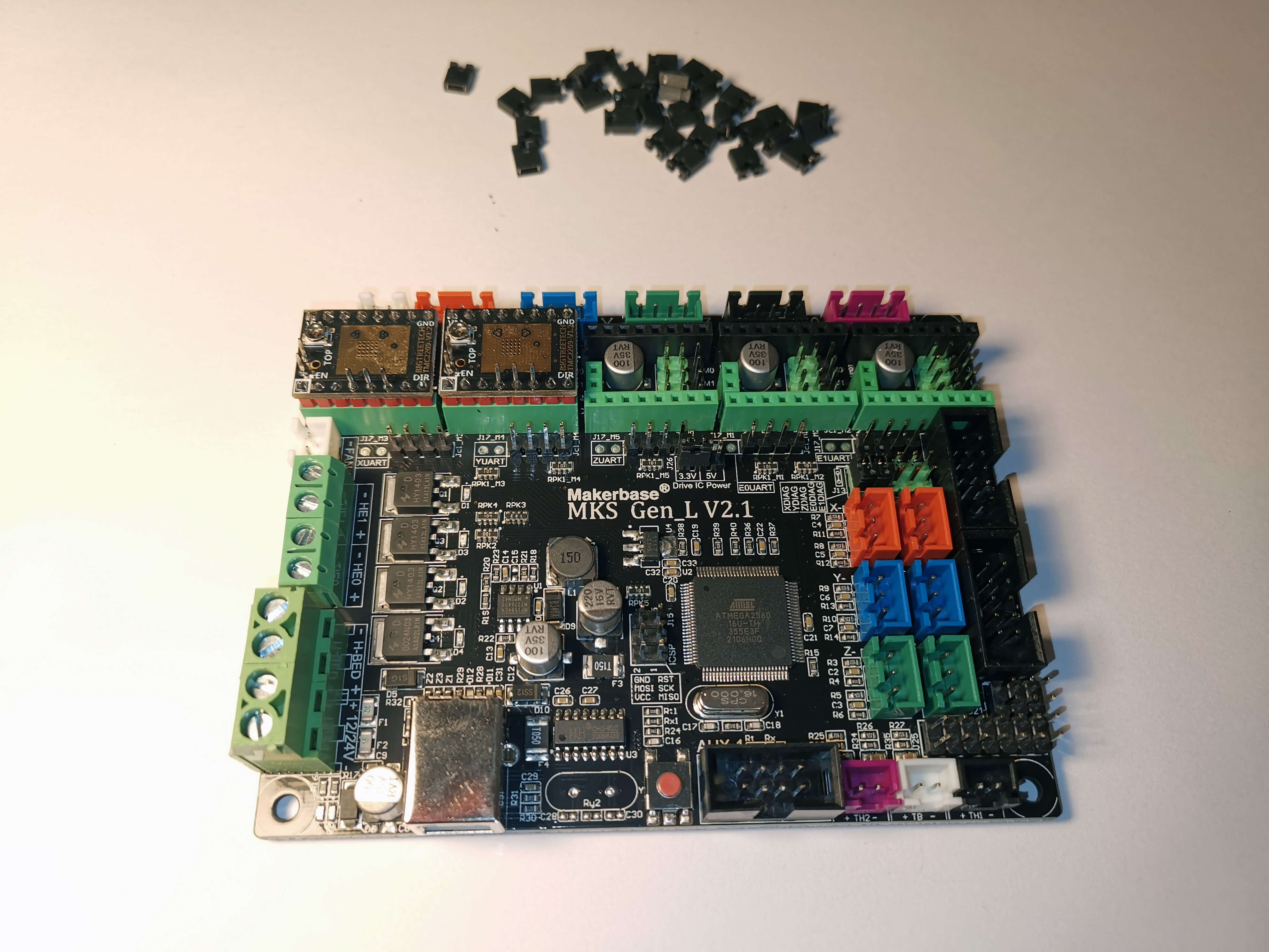
Place jumpers as shown for all drivers youre planning to use.
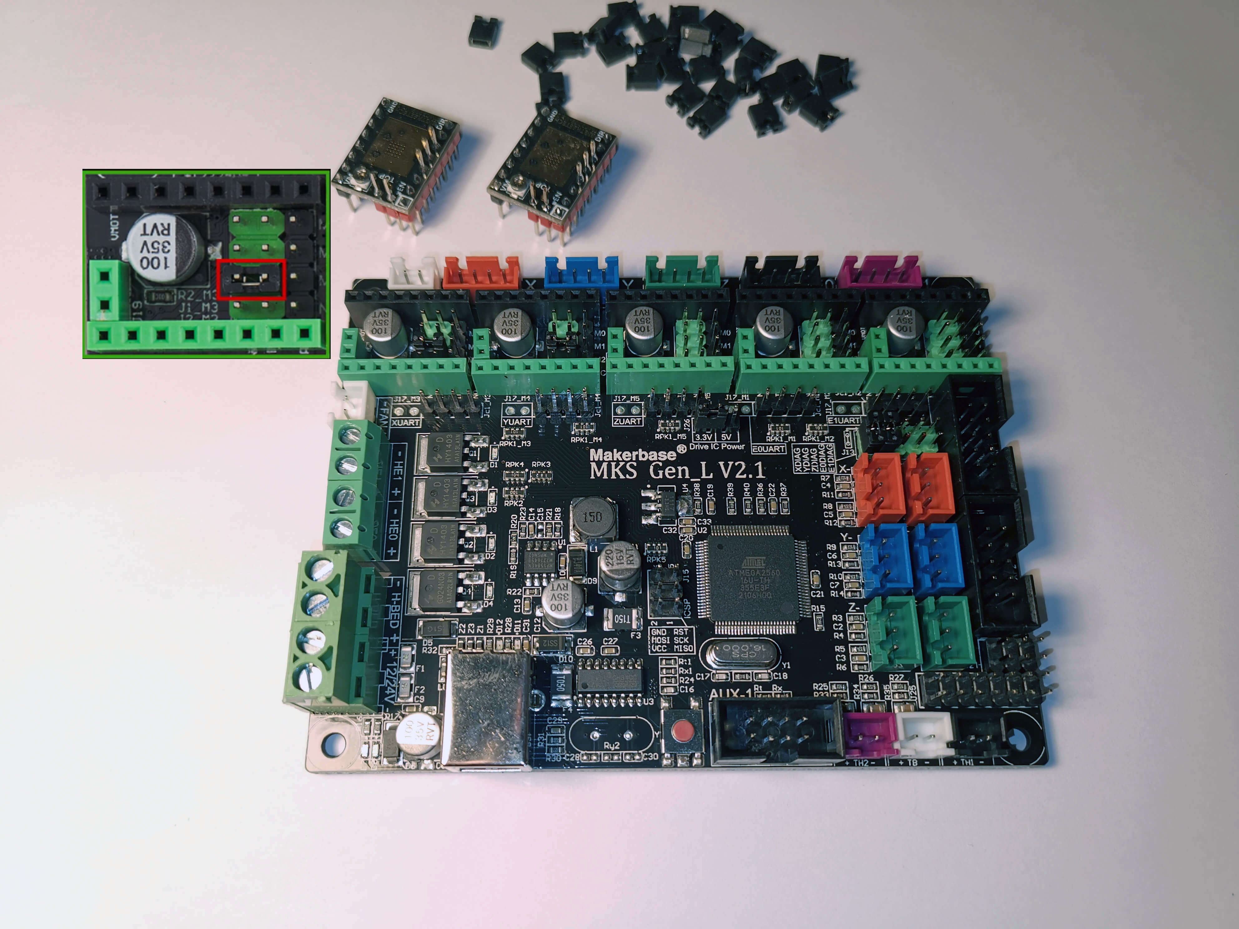
Place the drivers. Note the orientation.
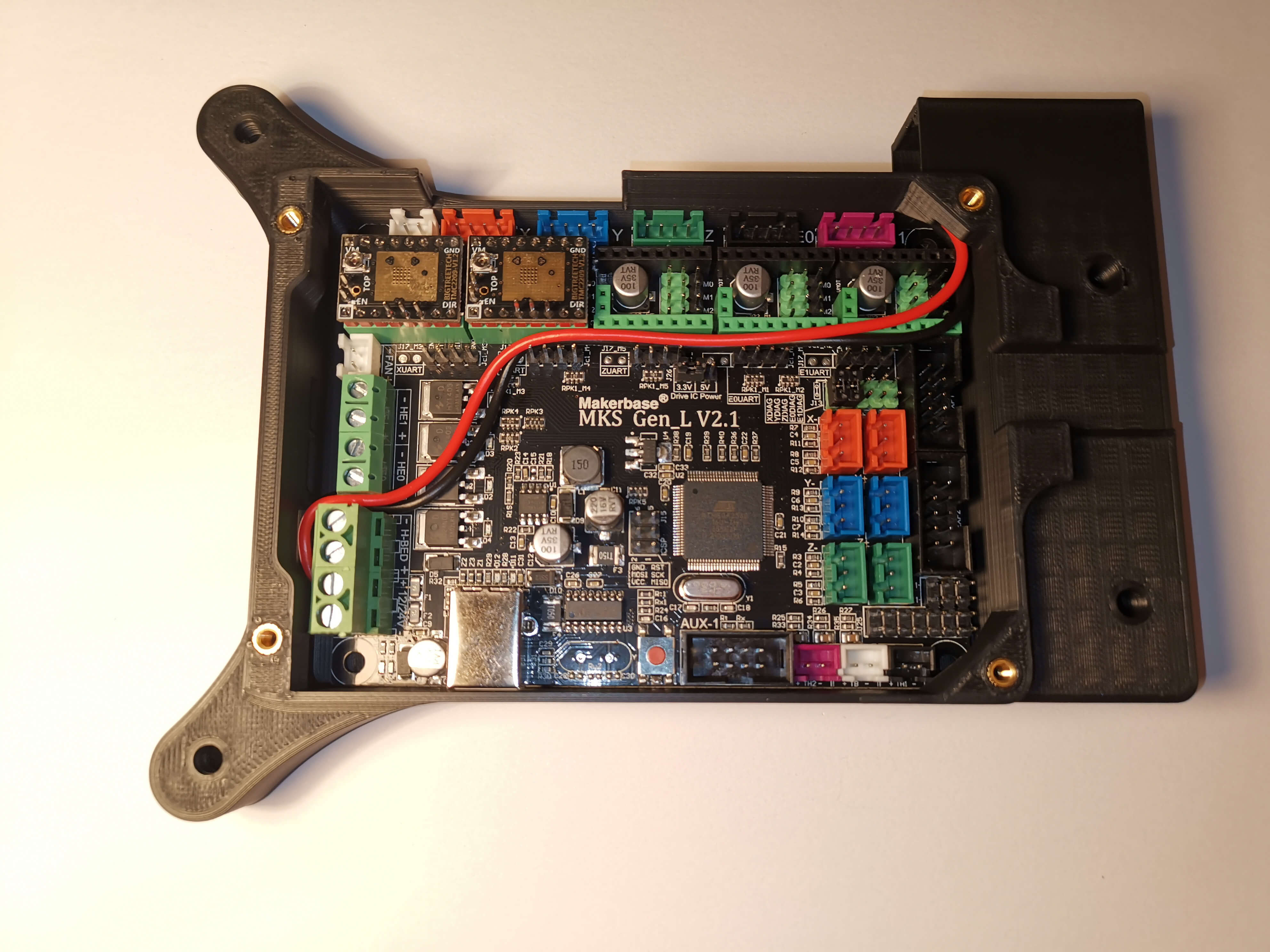
Place the MKS on the case. Route the two power wires through the small opening in the case. Route them over the MKS and insert them into the appropriate terminal.
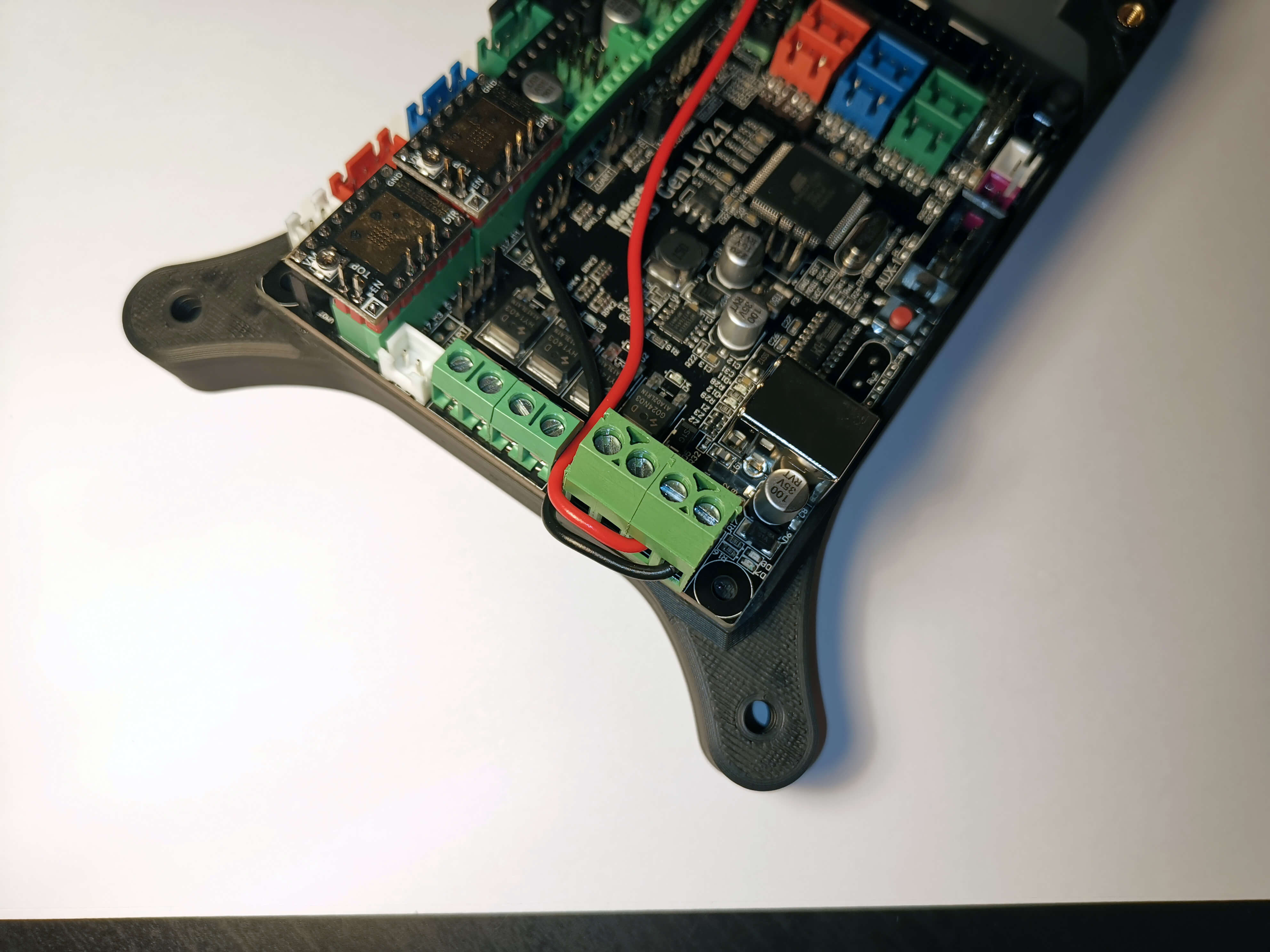
Slightly bend the power wires around the terminal. Push the MKS inside the case. This should only require gentle force.
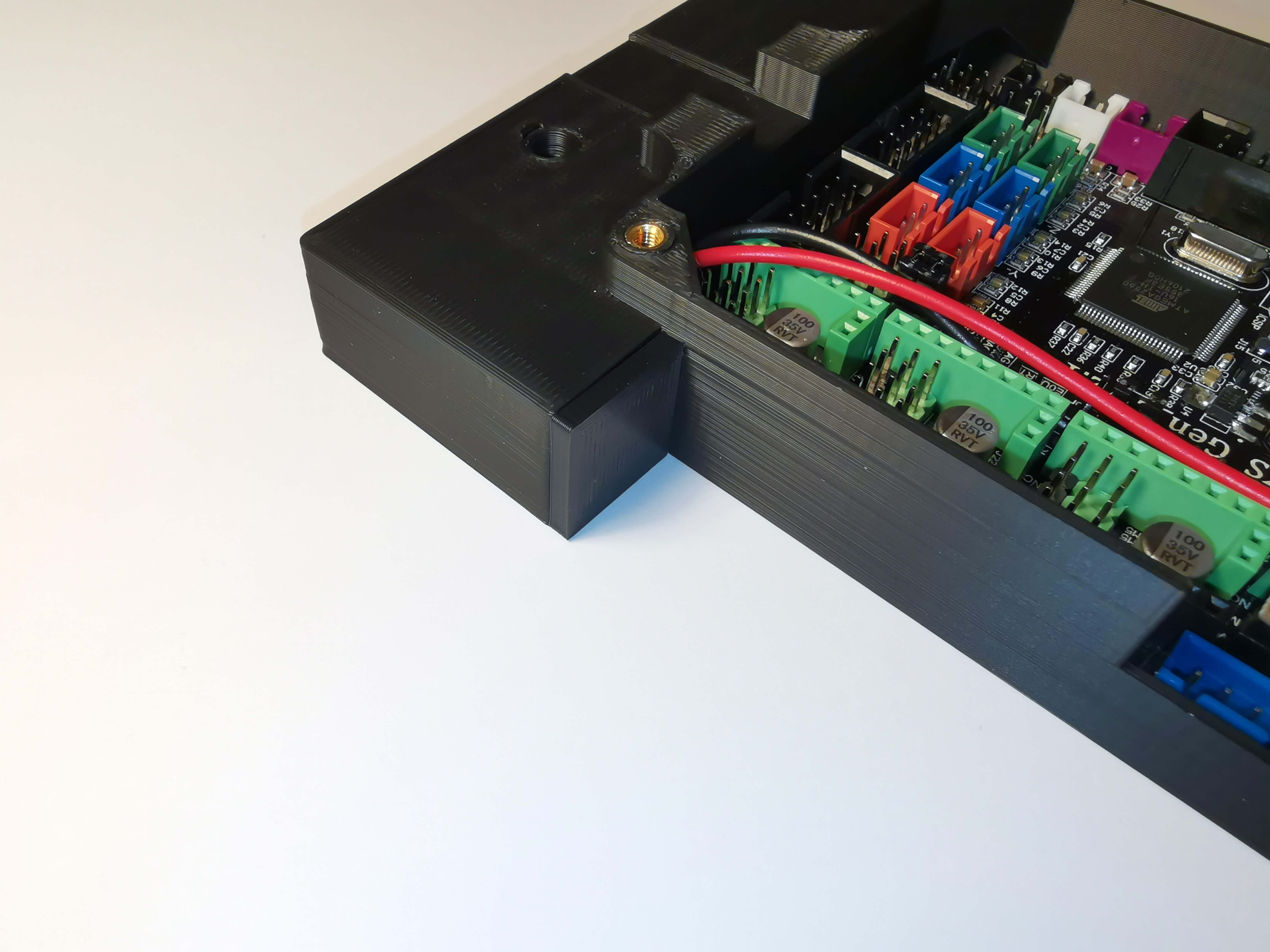
Plug the DC Lid as shown. If this doesnt hold well on its own, a drop of glue helps.
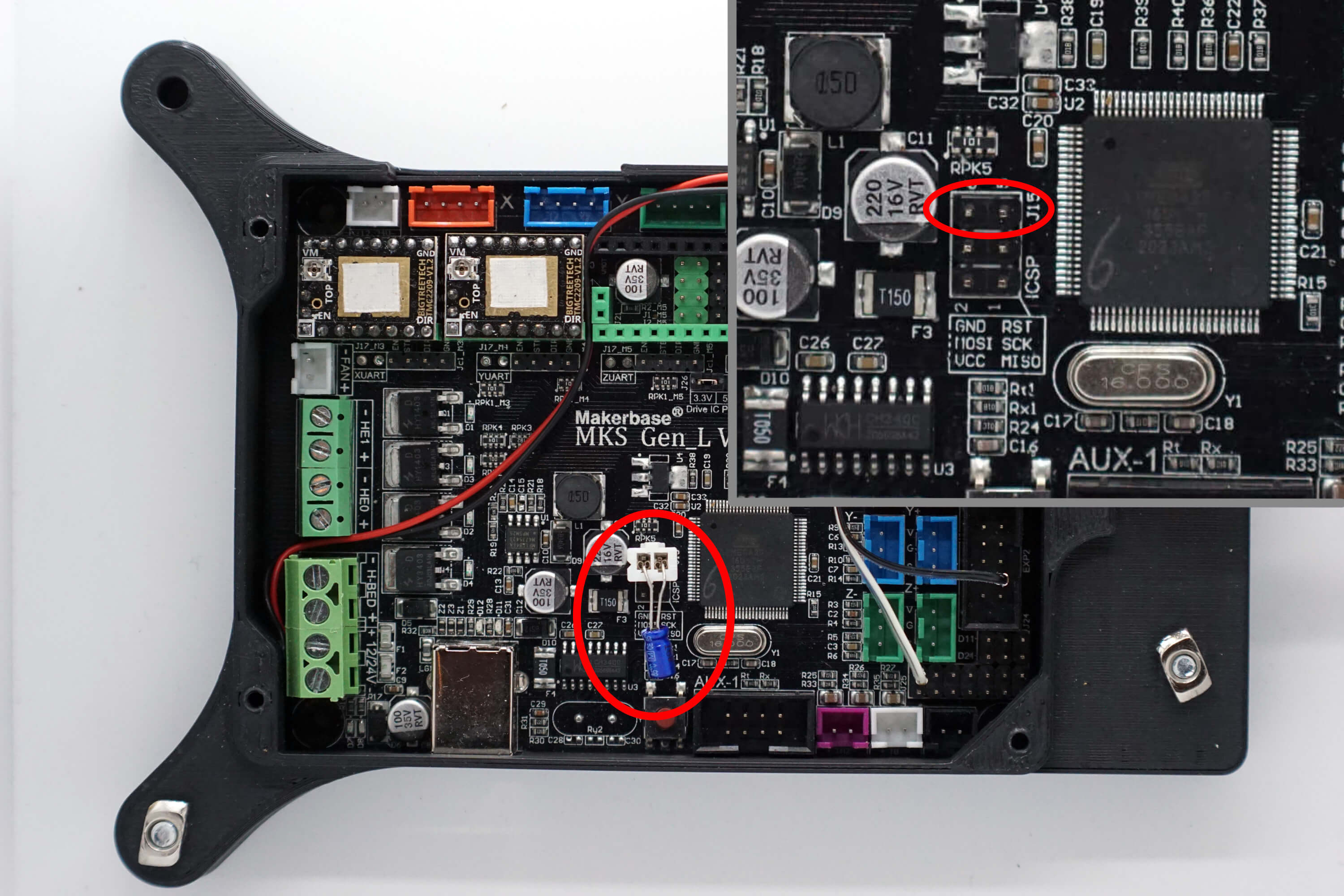
(Optional) Find a way to attach the capacitor to the MKS. A nice way is to crimp a JST-XH connector to it.

Place a capacitor (between 10 and 25uF) at the shown location, with the negative terminal of the capacitor on the left hand pin in the image - See the MKS Gen L v1.0 pinout here. Negative goes to GND and positive to RST.
¶ Display (Optional)
Refer to the LCD wiring page for details for connecting the LCD to the bottom mounted MKS.