¶ Included Parts
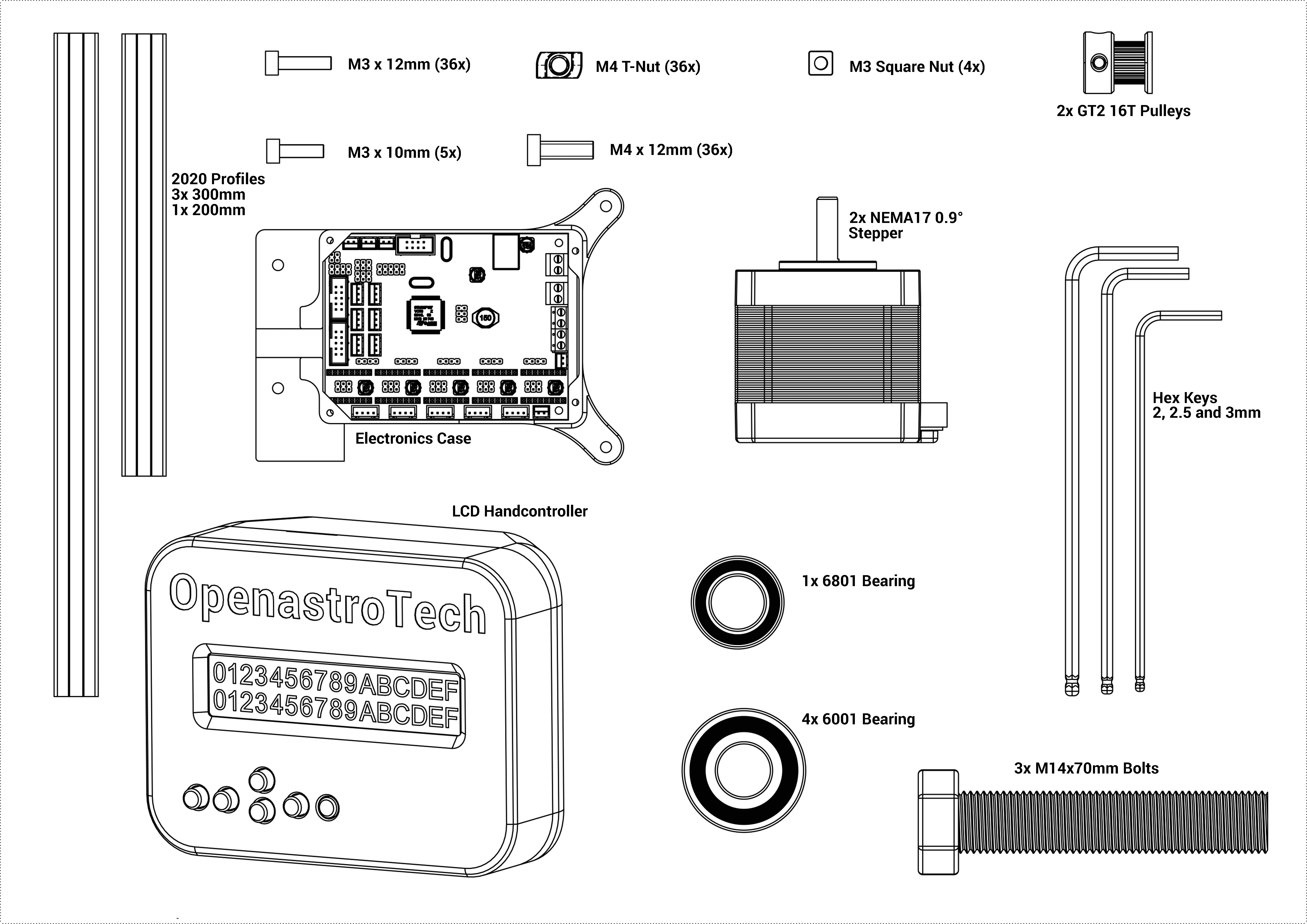
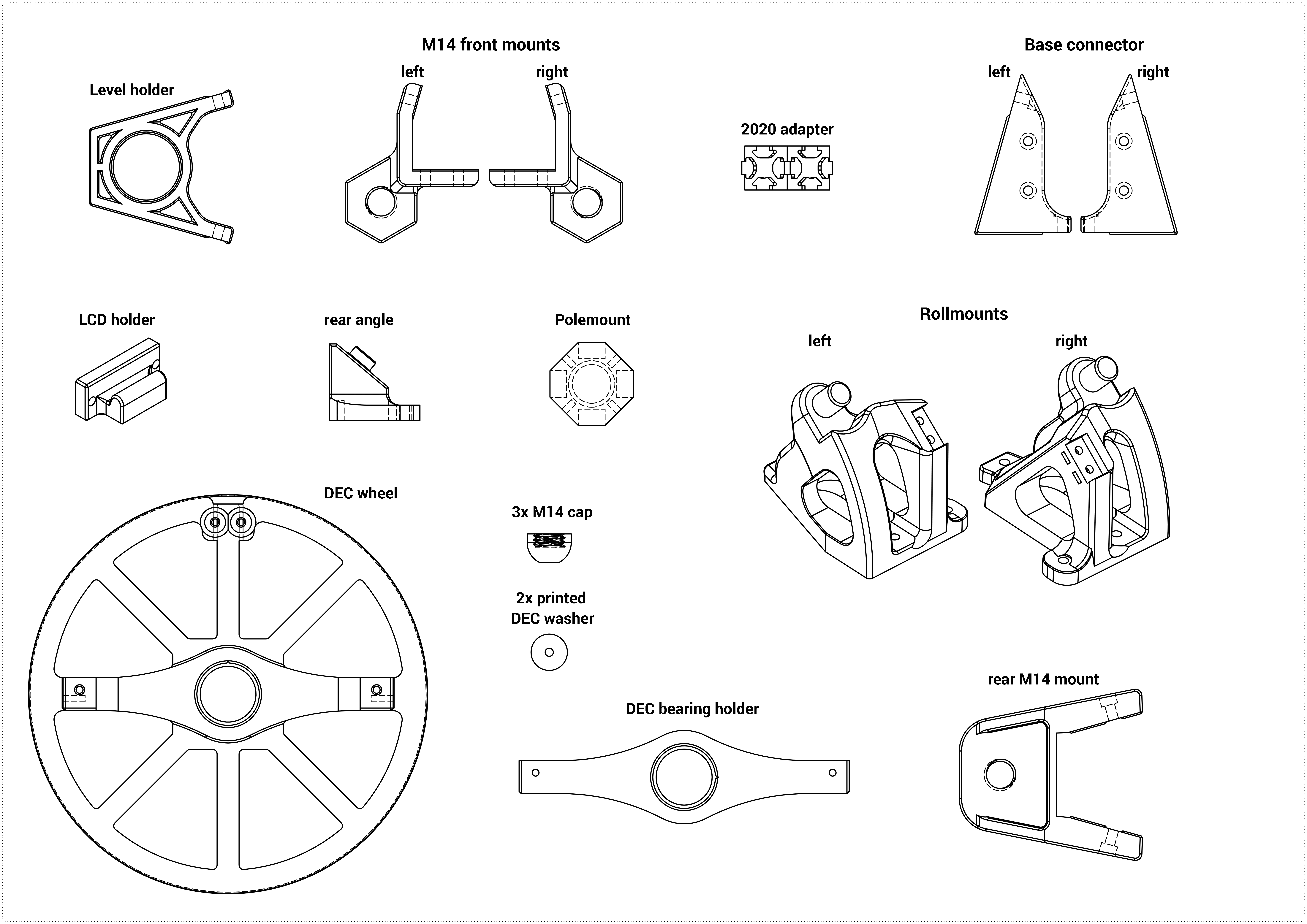
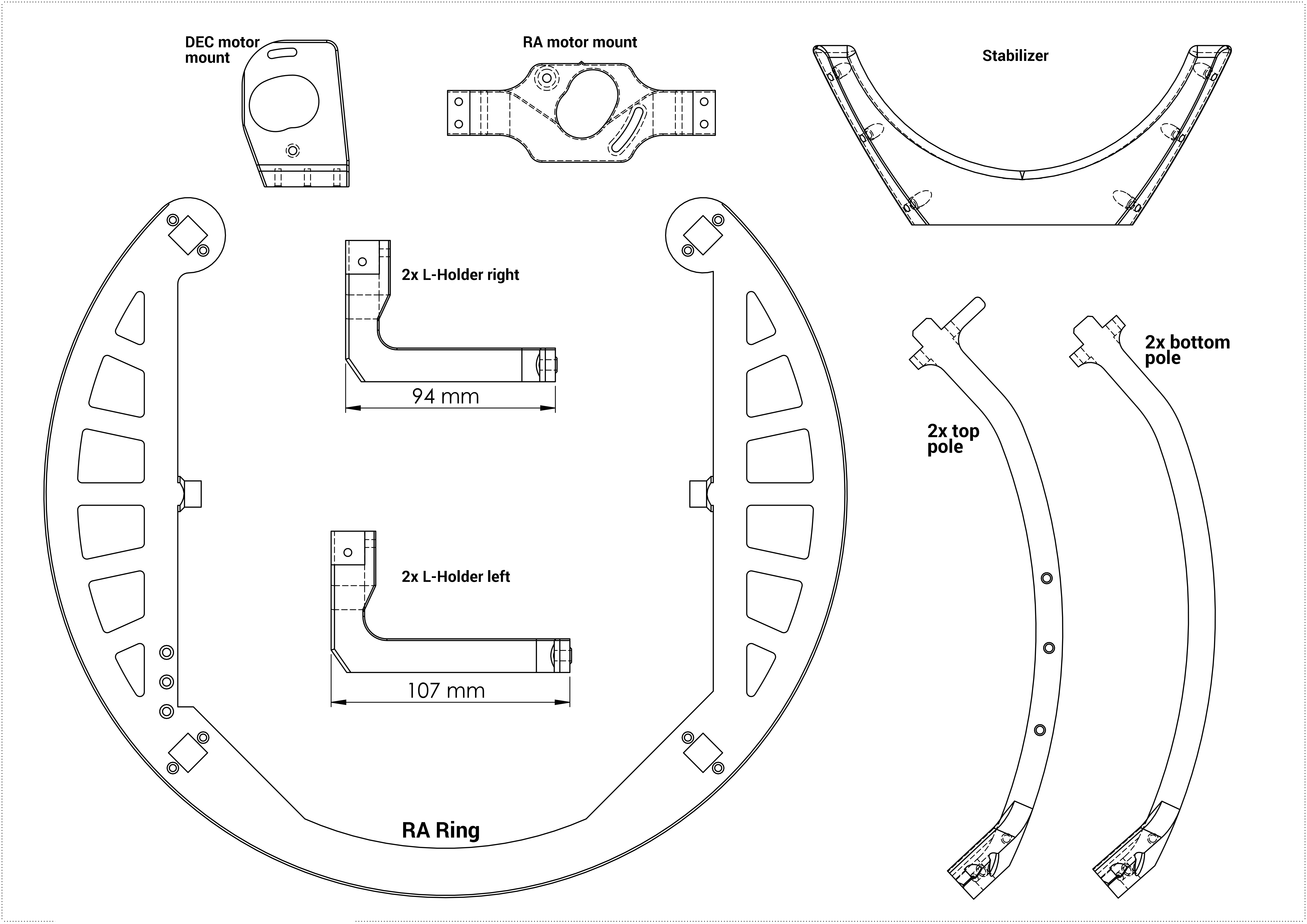
Also included are two GT2 belts in the correct length and a camera clamp. I could not get nice CAD drawings of these
¶ Assembly Part 1: Base
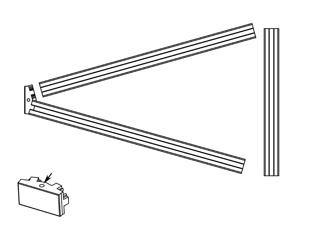
- Assembly
- Parts
- Push the two longer extrusions on the adapter. Note that the side with the smaller hole one the 2020 adapter will be the up side of the mount.
- 2 x 300mm aluminium extrusion
- 1 x 300mm aluminium extrusion
- 2020 adapter
- Assembly
- Parts
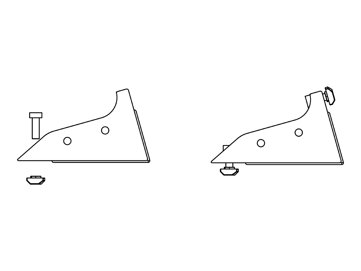
- Insert a M4 screw through the larger holes of a base connector. Then screw the T-Nut onto the screw, with the flat side facing the part as shown in the image. Don't tighten the screw though, leave it at the front of the screw.
- Base connector left & right
- 2x M4x12mm screws
- 2x M4 T-Nut
- Assembly
- Parts
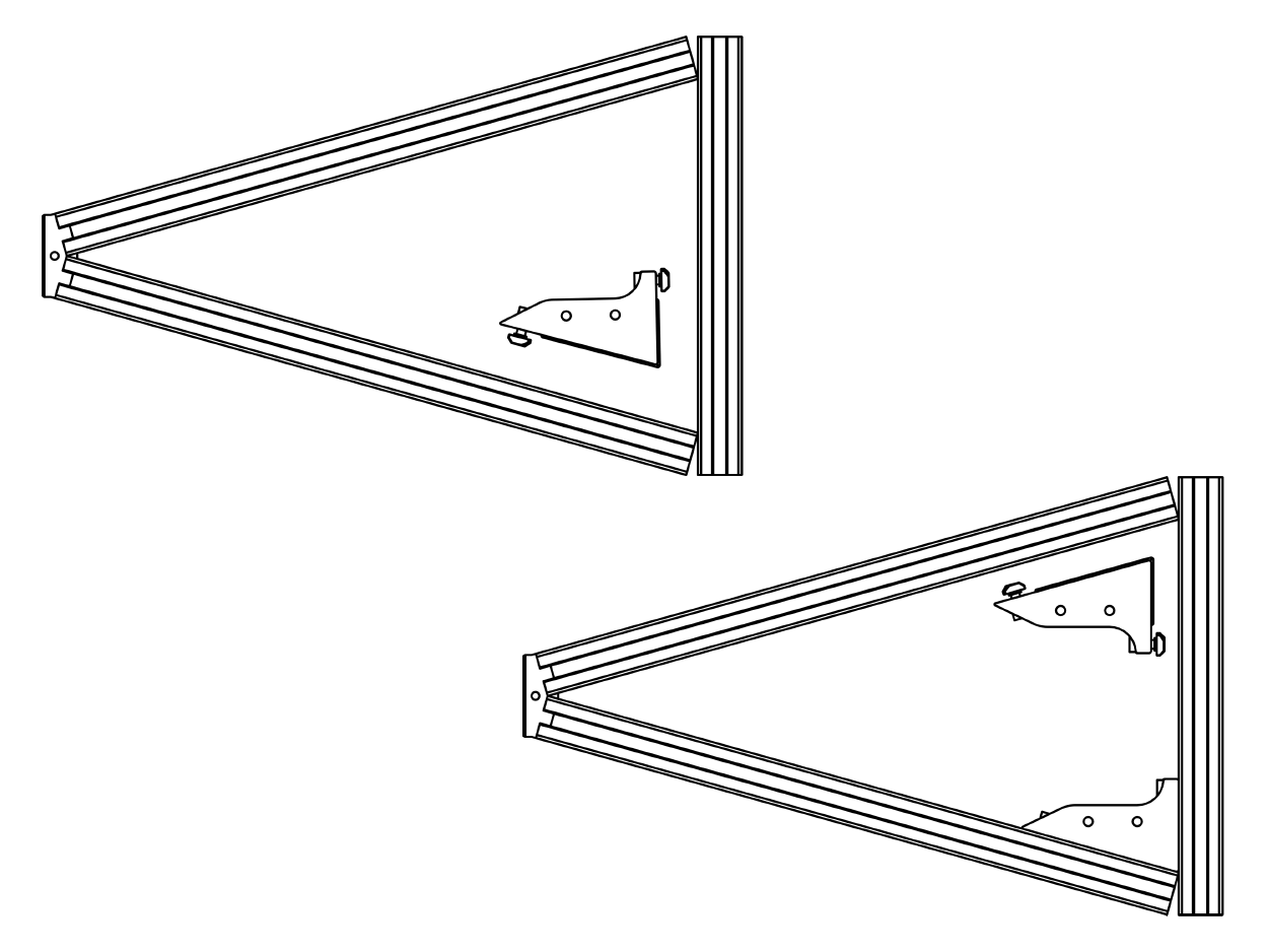
- Now take the shorter aluminum extrusion and lay it as shown. It should perfectly fit into the angle of the extrusions. Note that the connector part also has a side with a large and a small hole, the small hole should be on the same side as the "adapter" part from the first step.
- Don't fully tighten the screws just yet.
- 1 x 200mm aluminium extrusion
- Base connector from previous step
- Assembly
- Parts
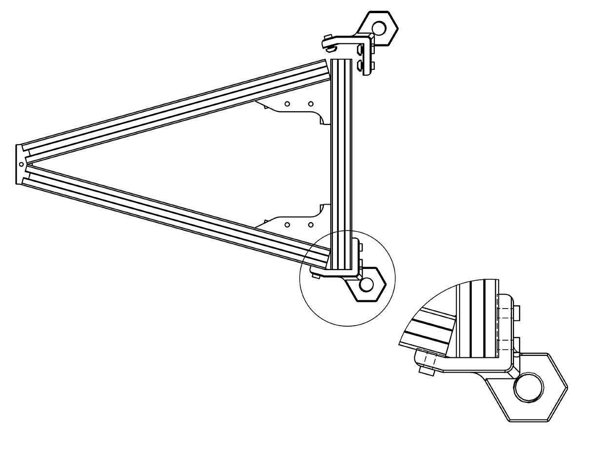
- Insert the 3 M4 screws and T-Nuts for each part just like the previous step, then lay the parts as shown.
- Make sure the aluminum profiles sit tight against the parts on all sides, then tighten the M4 screws.
- When the M14 mounts are properly tight and there are no gaps anywhere, also tighten the base connectors from the previous step.
- 2 x M14 front mount left & right
- 6x M4x12mm screws
- 6x M4 T-Nut
- Assembly
- Parts
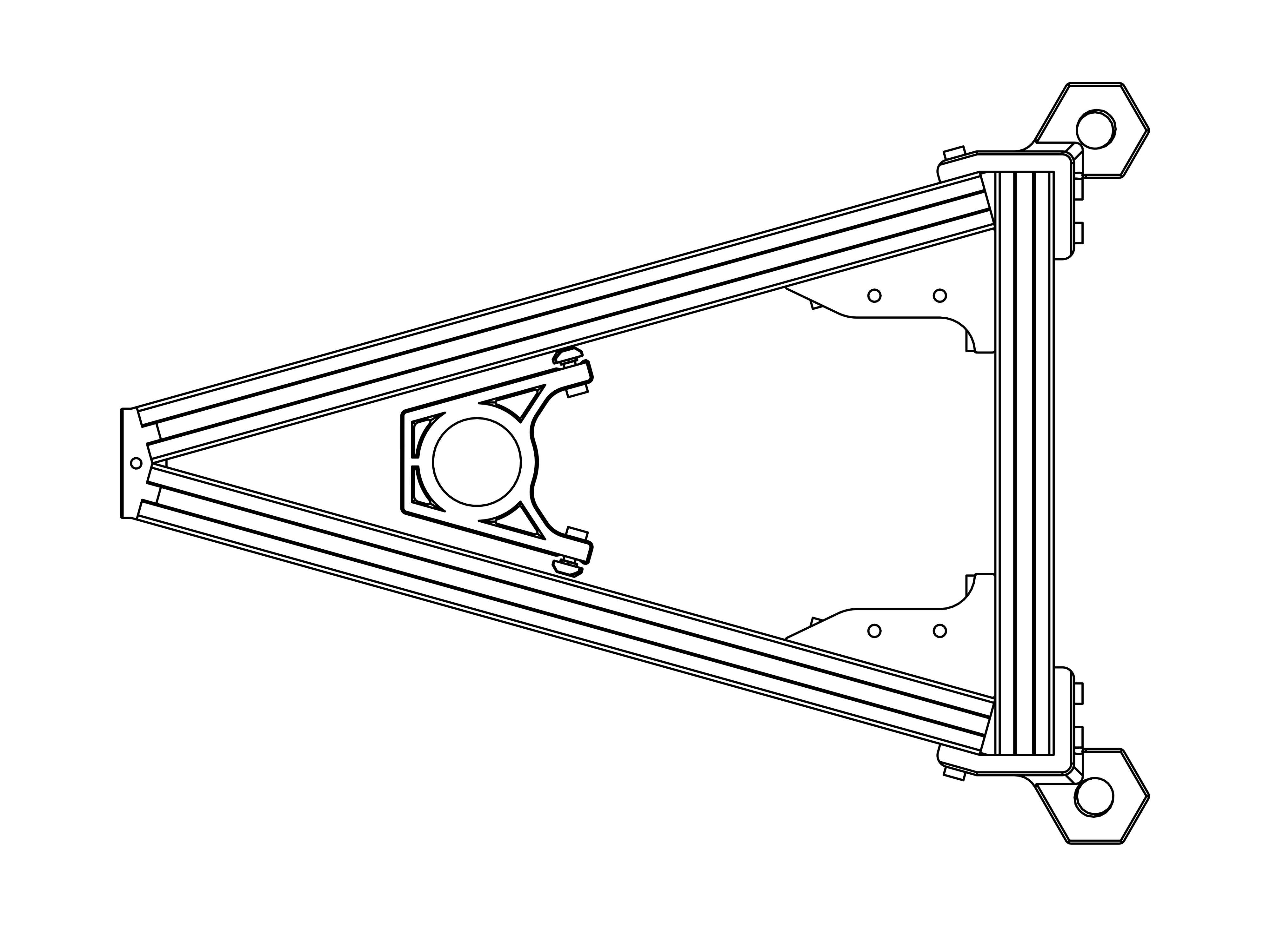
- Attach the M4 screws and T-Nuts the usual way.
- Slide the level holder in from the front as shown, then tighten the screws.
- Level holder
- 2x M4x12mm screw
- 2x T-Nut
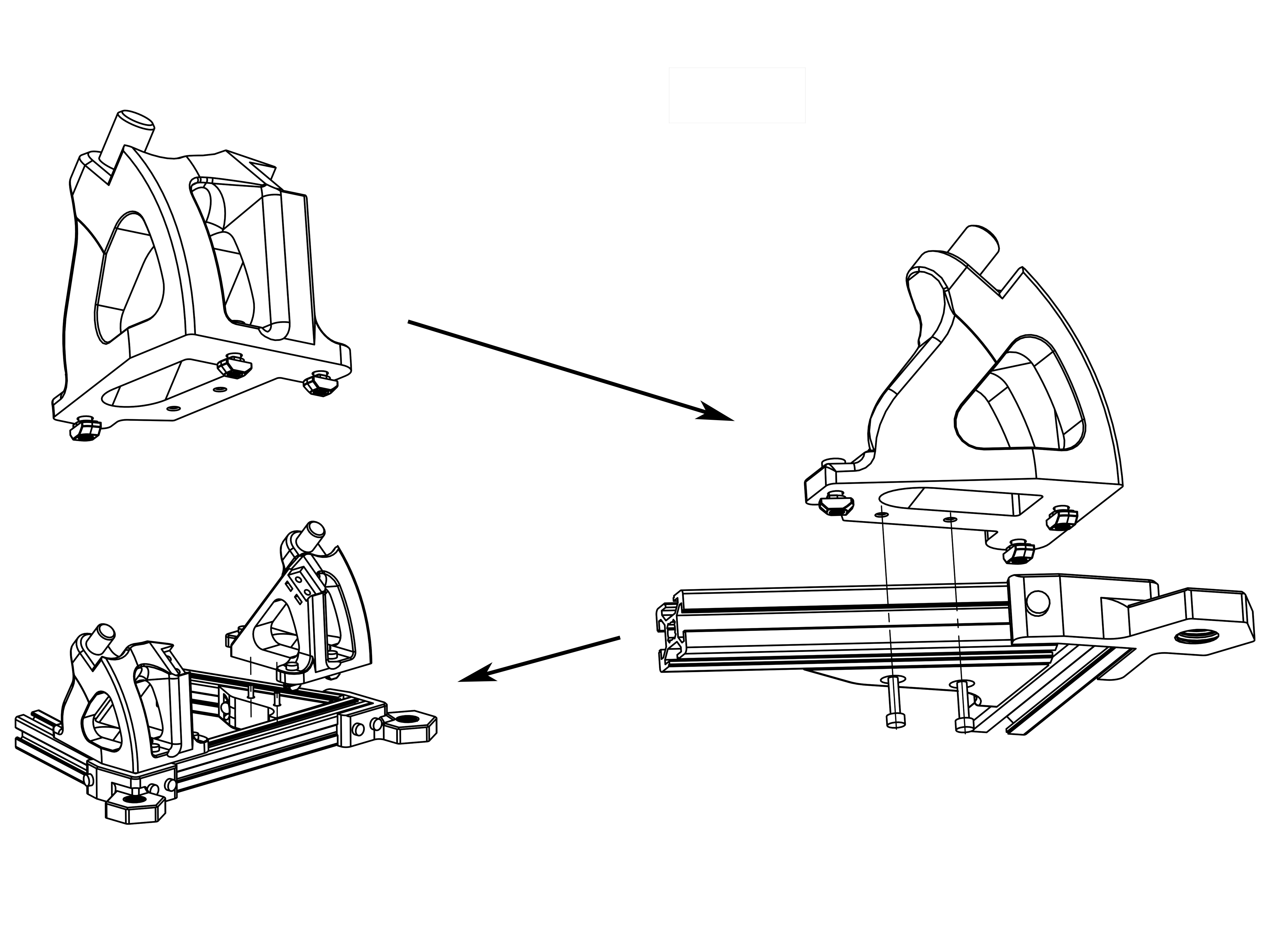
- Assembly
- Parts
- Take one of the Rollmounts and attach 3 M4 Screws and T-Nuts to it.
- Put it on the assembly as shown, then before tightening the M4 screws, take 2 M3x12mm screws and insert them from the bottom of the base connectors and screw them tight. Only then tighten the M4 screws. This ensures perfect alignment of the part.
- Repeat for the other Rollmount.
- 2 x Rollmount left & right
- 6x M4x12 & T-Nut
- 4x M3x12mm Screws
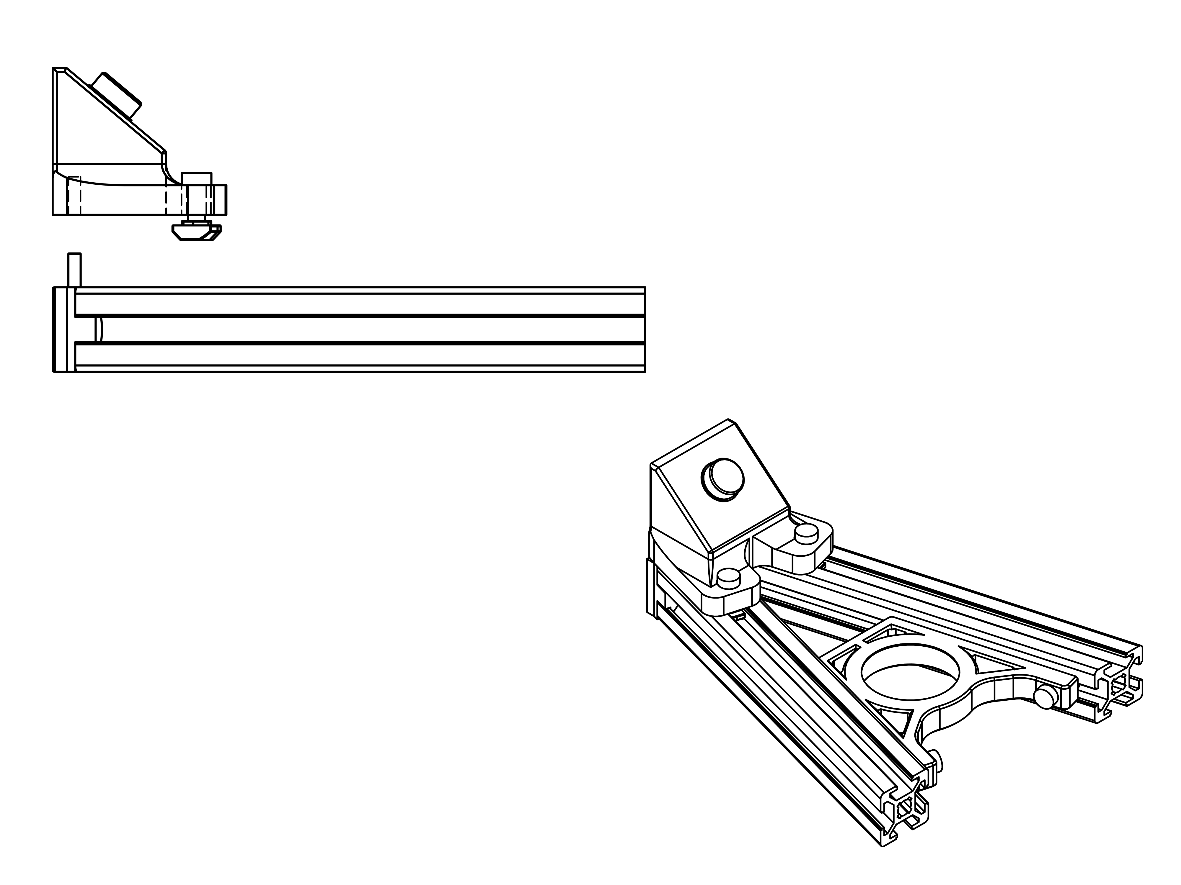
- Assembly
- Parts
- Attach the 2 M4 screws and T-Nuts to the angle part.
- Just like in the previous step, first screw in the M3x12mm screw from the bottom, then tighten the M4 screws
- 1x rear angle
- 2x M4x12 & T-Nut
- 1x M3x12mm Screw
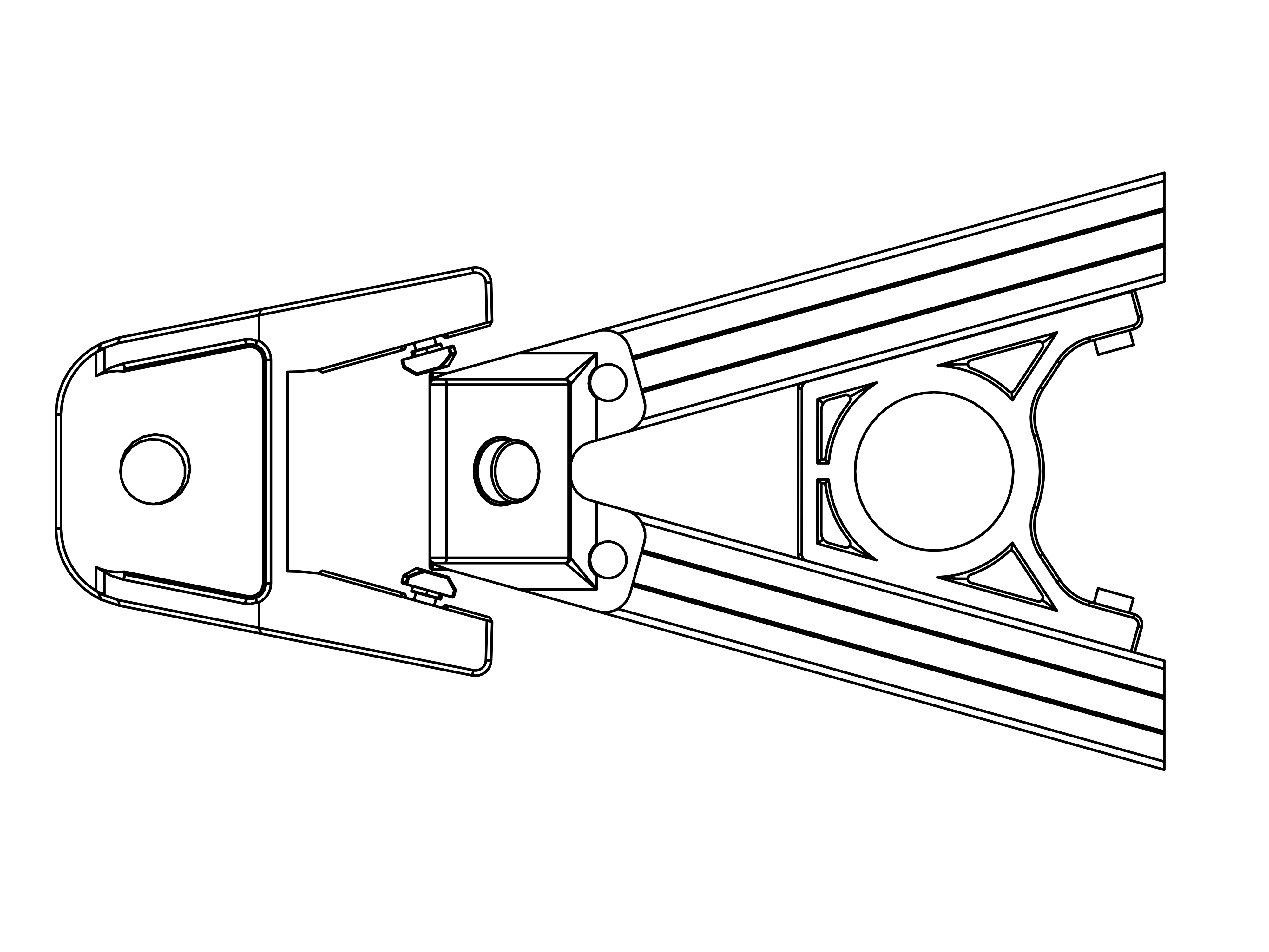
- Assembly
- Parts
- Insert the M4 screws and T-Nuts as shown.
- Push the part in from the rear side, so that the T-Nuts go into the slots of the alu rail. With slight force, the part will click into position.
- Tighten the M4 screws.
- 1x rear M14 mount
- 2x M4x12 & T-Nuts
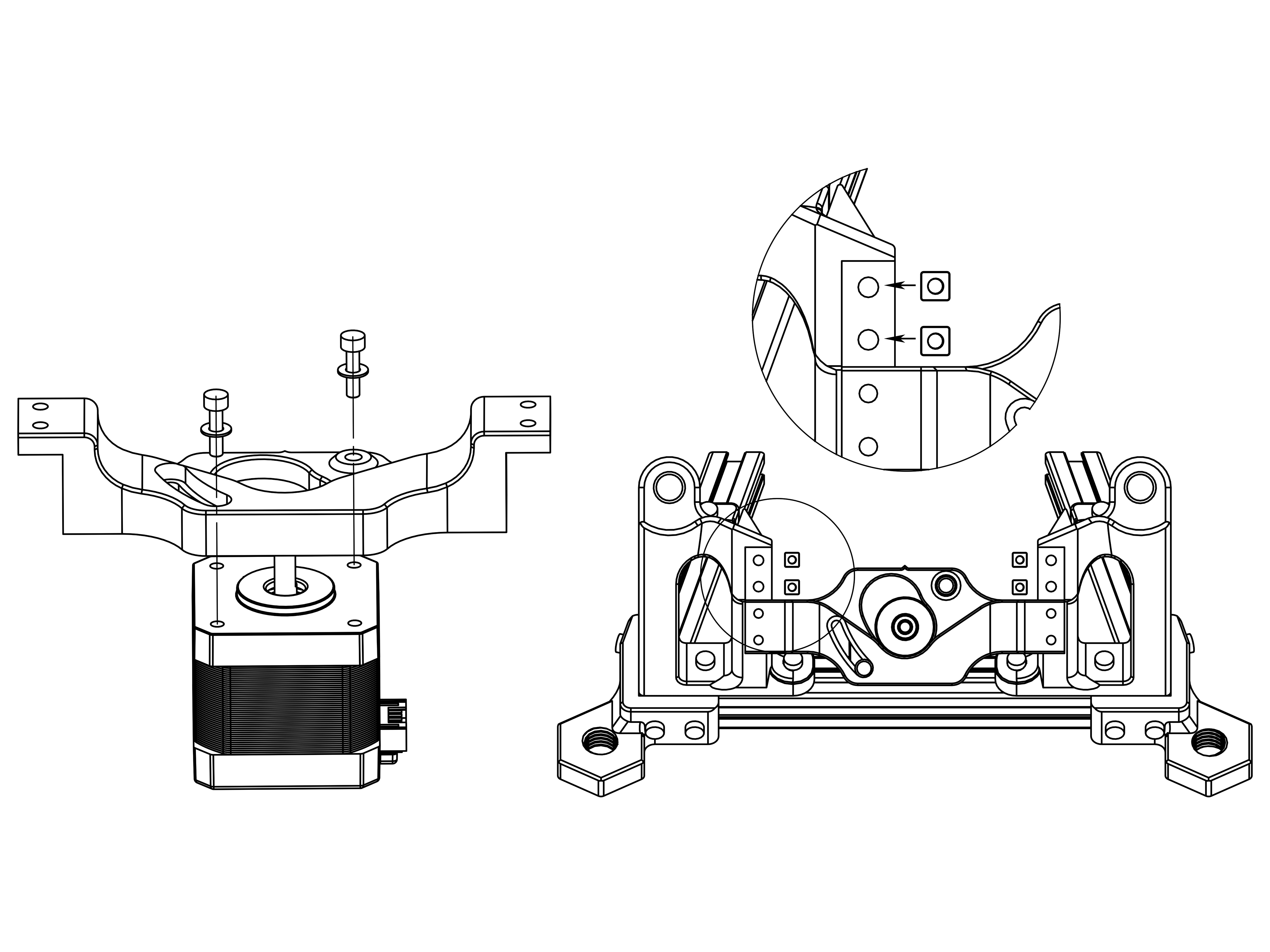
- Assembly
- Parts
- Attach the RA stepper (the one with short cables) to the RA motor mount with 2 M3x12mm screws and M3 washers as shown. Make sure the wires go out of the right side, the orientation should be exactly as in the picture.
- Push the RA motor mount onto the Rollmounts. Make sure the little indicator on it is facing up. (In the image there are 4 square nuts, these have since been replaced by inserts)
- Use 4 M3x12mm screws and screw the motor mount to the Rollmounts.
- The long slot on the motor mount is later used to tighten the belt, leave it loose for now so the motor can slide up and down.
- 1x RA motor (short wire)
- 1x RA motor mount
- 2x M3x12mm & M3 washers
- 4x M3x12mm screws
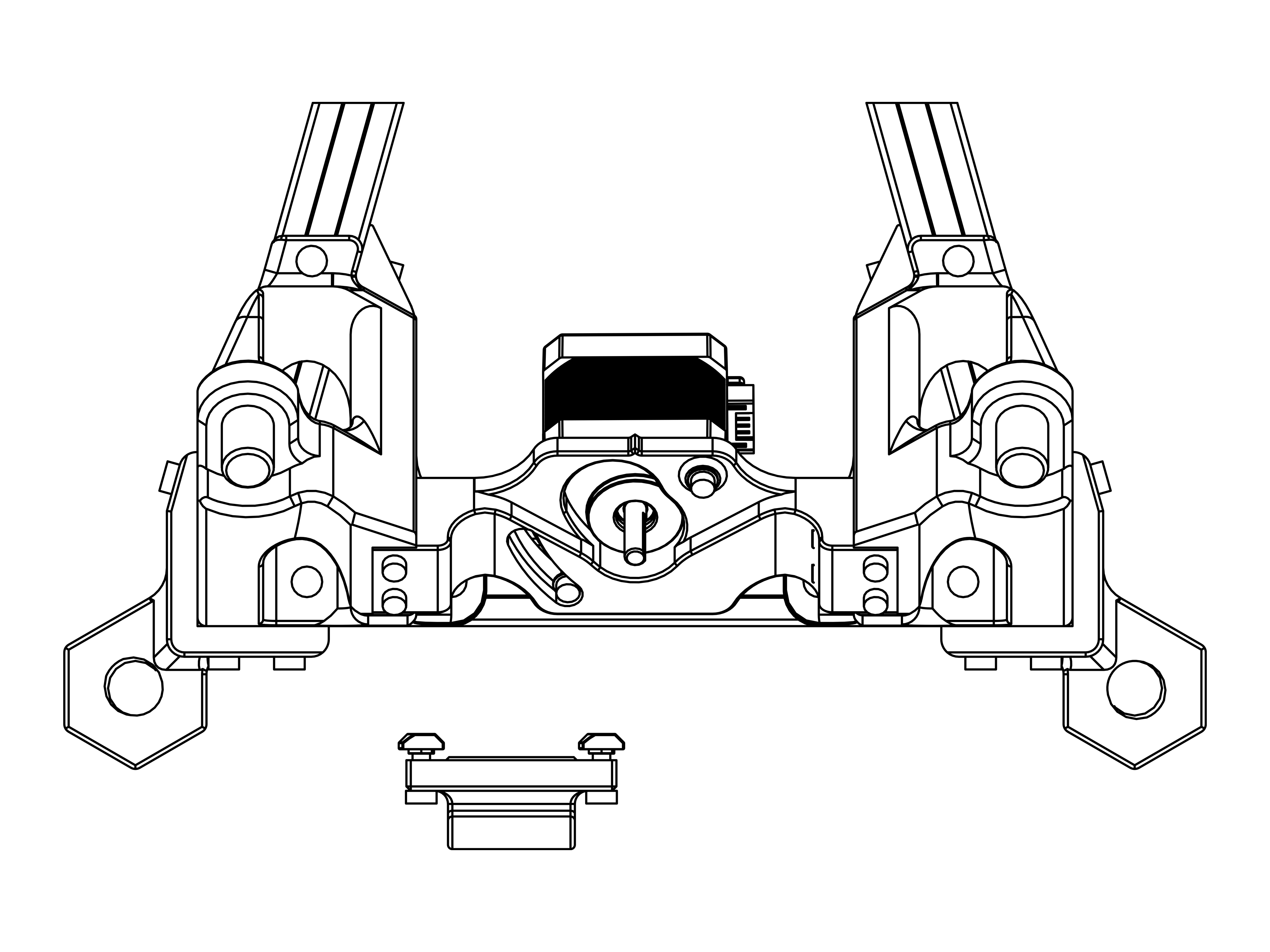
- Assembly
- Parts
- Insert M4 & T-Nuts into the LCD holder.
- Attach it to the front of the base as shown.
- 1x LCD holder
- 2x M4x12 & T-Nuts
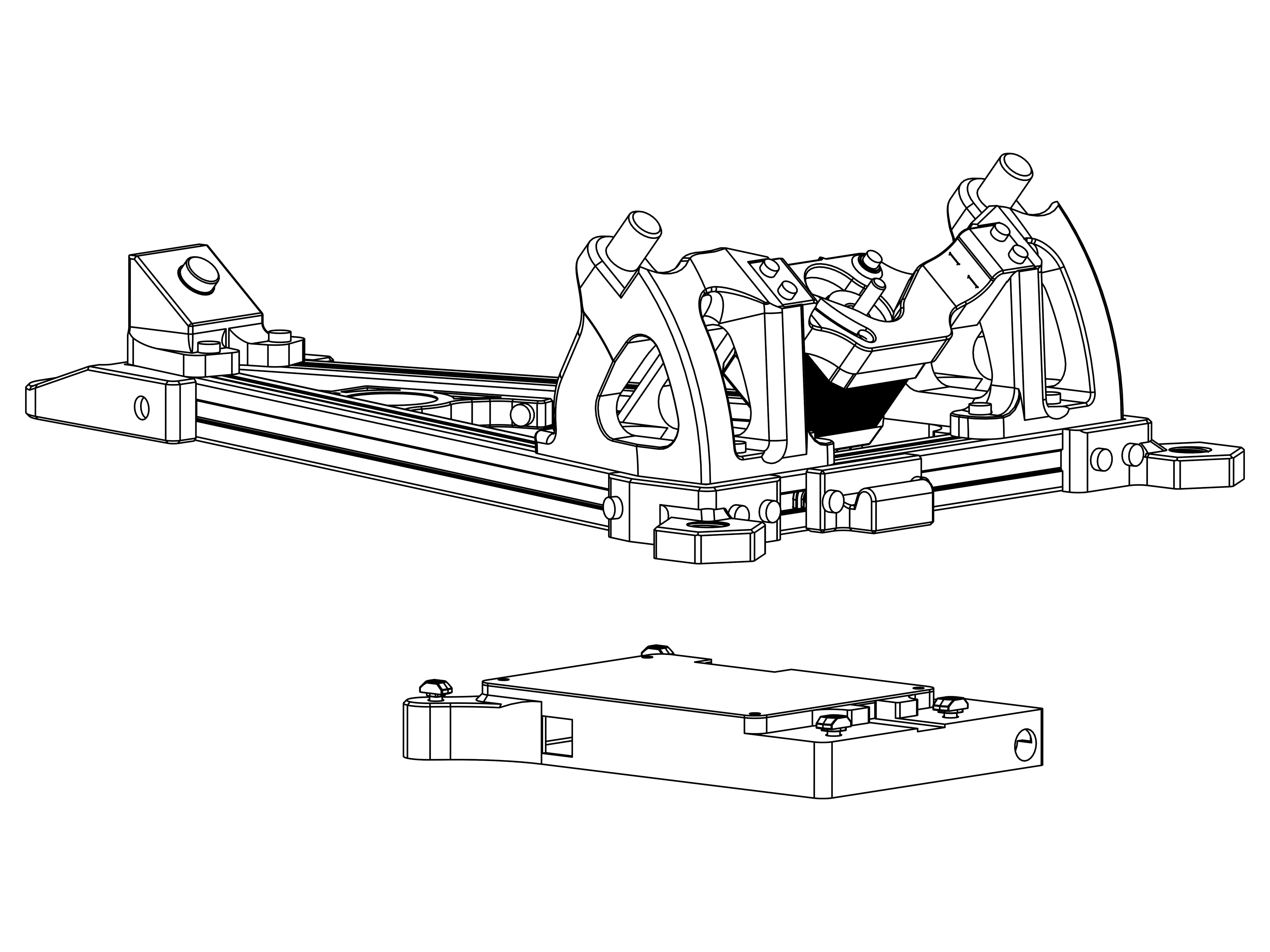
- Assembly
- Parts
- Insert M4 & T-Nuts into the Case
- Attach the Case to the base as shown.
- 1x Electronics Case
- 4x M4x12 & T-Nuts
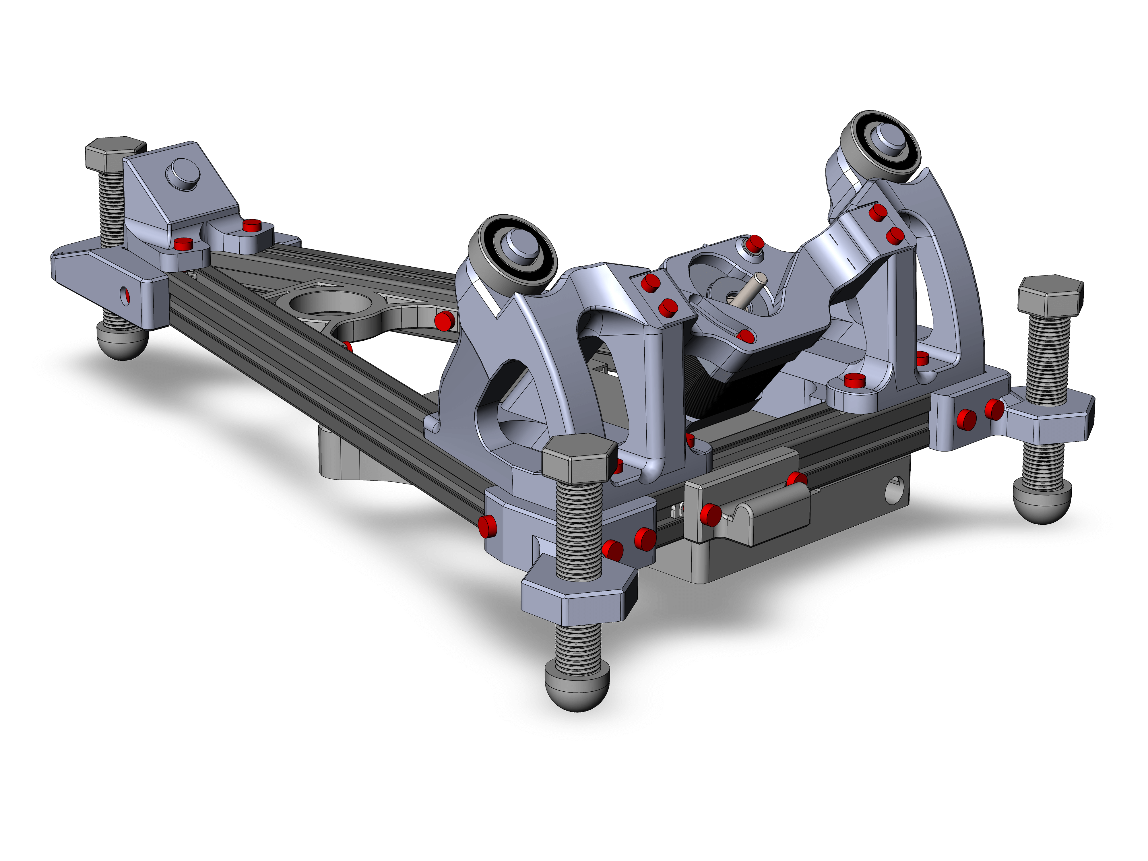
- Assembly
- Parts
- Your base should look like this now.
- Take the 3 M14 bolts and screw them into the 3 M14 holders. Attach the M14 caps to their bottom.
- Push the 2 6001 bearings onto the Rollmounts as shown.
Be careful when pushing the 6001 bearings on the rollmounts to not break them accidentally.
- 3x M14 bolts
- 3x M14 cap
- 2x 6001 bearing
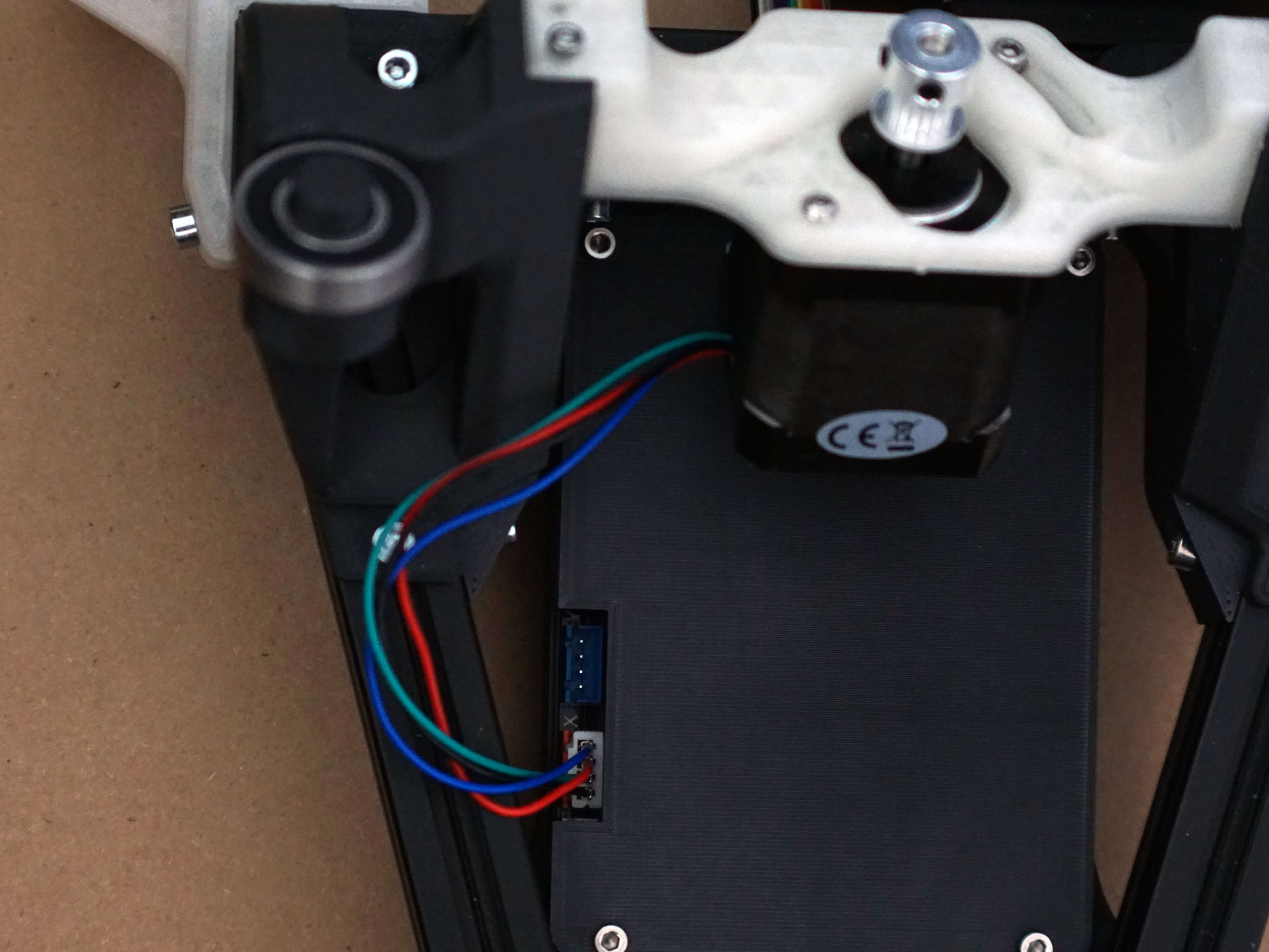
- Assembly
- Parts
- Take the cable from the RA motor and push it into the red connector.
¶ Assembly Part 2: Ring
- Assembly
- Parts
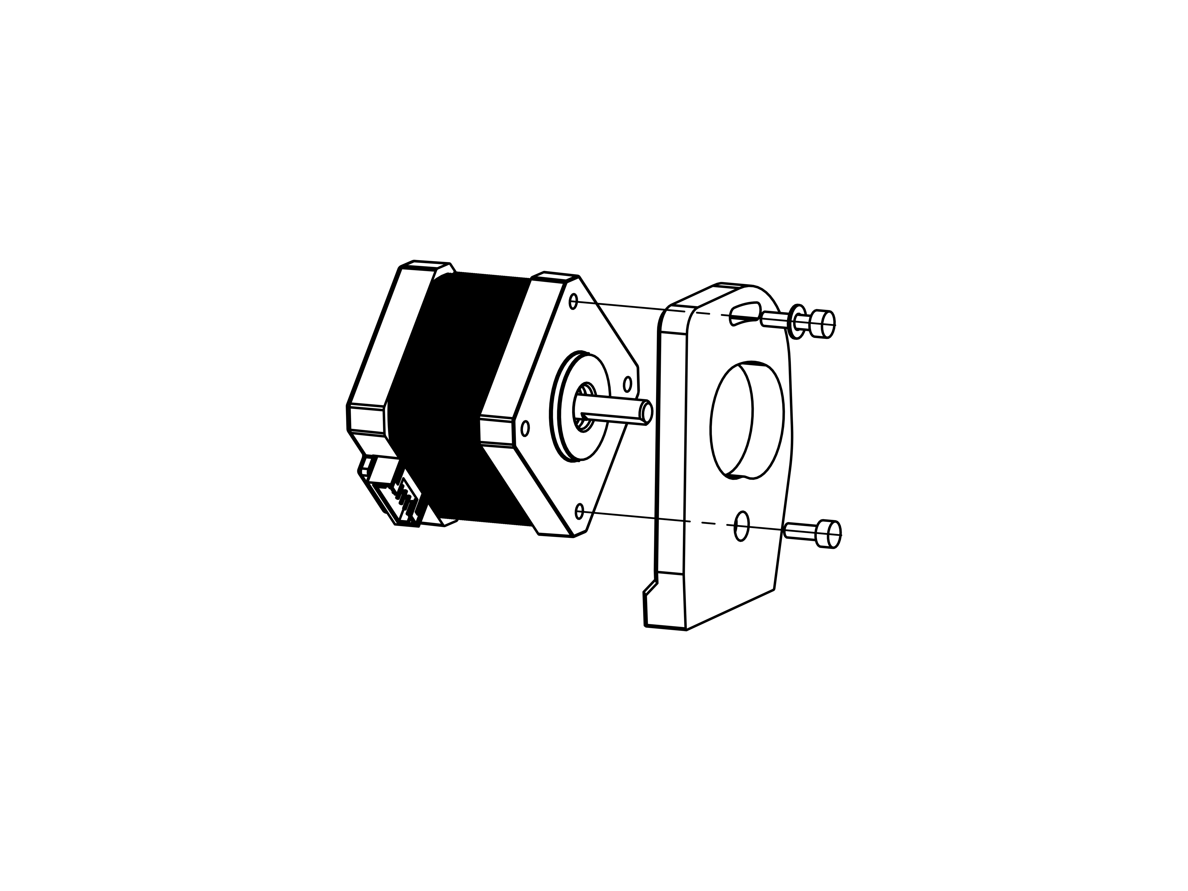
- Attach the DEC motor in the orientation as shown.
- The longer 12mm screw with the washer goes into the long slot at the top.
- The shorter 10mm screw goes into the bottom countersunk hole.
- Just like on the RA motor, the slot is used to tighten the belt.
- 1x DEC motor (long wires)
- 1x M3x12mm & washer
- 1x M3x10mm
- Assembly
- Parts
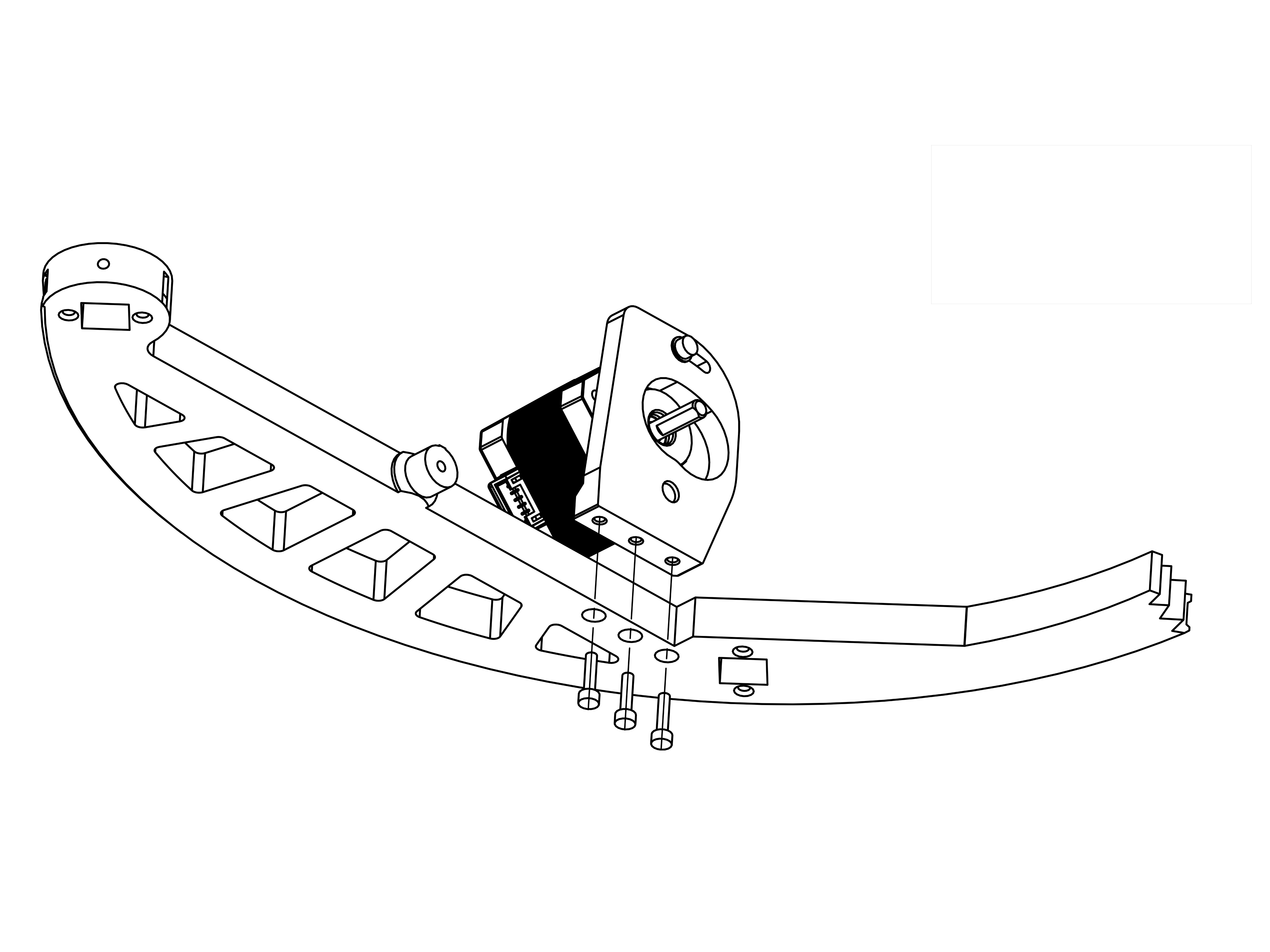
- Attach the DEC motor assembly to the RA Ring with 3 M3x12mm screws as shown.
- 1x RA Ring
- 3x M3x12mm screw
- Assembly
- Parts
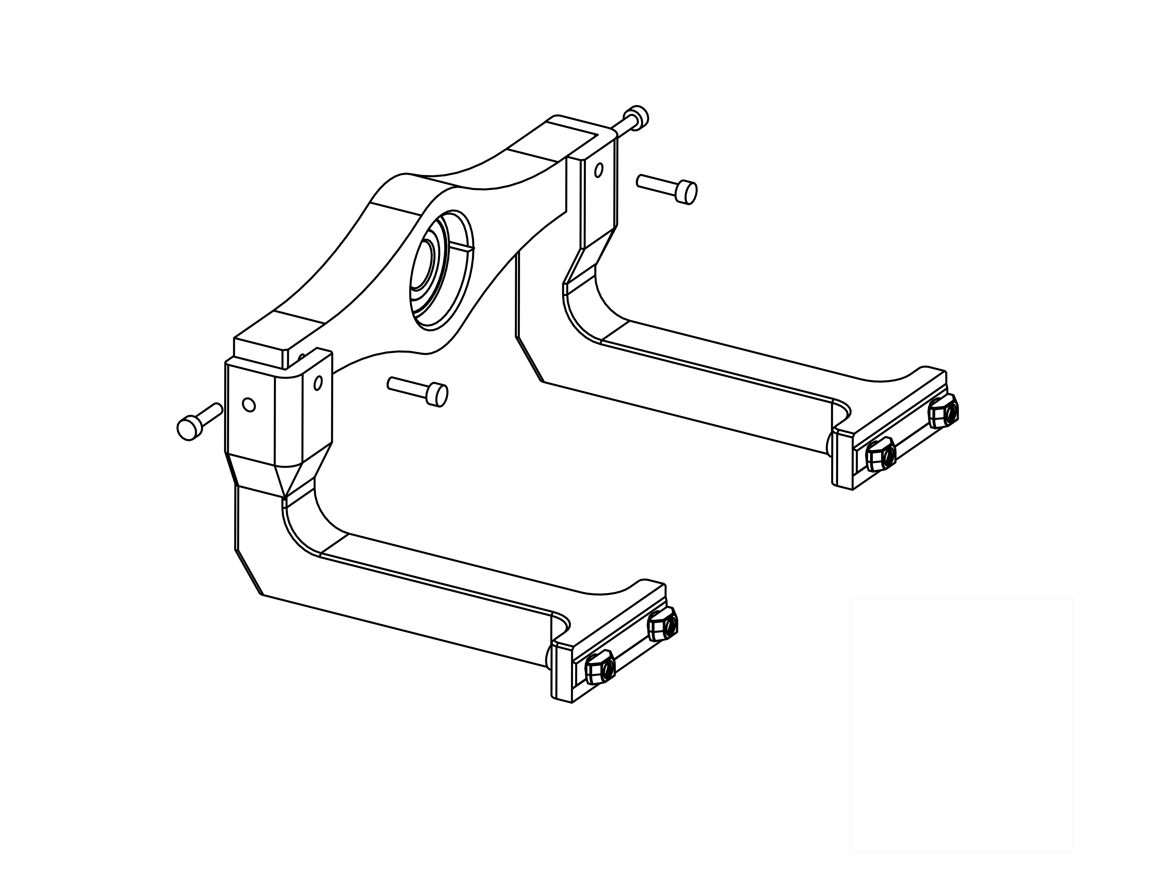
- Take the 2 LHolders for the left side, this is the ones that are slightly longer.
- Screw them to the Bearing Holder with 2 M3x12mm screws each as shown, they will only fit in one orientation.
- Attach M4 & T-Nuts to the bottom part.
- 1x DEC bearing holder
- 2x LHolder left
- 4x M3x12mm screws
- 4x M4x12mm & T-Nuts
- Assembly
- Parts
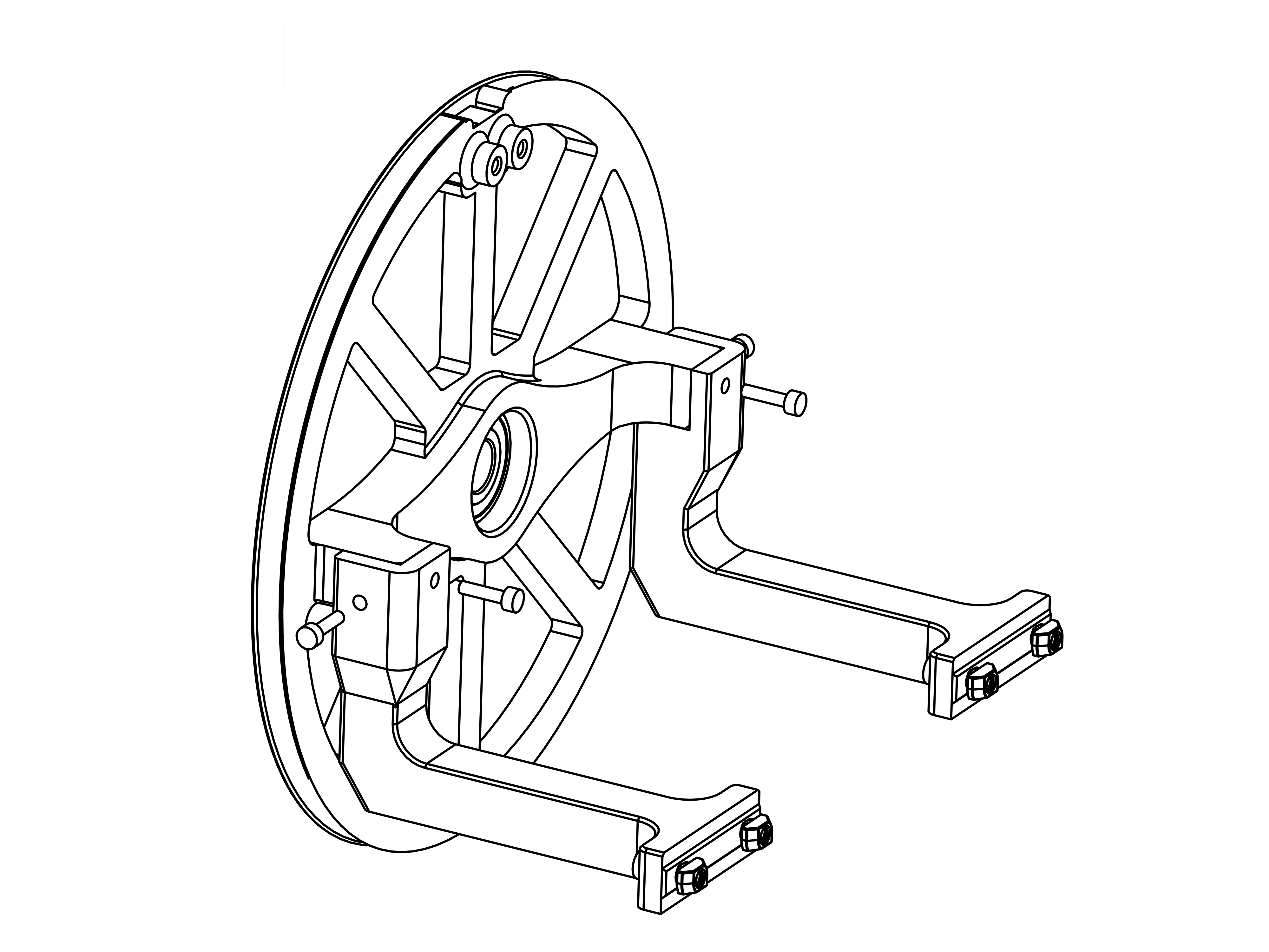
- Take the 2 LHolders for the right side, this is the ones that are slightly shorter.
- Screw them to the DEC wheel with 2 M3x12mm screws each as shown, they will only fit in one orientation.
- Attach M4 & T-Nuts to the bottom part.
- 1x DEC wheel
- 2x LHolder right
- 4x M3x12mm screws
- 4x M4x12mm & T-Nuts
- Assembly
- Parts
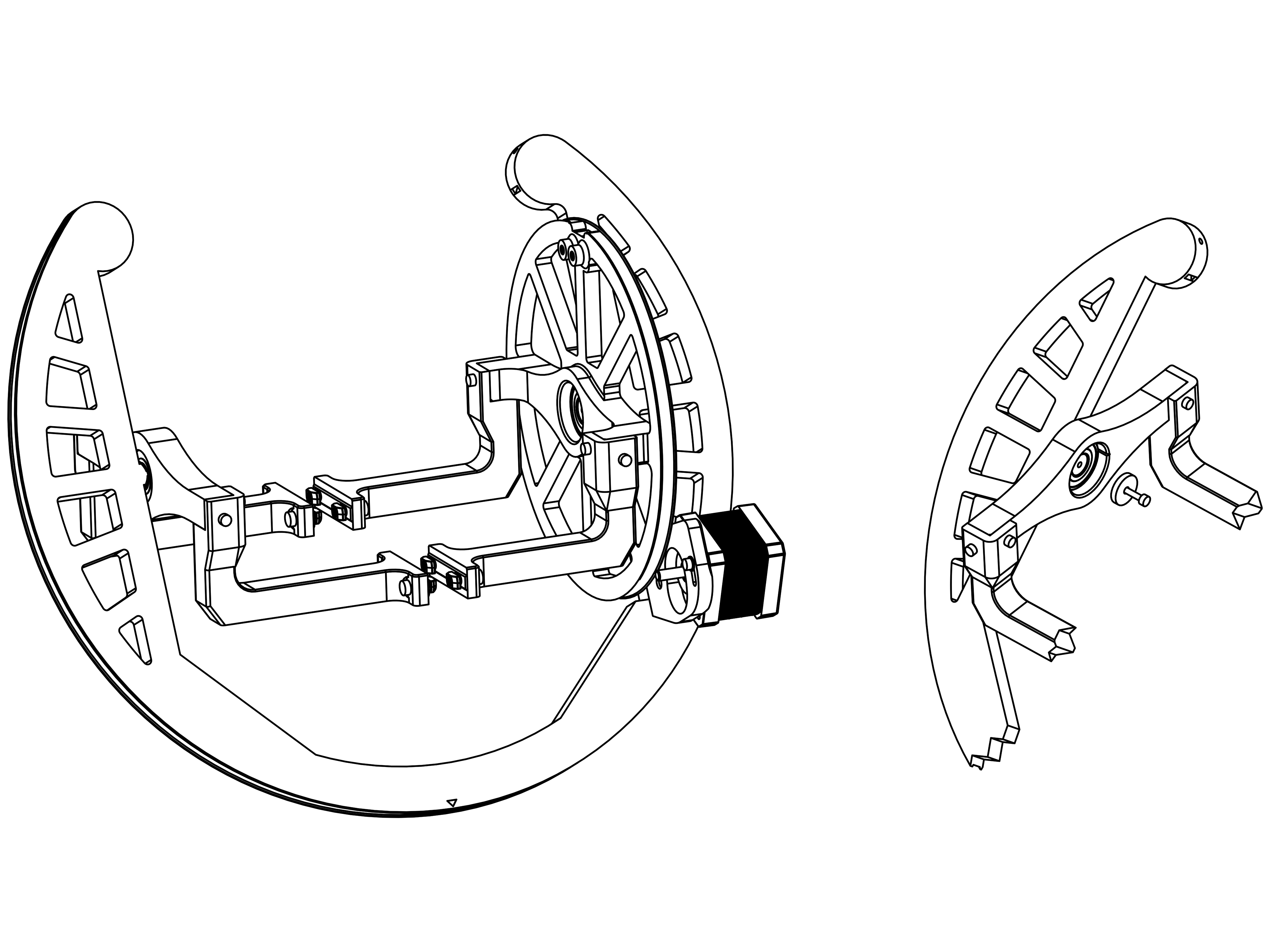
- Attach the DEC wheel and bearing holder to the RA Ring as shown. The DEC wheel goes onto the side with the DEC motor.
- Screw in the printed washers with a M3x12mm screw.
- 2x M3x12mm screw
- 2x printed M3 washer
- Assembly
- Parts
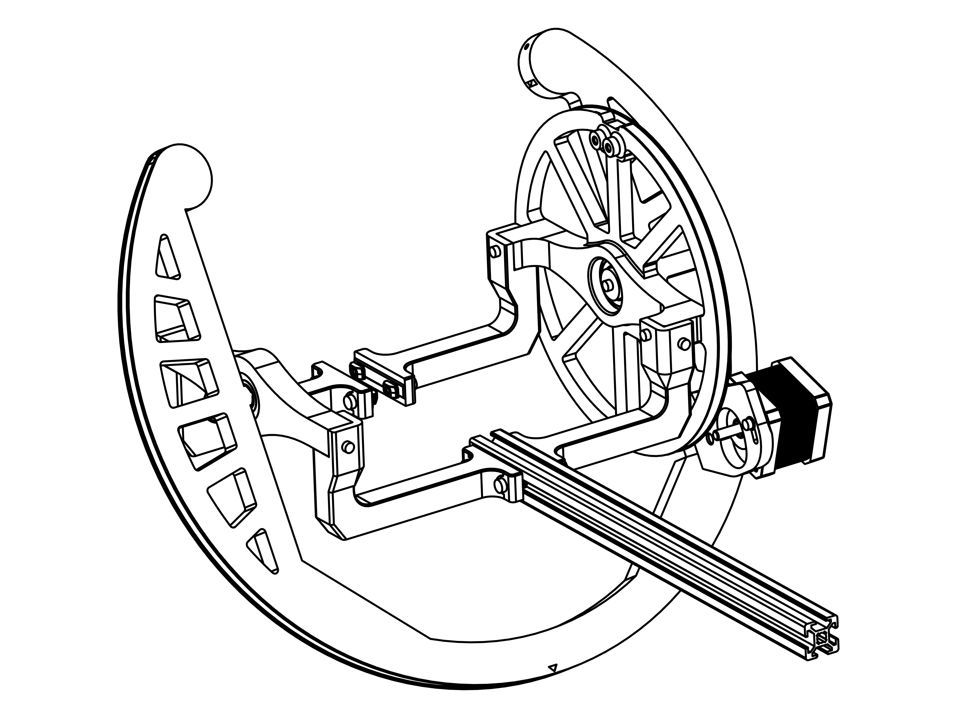
- Take the last remaining aluminum extrusion and insert it in the DEC assembly as shown.
- 1 x 300mm aluminium extrusion
- Assembly
- Parts
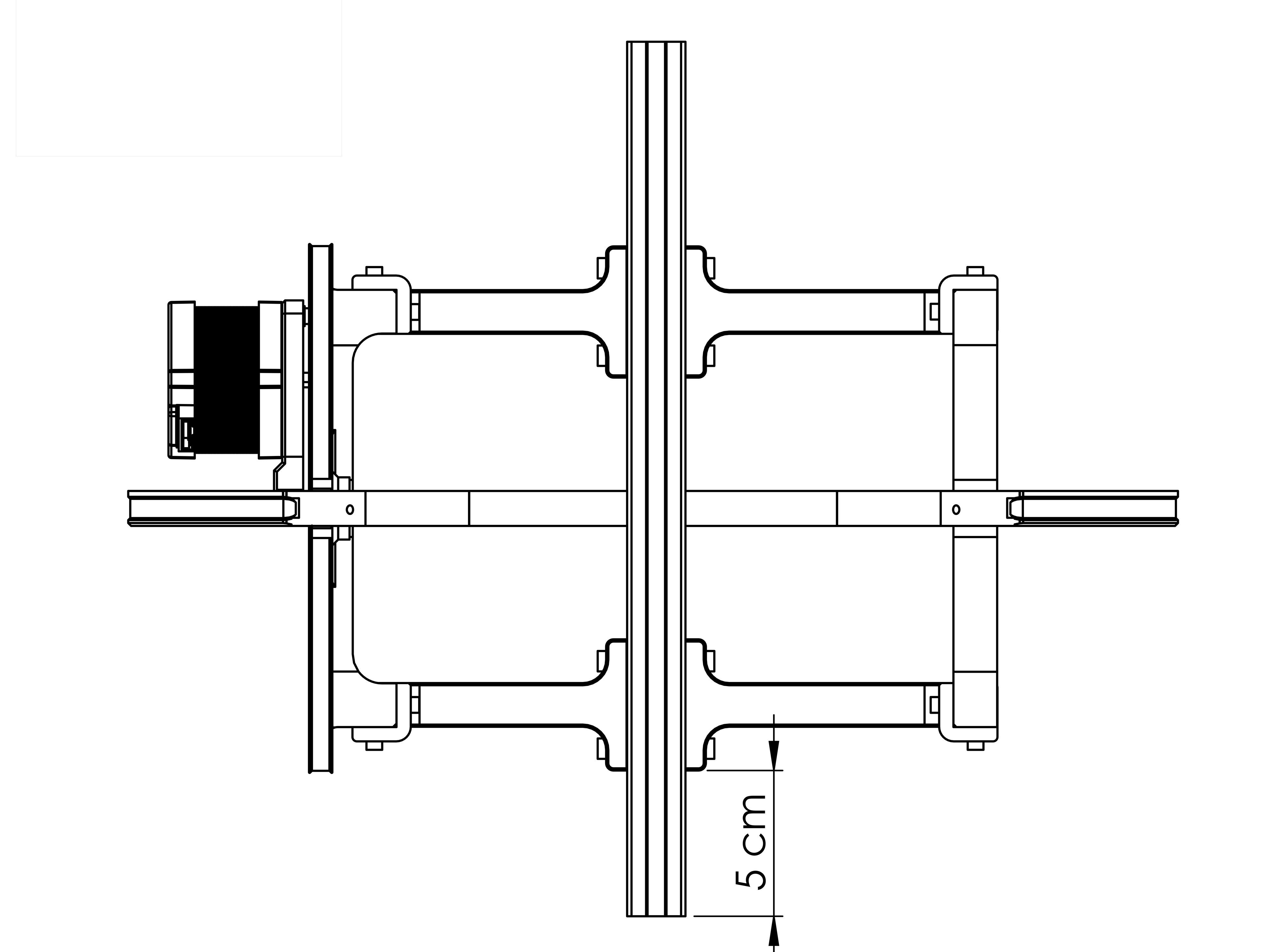
- Push it through as shown, and let it stick out roughly 5cm at the end.
- Assembly
- Parts
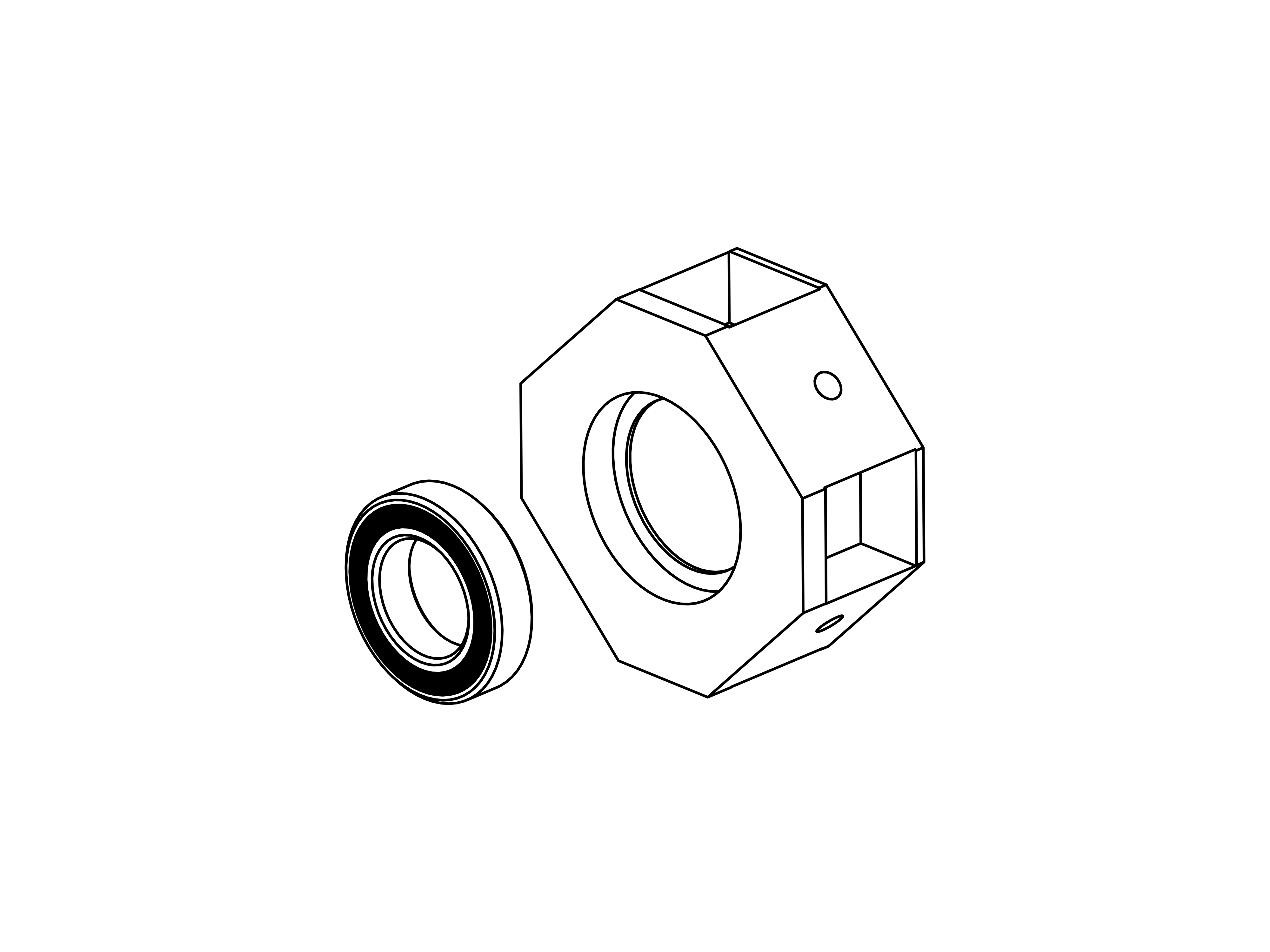
- Push the 6801 bearing into the Polemount.
- 1x Polemount
- 1x 6801 bearing
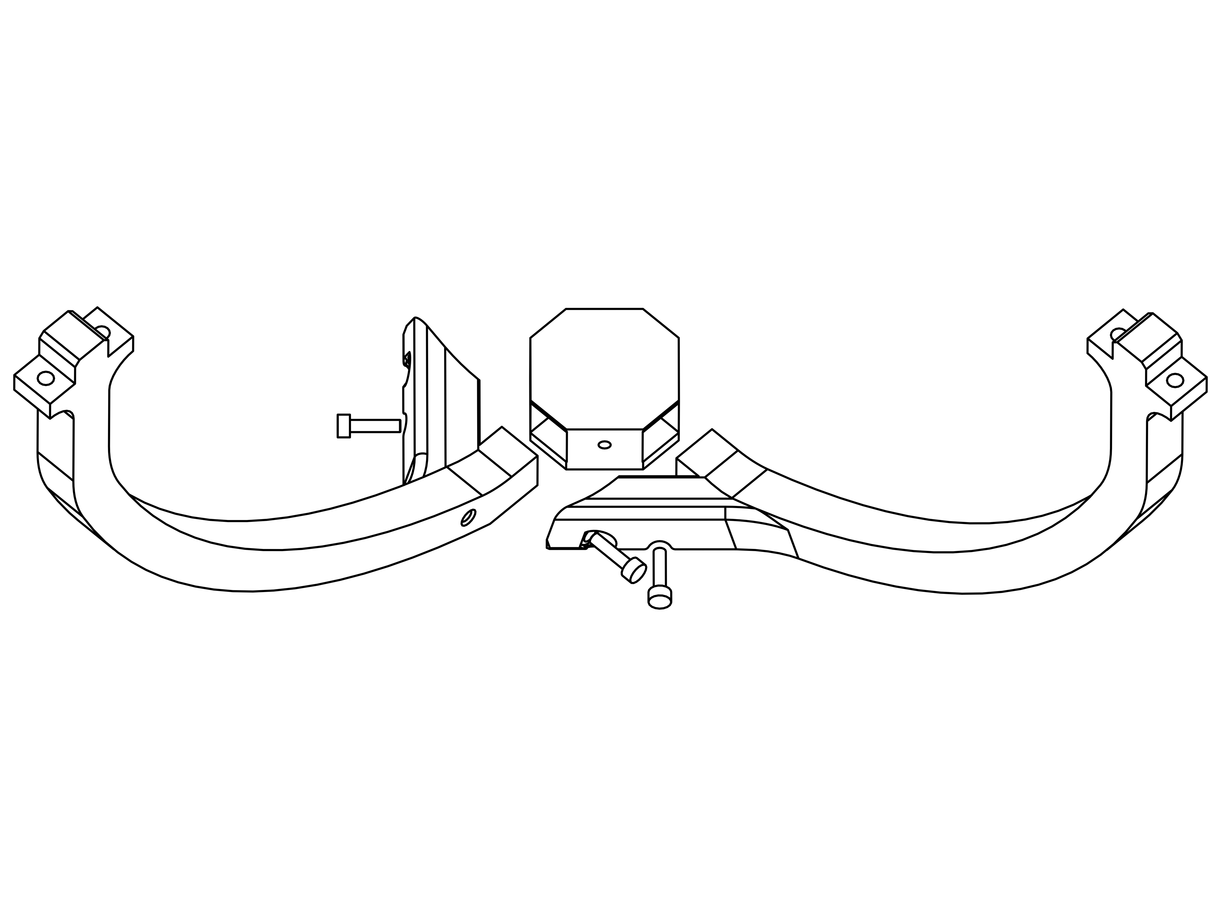
- Assembly
- Parts
- Attach the two Poles to the Polemount with the bearing facing away. Screw 3 M3x12mm screws into the assembly as shown.
- 2x bottom Pole
- 3x M3x12mm screw
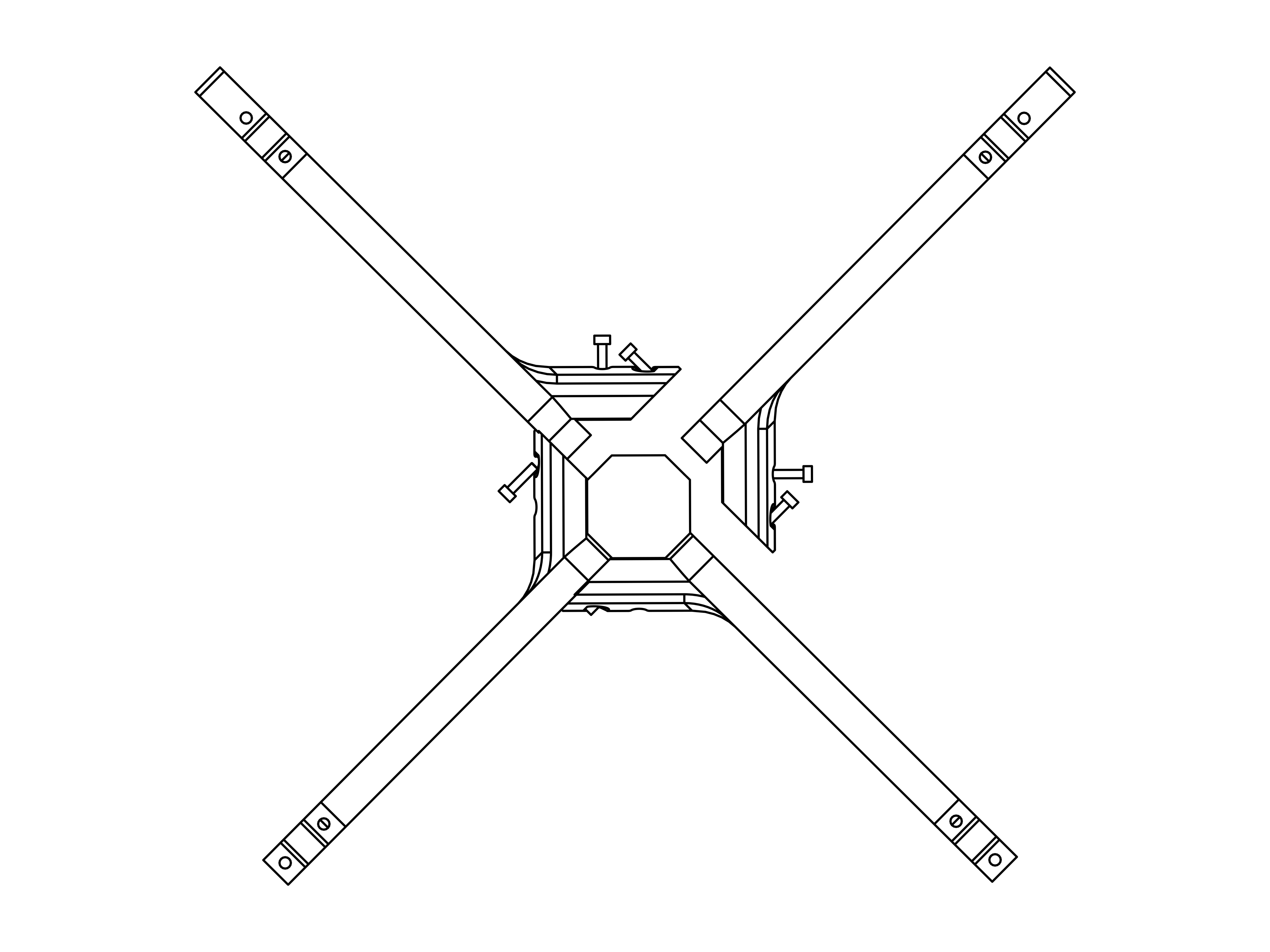
- Assembly
- Parts
- Attach the two top Poles in the same manner.
- 2x top Pole
- 5x M3x12mm screw
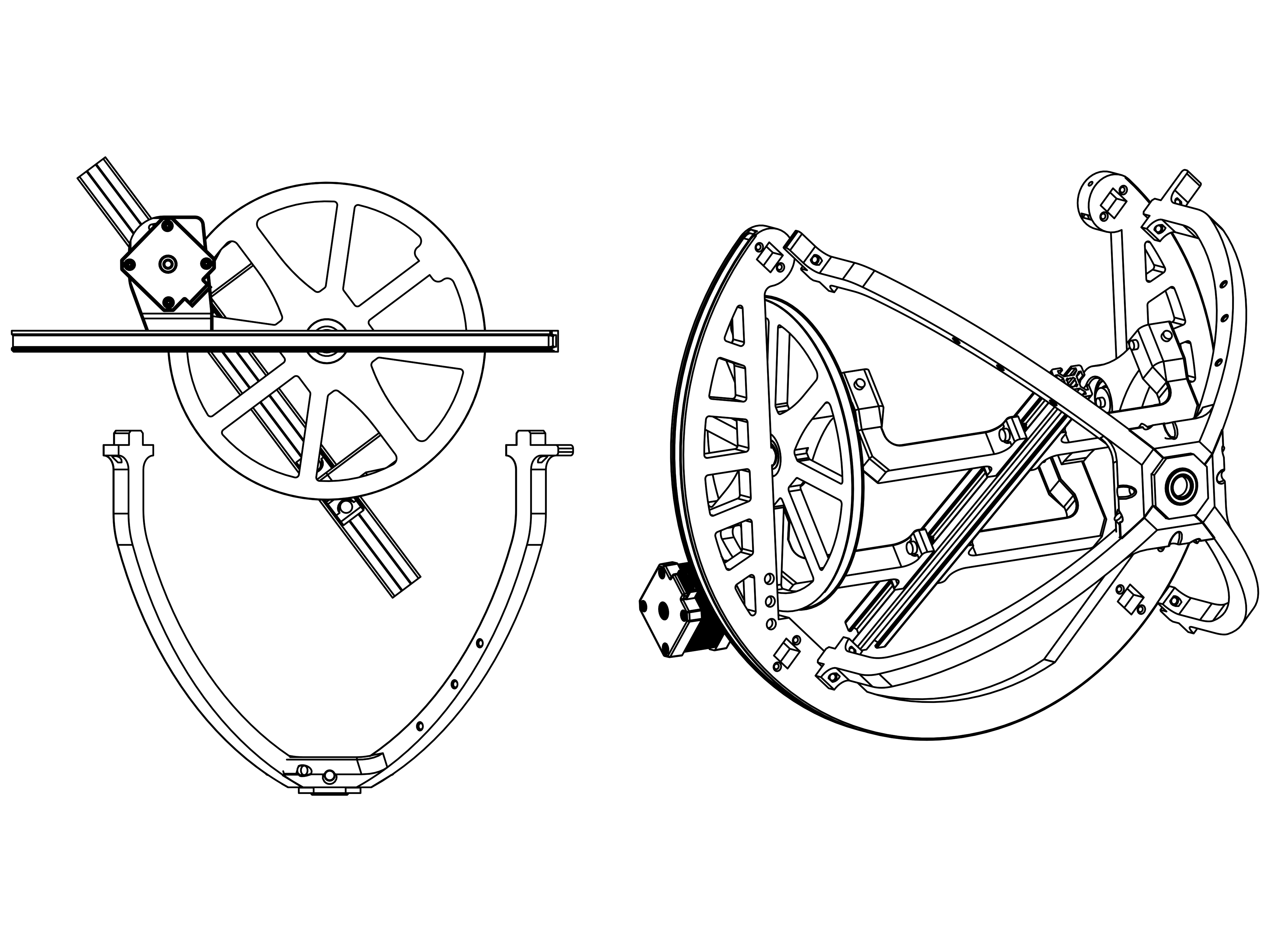
- Assembly
- Parts
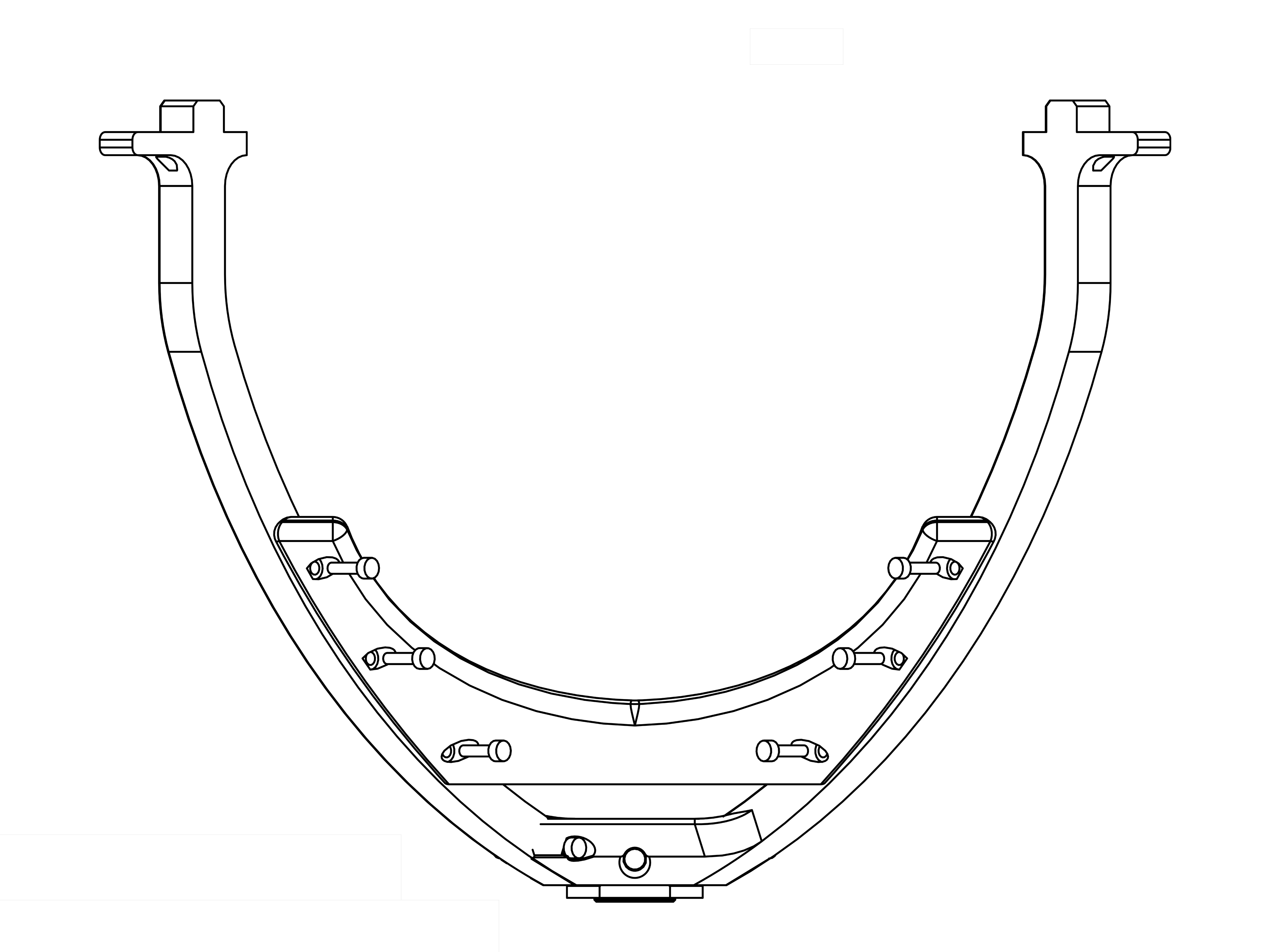
- Attach the Pole assembly to the RA Ring. Note the orientation of the Poles, the two "top" poles have a little knob that sticks out and have three holes in their middle.
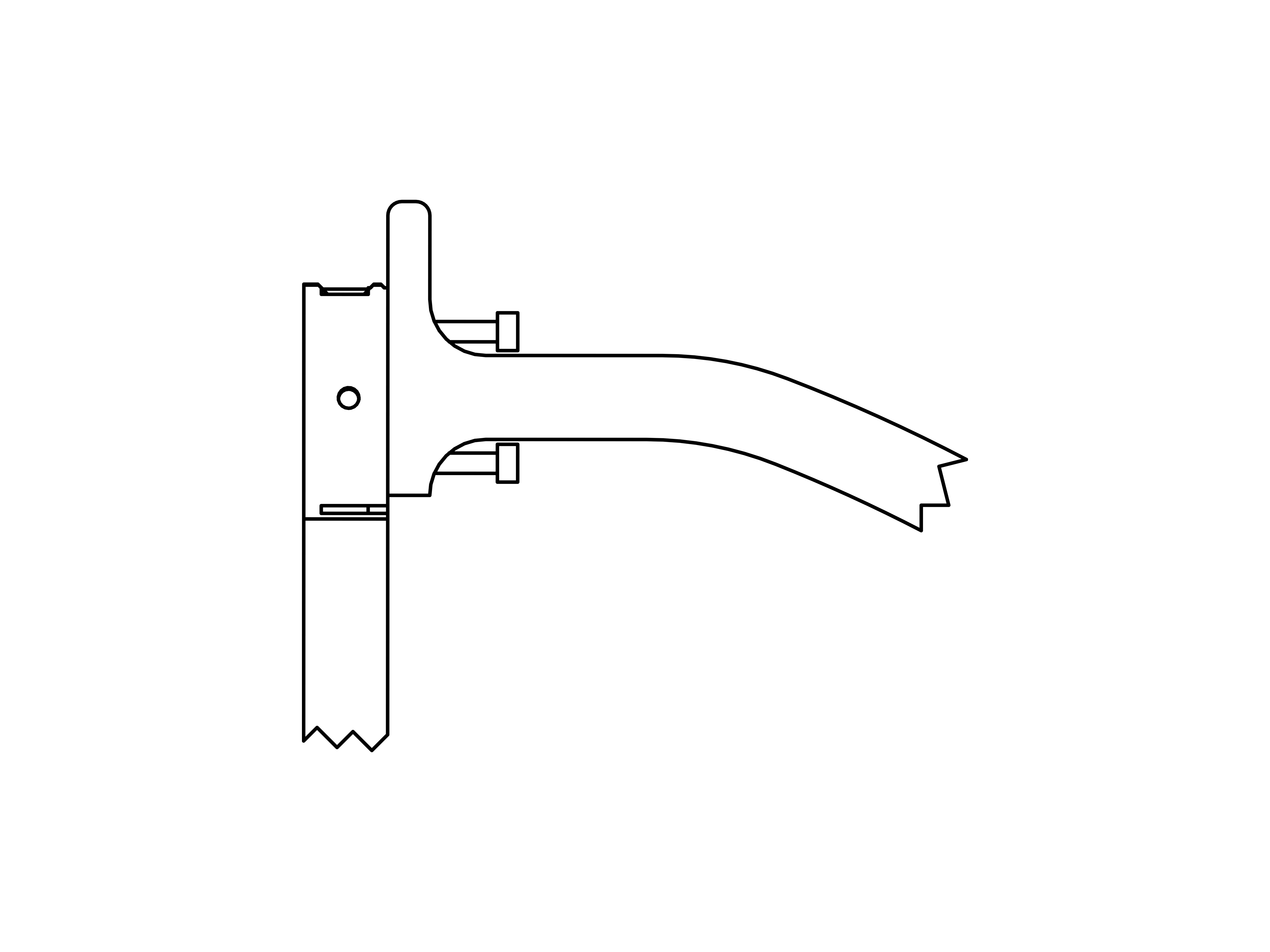
- Assembly
- Parts
- Now use 2 M3x12mm for each Pole to attach them to the RA Ring.
- 8x M3x12mm screws
- Assembly
- Parts
- Attach the Stabilizer with 6 M3x12mm screws to the top poles as shown.
- 1x Stabilizer
- 6x M3x12mm screws
- Assembly
- Parts
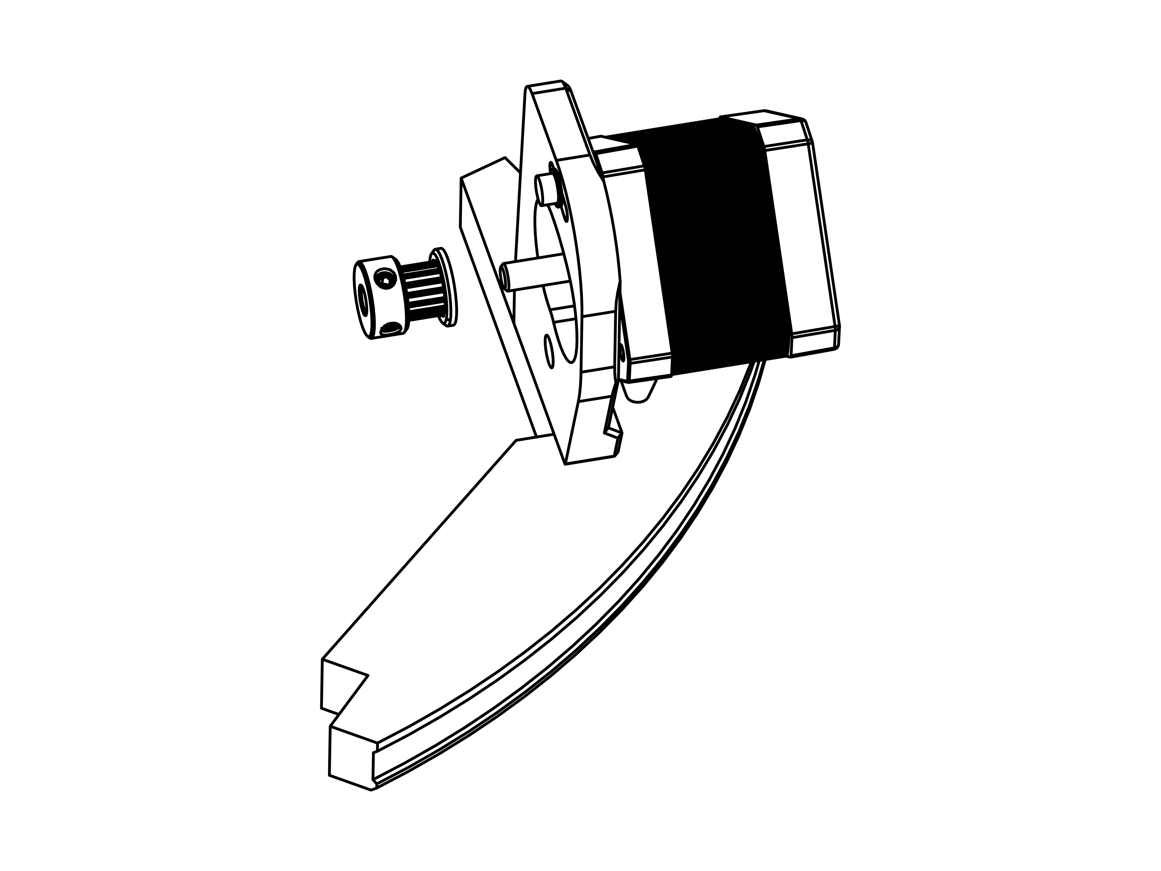
- Attach one of the pulleys to the DEC motor in the orientation shown.
- 1x GT2 Pulley
- Assembly
- Parts
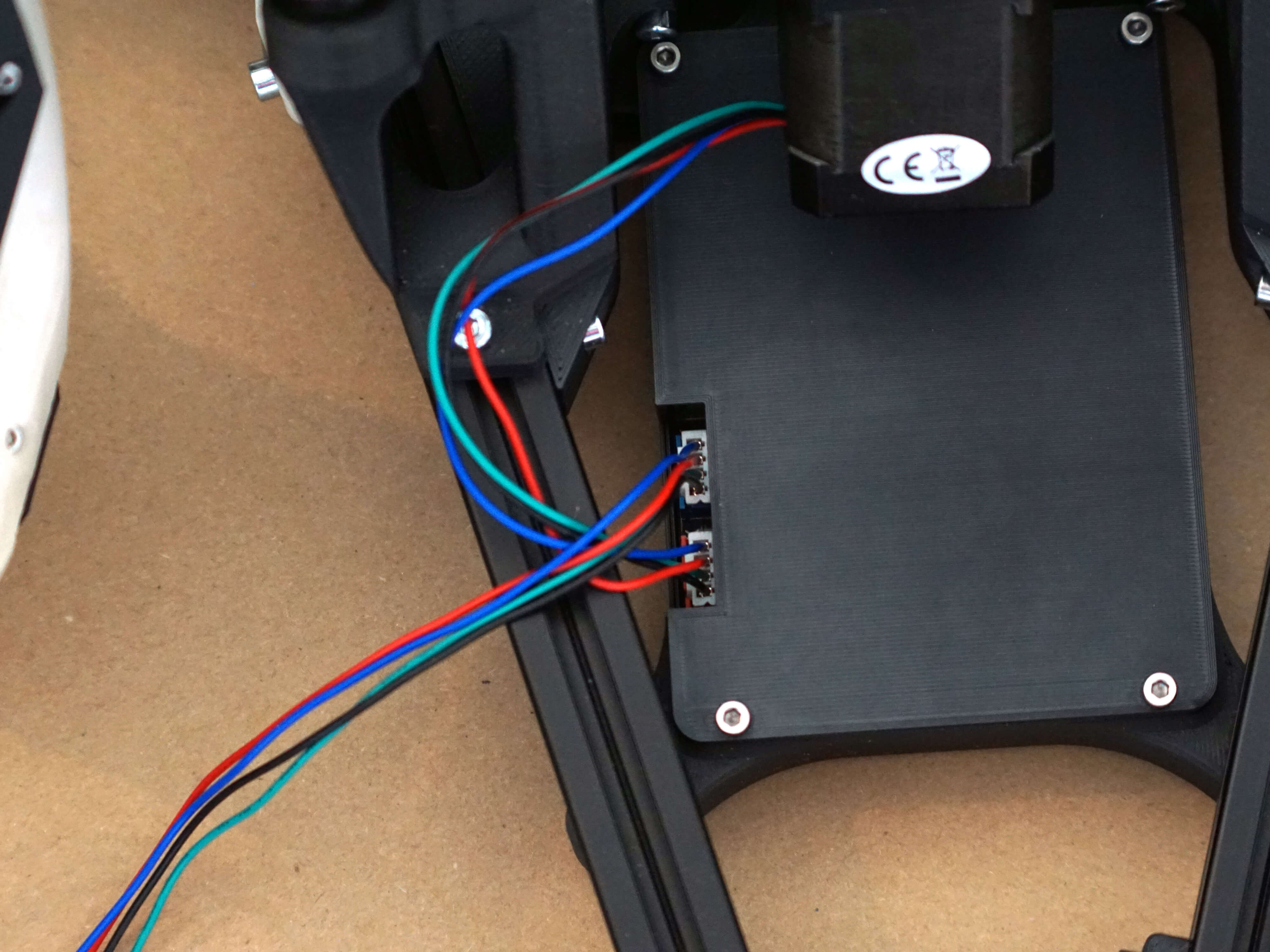
- Connect the DEC Motor to the blue connector
- Assembly
- Parts
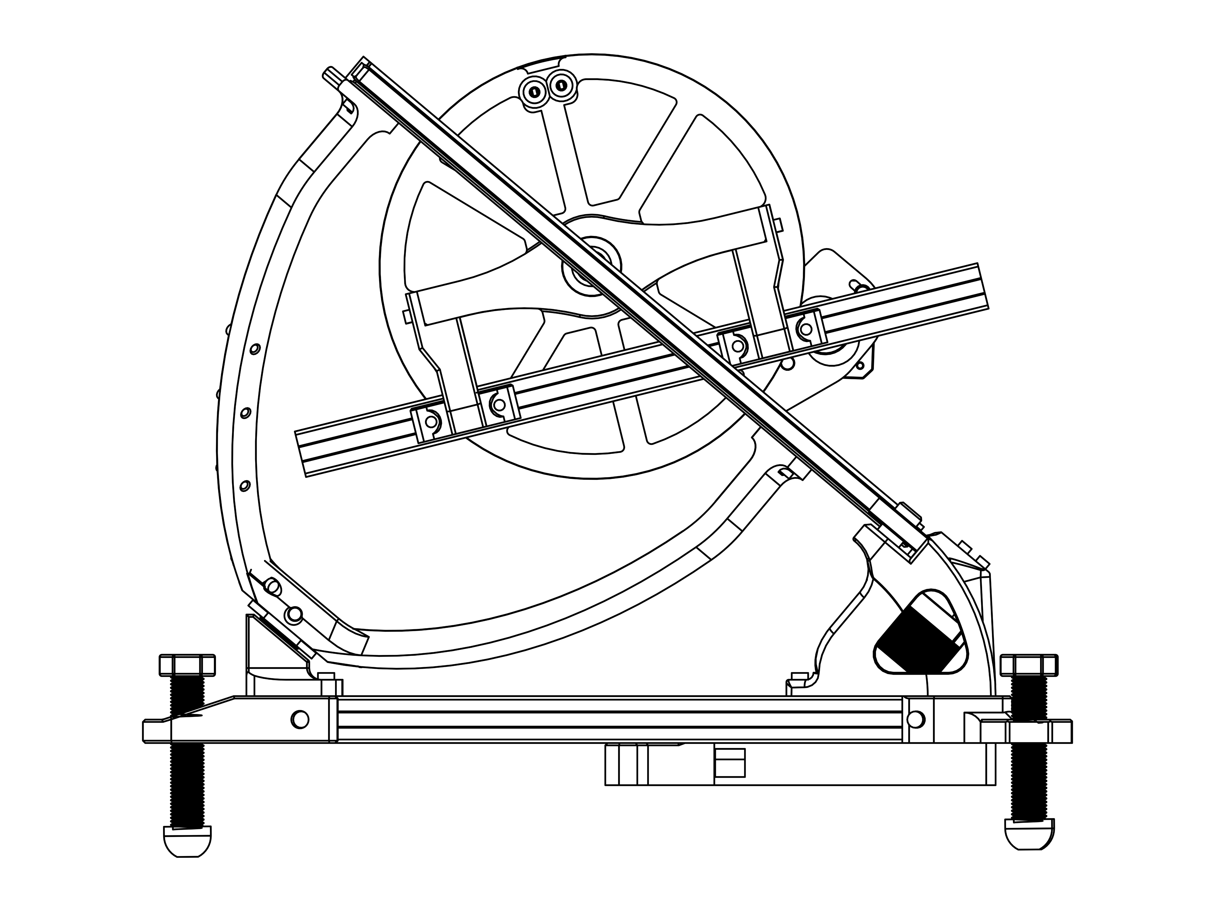
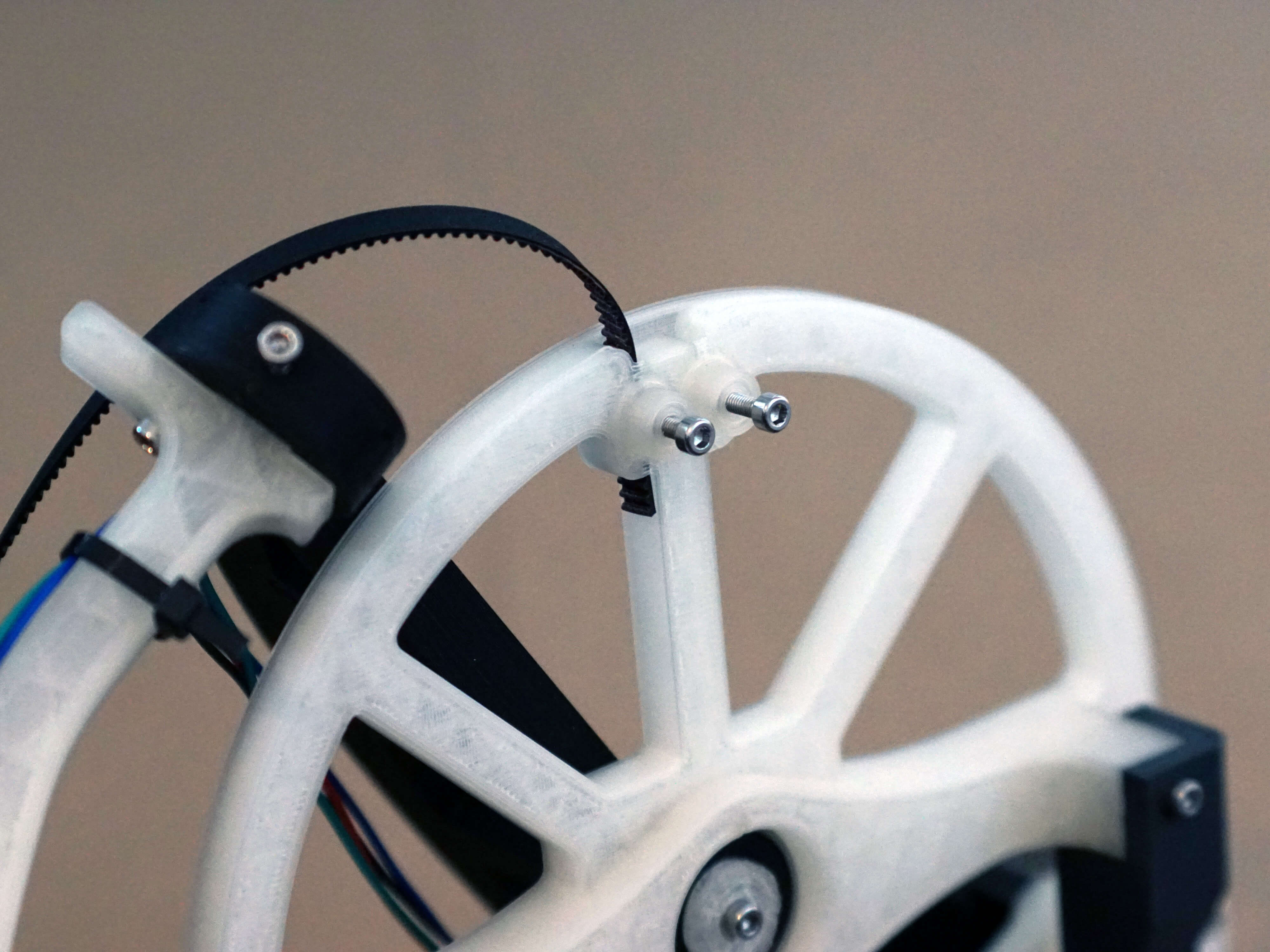
- Finally set the top assembly on the base by carefully aligning the rear bearing.
- Assembly
- Parts
- Push the belt into one slots in the DEC wheel.
- Screw in one of the M3x10mm screws until you can't move the belt anymore. Don't screw in the screw all the way in!
- 1x DEC belt (the shorter one)
- 2x M3x10mm screws
- Assembly
- Parts
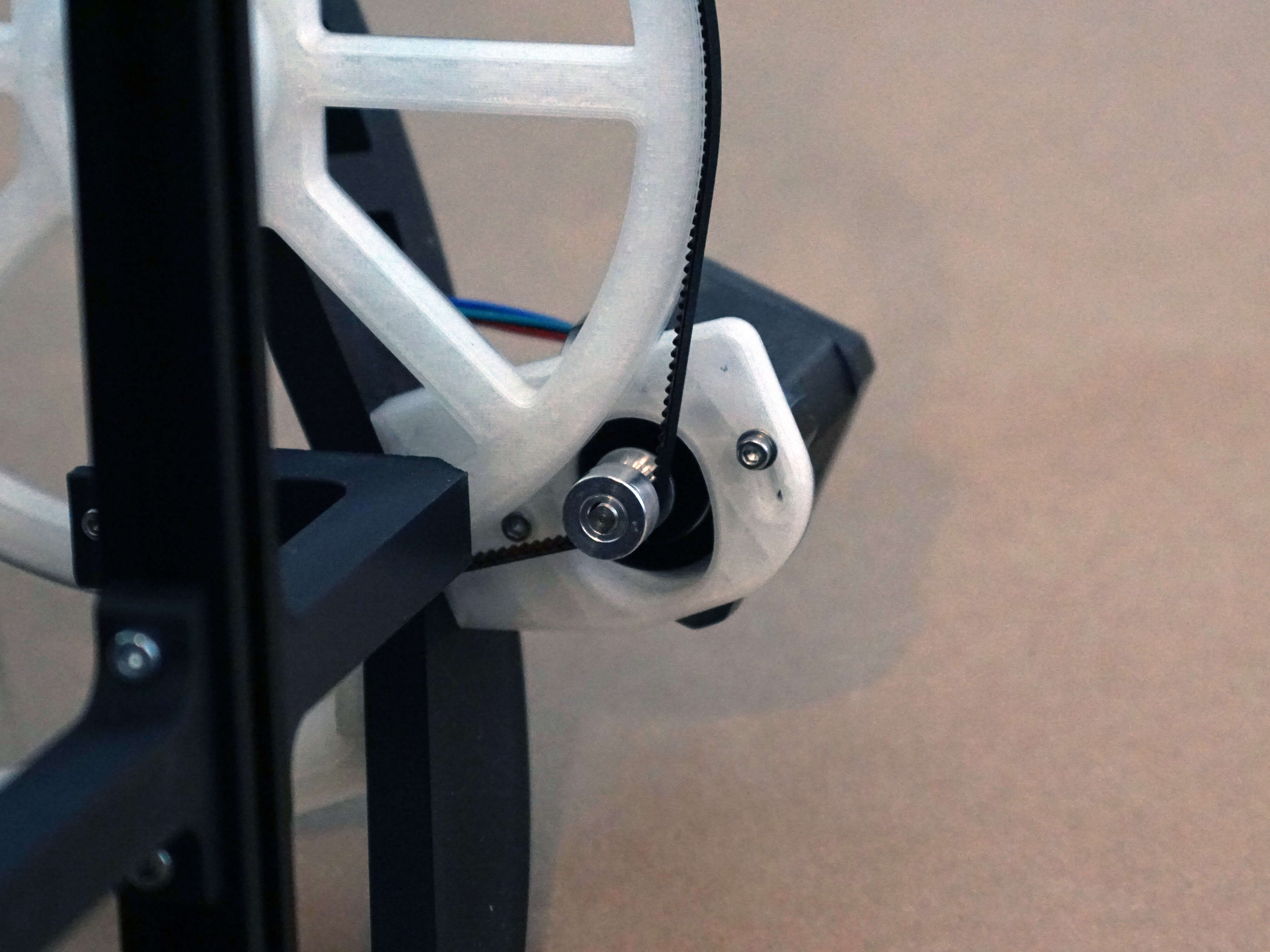
- Route the belt around the DEC pulley.
- Make sure the belt tensioning screw is loose.
- Assembly
- Parts
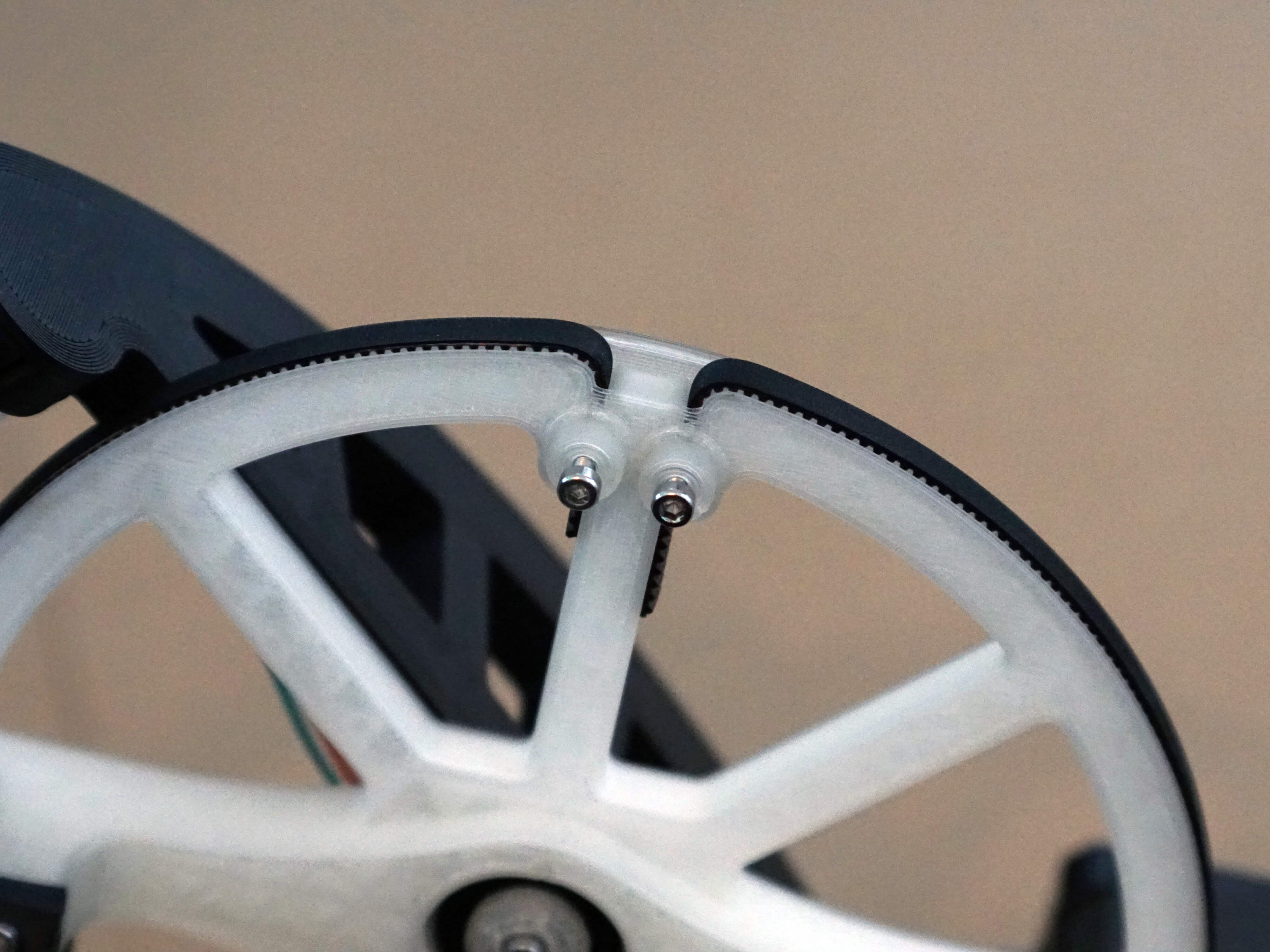
- Push the belt into the other slot and make sure it has some tension.
- Screw the screw in until the belt doesnt move anymore. Don't screw in the screw all the way in!
- Assembly
- Parts
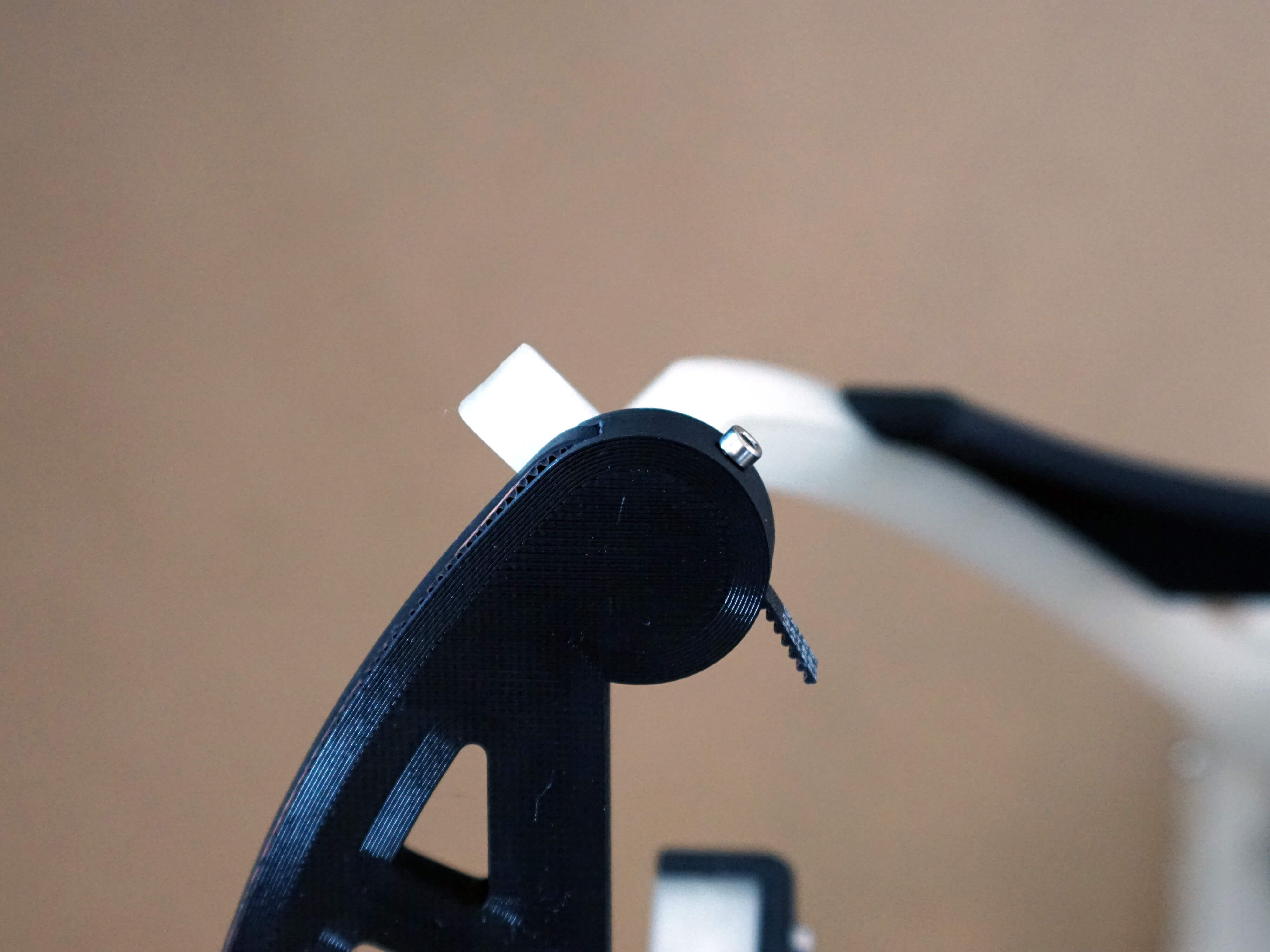
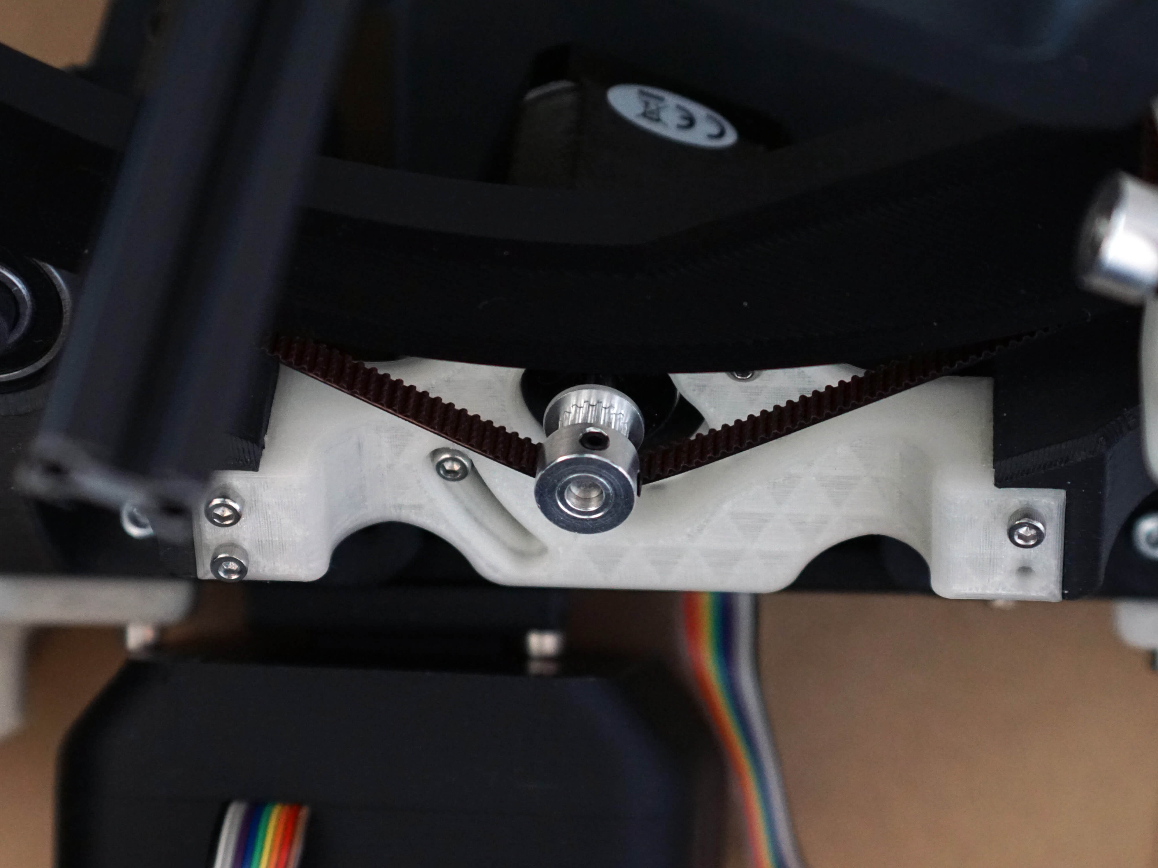
- Push in the RA belt and screw in the M3x10mm screw until the belt can't move anymore.
- 1x M3x10mm
- 1x RA GT2 belt (the longer one)
- Assembly
- Parts
- Make sure the RA motor can slide in the tensioner freely.
- Attach the GT2 Pulley in the orientation shown.
- Route the RA belt around the pulley.
- 1x GT2 Pulley
- Assembly
- Parts
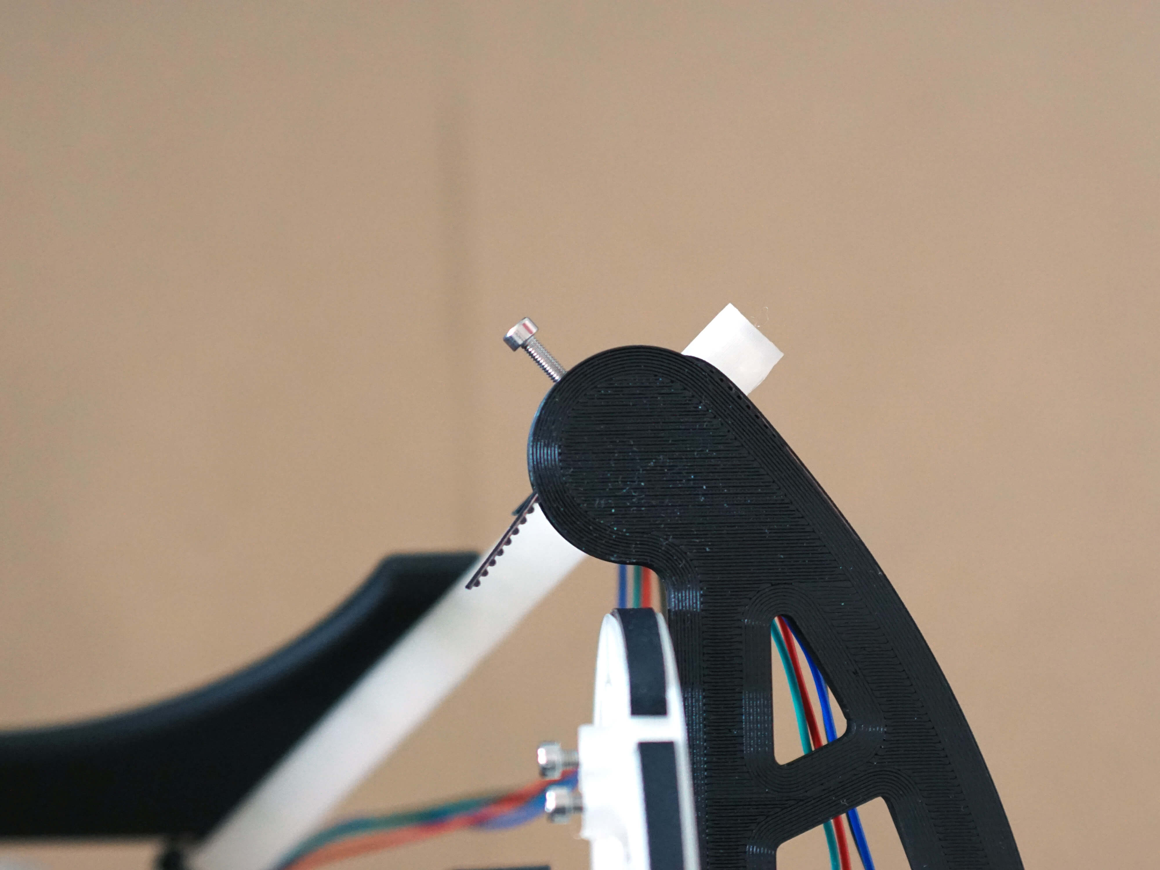
- Push in the belt on the other side and make sure it has a little tension.
- Screw in the M3x10mm screw until the belt doesn't move anymore.
- 1x M3x10mm screw
- Assembly
- Parts
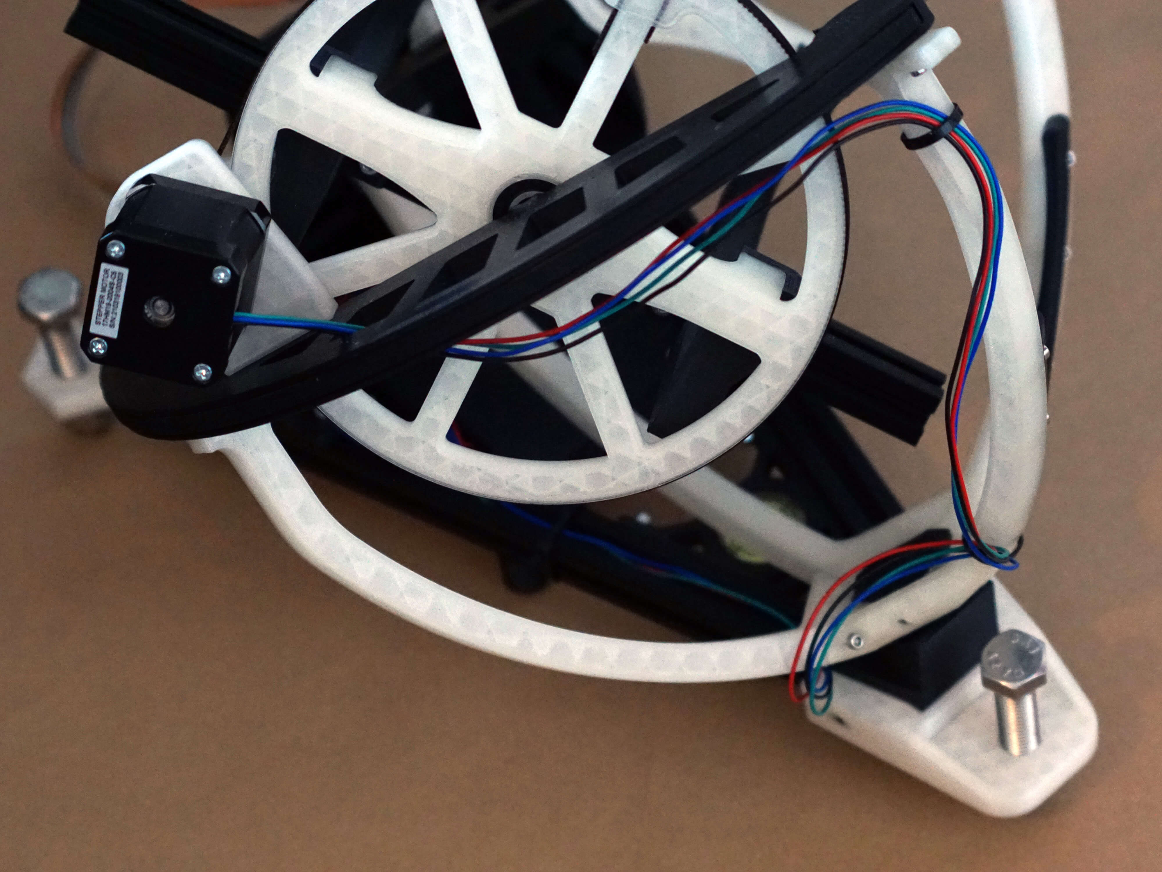
- Route the cable from the DEC stepper as shown and attach it secure it with the cable ties.
- Make sure the RA ring can rotate fully.
- Cut the ends of the cable ties.
- Assembly
- Parts
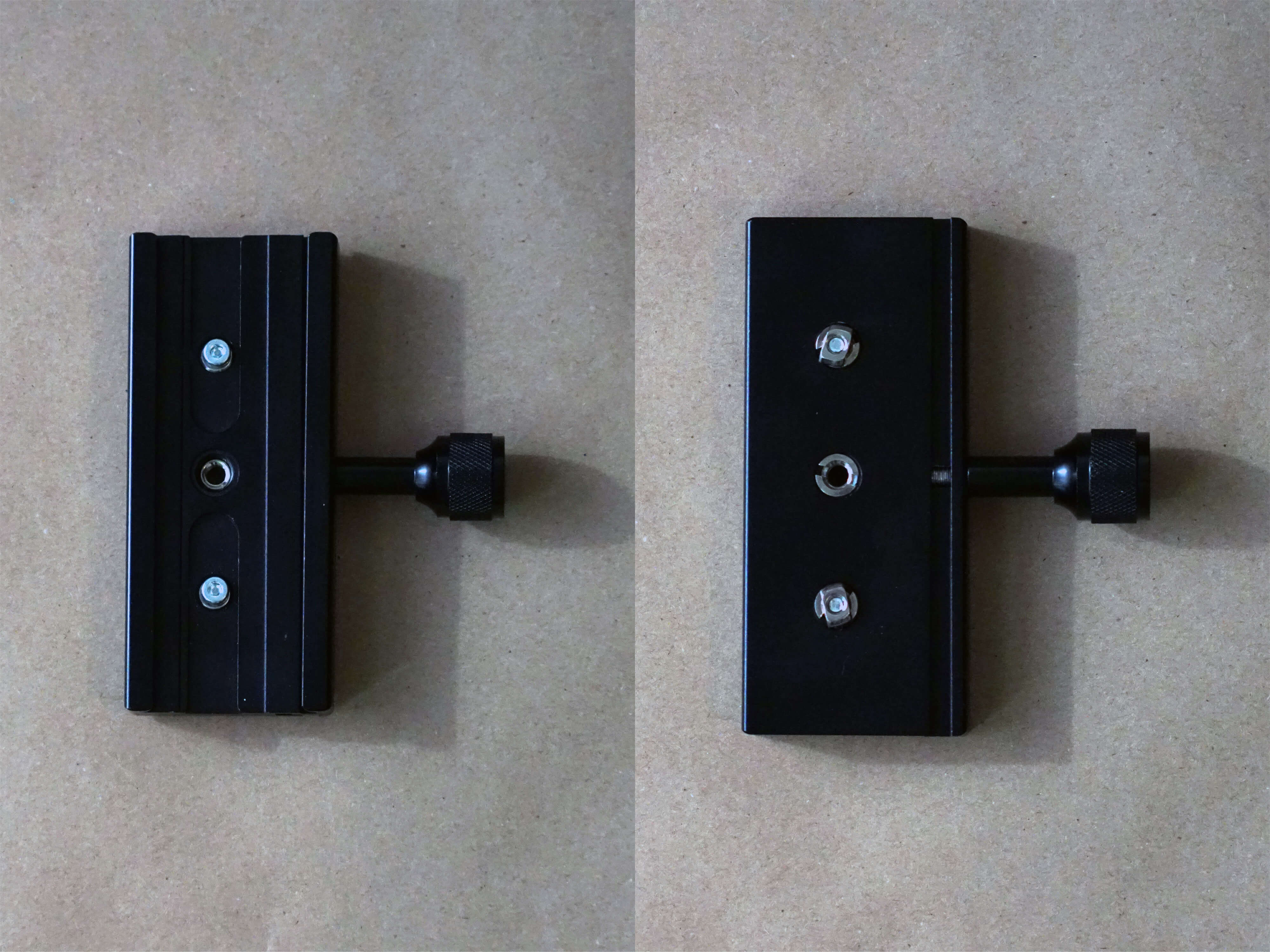
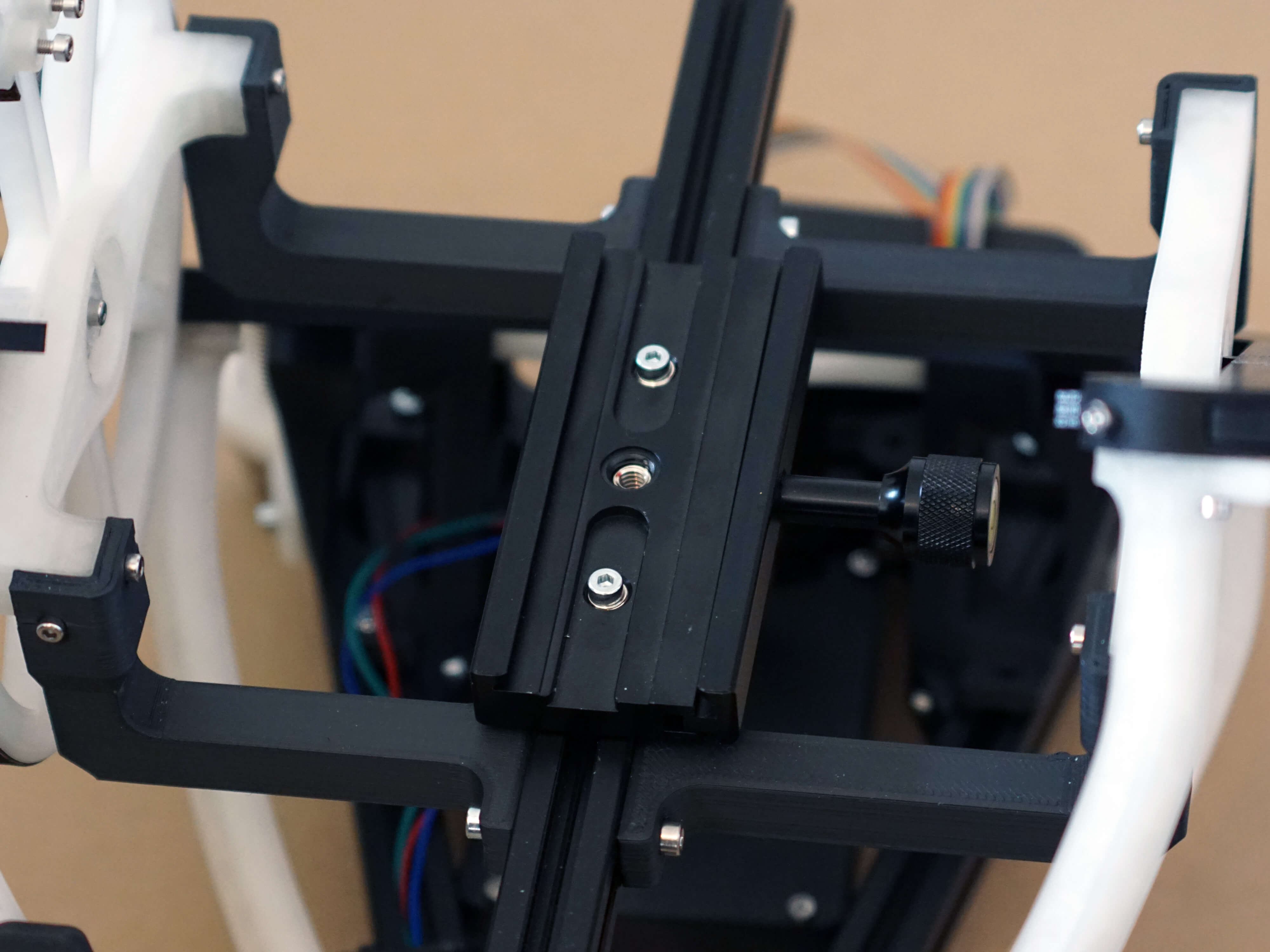
- Attach two M4x12mm screws and T-Nuts to the camera clamp as shown.
- 1x Camera Clamp
- 2x M4x12mm & T-Nuts
- Assembly
- Parts
- Finally attach it to the DEC aluminum extrusion and screw it tight. Have an eye on the alignment to the aluminum rail.
And you're done!
Continue to the Usage page.