The fact that the OpenAstroTracker is printed requires a calibration by everyone. Slight deviations in diameters from printing can have a big impact on performance.
¶ How To Calibrate The GoTo
¶ By measurements
After you have assembled the whole build you can start calibrating the RA and DEC movement. Luckily this can be done inside. Do this with the camera attached.
Start up the Arduino and navigate to the RA menu. Increase the RA by 1h and press the SELECT button. The big wheel should now turn counterclockwise in the north or clockwise if youre in the southern hemisphere. For reference I will always refer as if you're looking at the mount from the front, where the front is the wide part of the mount.

If for some reason the mount turns in the wrong direction, set RA_INVERT_DIR to 1 in your local config file.
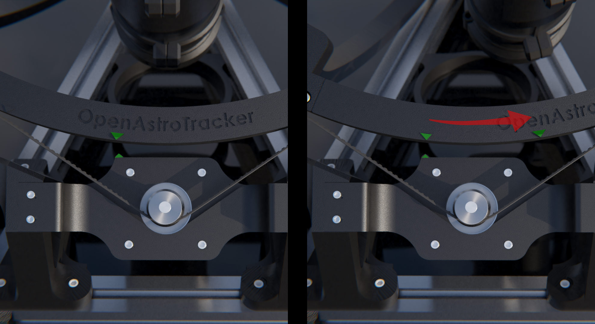
Now, the RA ring has two small markers on the middle part. Those indicate 1 hour RA. Use the CTRL menu to position the marker on the RA motor mount to the bigger marker on the RA wheel. By the way, this is also the home position.
Go to the RA menu and let the mount move 1h RA. If correctly calibrated it should stop at the second marker. If it doesn't, go to the CAL menu in the Arduino LCD, and find the entry RA steps. Press SELECT to enter the submenu, then use the UP or DOWN key to change the value. Press SELECT to save the value. Do this until the RA wheel always moves the right distance, from one marker to the other.
Note: If you end up having to change the steps by more than 10, something is misconfigured and this is not the correct way to fix it. See the troubleshooting page for more details.
The procedure for DEC is very similar.
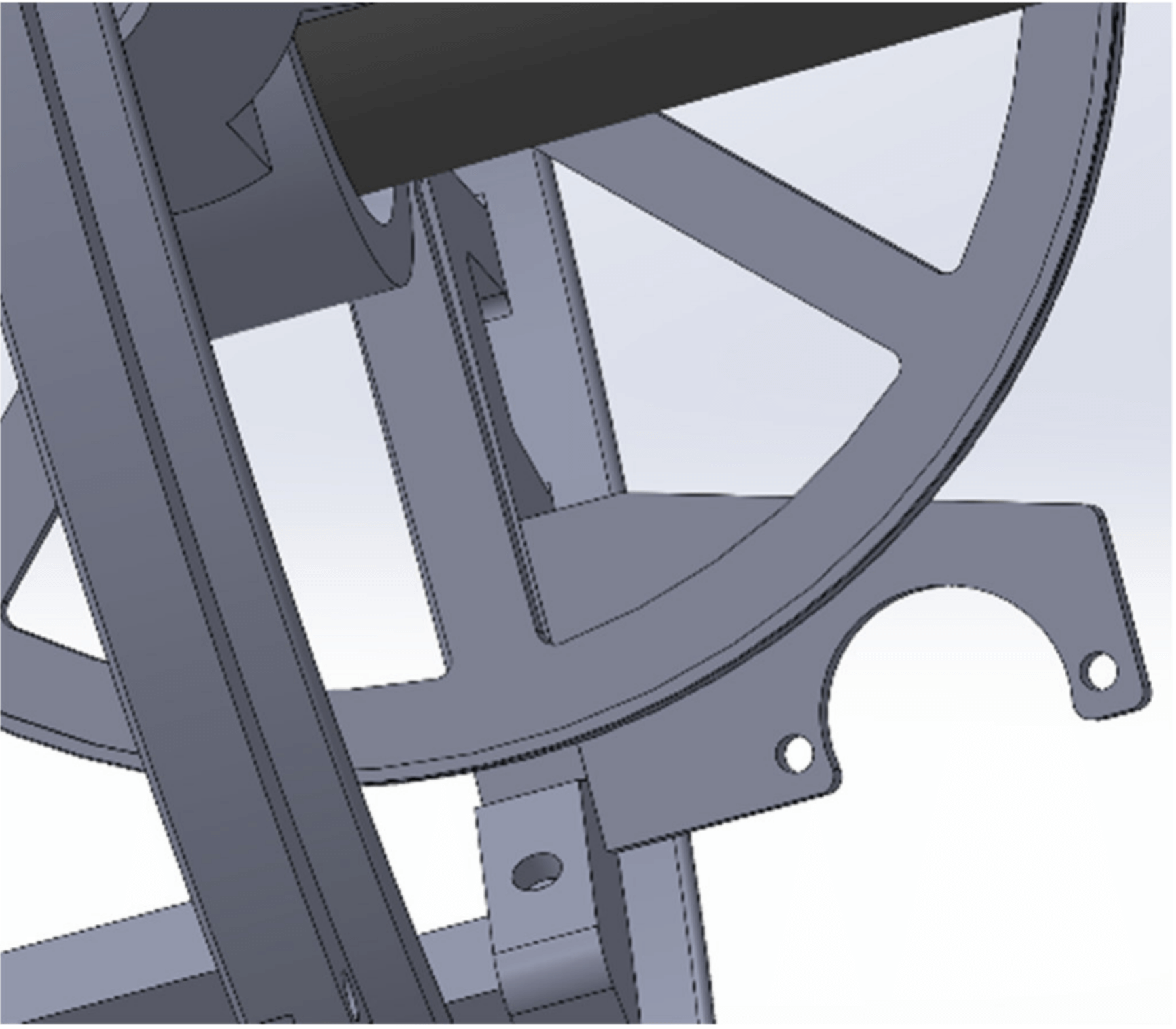
Use the CTRL menu to turn the DEC stepper until one of the struts of the DEC wheel lines up with the other wheel. You can feel this very well with your fingers.

Navigate to the DEC menu. It should show 90°(-90° in the southern hemisphere) by default. Decrease it to 45° (-45° in the southern hemisphere) and press SELECT. The camera should now be move to the next strut (in either direction). After the move is finished, the DEC wheel should have rotated 45°, you can see that very well because the next strut should be aligned again. It's probably easiest to feel by placing fingers around it and feeling when the strut is centered next to the RA ring. If it doesn't move 45°, adjust the value DEC steps in the CAL menu, just like for the RA steps.
That confirms that the distance is correct.
To check that the direction is correct, you can use either OATControl or the LCD.
- With the LCD, go to the
CTRLmenu, selectManual Controland then press and hold the Up button for a few seconds. - With OATControl, connect and click and hold the large up arrow triangle for a few seconds.
The DEC ring should rotate such that the front of the DEC alu profile (or the lens of your camera) goes upwards.
If it moves down, you can either flip the wiring for the DEC stepper or simply set DEC_INVERT_DIR to 1 in your local config file.
Note: If you end up having to change the steps by more than 1%, something is misconfigured and this is not the correct way to fix it. See the troubleshooting page for more details.
¶ By platesolving
Follow the instructions on the steps calibration spreadsheet
¶ How To Calibrate The Tracking Speed
If your RA Steps are calibrated well, the tracking speed will be very close to perfect as well. However, sometimes it is necessary to calibrate the tracking speed manually. For this, you'll have to do real exposures.
Set up the mount and polar align it well. Move the DEC axis away from the home position, ideally somewhere around 0° DEC. Take exposures with increasing time. So 30s, 60s, 90s, etc. until you get obvious and long star trails.
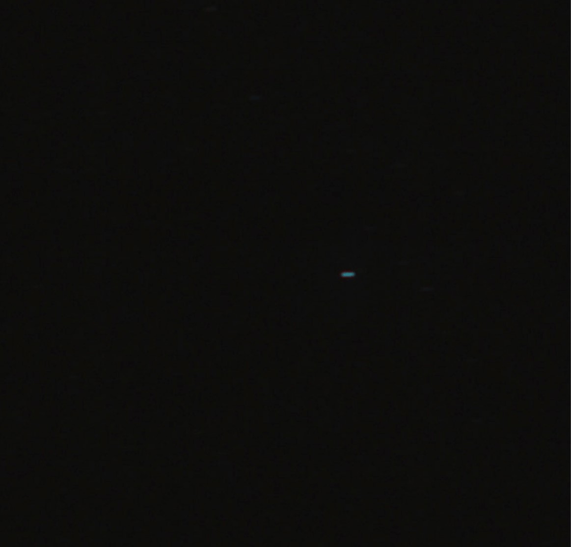
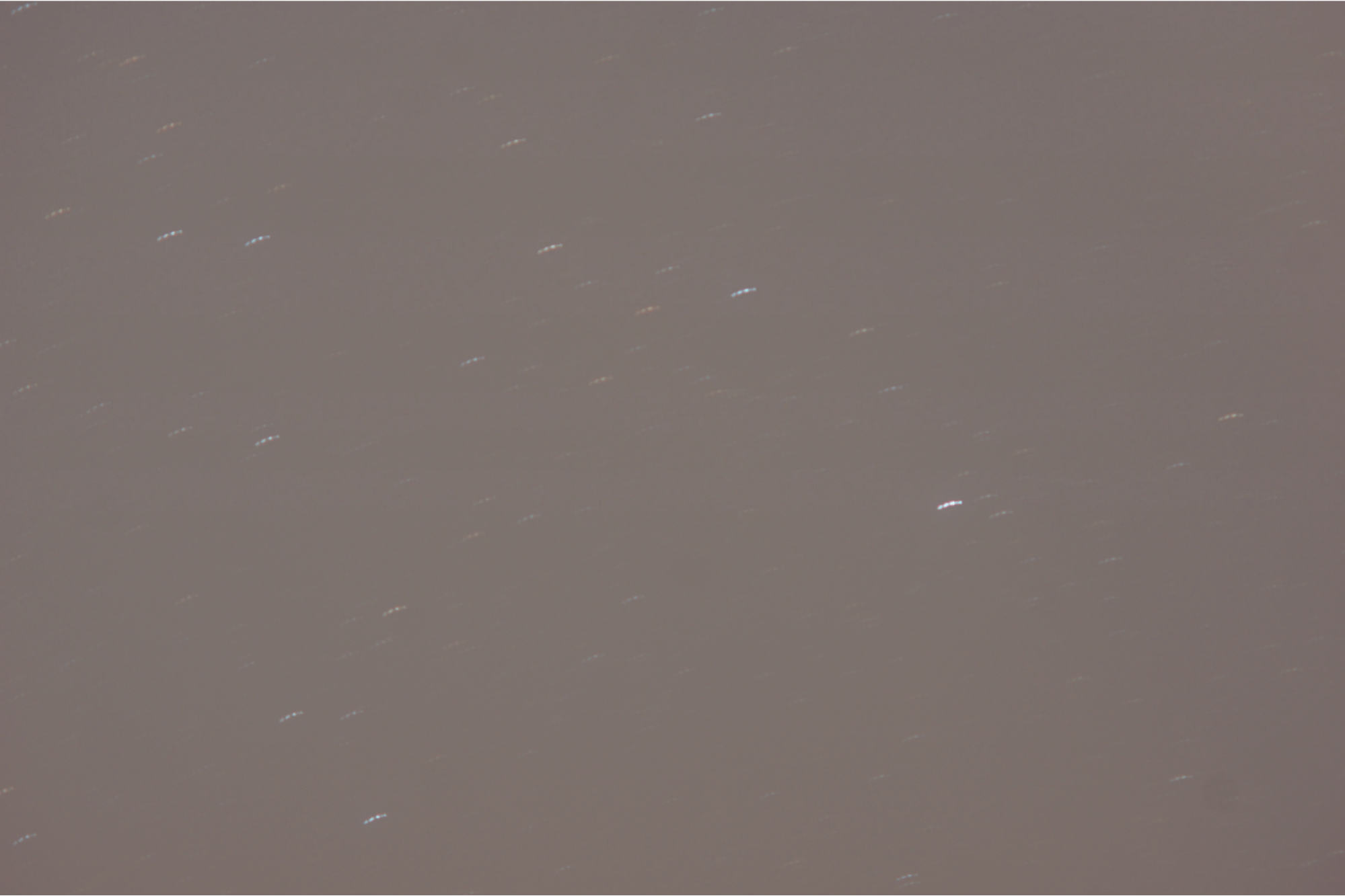
What you want: Straight, solid trails. This means a tracking error that we want to calibrate. Note: If the trails are straight up to down, not right to left, they are caused by bad polar alignment rather than a wrong tracking speed value.

What you don't want: Dotted, curved etc. trails. This means some other error, like a cable snagging, bump in the RA wheel, passing truck, wind, etc. See the Troubleshooting page for these errors. (click to enlarge the image)

To rule out random errors like the ones mentioned, always take at least 3 exposures. Only adjust the tracking speed if the error stays consistent in all exposures, with the star trails being the same length and shape. Otherwise you will be trying to fix another error that’s not correlated to tracking speed.
Repeat until you get consistent exposures.
TIP: Aim for a much higher exposure time than you would actually use. So if you want to use 1 minute exposures, use 3 minute exposures to calibrate. Even if you cant get the 3 minute exposures perfect, the 1 minute ones will still be good.
To adjust the tracking speed, navigate to the CAL menu and the submenu Speed calibratn. It should be 1.0000 by default. Decrease or increase the value, see if the trails get better or worse, repeat. By pressing SELECT in this menu, the value you entered will be saved even when the Arduino is powered off.
¶ How To Calibrate The "Roundness" Of The RA Ring (experimental)
This procedure isn't very streamlined but works without new parts. I may change some parts to make this easier in the future.
Perfect roundness is very critical to the function of OAT. Should, for some reason, the RA ring not be a perfect circle, this will have a big effect on largely Polar alignment and to a lesser degree trackingspeed. If you noticed your Polar alignment not being consistent, this might be the issue.
What you'll need:
- Assembled and powered OAT
- Universal mount (alu mount) makes it easier
- A laser pointer (works best) or a camera (should work but i haven't tested)
What to do:
I will talk about the procedure with a laserpointer, but it is mostly the same should you use a camera. In that case attach the camera to OAT and arrange it so you can focus to a wall. Stick something to the wall or so, you'll need a reference point.
- Remove the belt from the RA stepper. Tighten it around the ring so you can move the RA wheel easily and freely side to side, but its still rolling on the belt.
- Attach the laserpointer to the aluminum profile of the universal mount. Make sure its straight.
- Power on OAT and move DEC roughly to the home position. Power on the laserpointer. Arrange OAT so the laser points to a empty wall. You may lift the rear of OAT so that the laser isn't on your ceiling.
- Now, carefully roll the RA wheel from side to side. If you see the laser point move in a circle, your DEC isn't centered. Adjust that with OATcontrol or the LCD, until the laser moves doesnt move in a circle anymore.
Now, in ideal conditions you would expect the point to not move at all, once DEC is centered. But we're dealing with large, 3D printed and joined parts which is far from ideal. What you might see is the laser point move side to side in a straight line, or behave completely random. If you do see such behavior then be happy, because you just found an issue with your OAT that you can try and fix.
What to do now:
Loosen the 6 screws that hold together the RA ring. Slightly bend the ring in- or outwards (this is trial and error) and retighten them. See if the laser movement gets better or worse and repeat. Again, this is complete trial and error, until i can think of a better procedure.
If the movement doesn't change at all or just doesn't get better, your printed parts may be bend themselves. I am not sure how likely this is but i actually found this to be the issue on my build. The middle part had slightly deformed over time.
Reminder to not keep OAT in warm places and untighten the belts when storing OAT for more than a couple days!
A way to test this is to disassemble the RA ring and to hold the middle part against one of the outer parts. Those are much more sturdy and less likely to deform. Ideally all parts should have the same curvature.
If they do not, you can either reprint the part or heat it up and carefully bend it in right again (difficult). If you heat it in the oven carefully, you will also anneal the part in the process, potentially making it harder and more resistant against future deformation.