This document is the assembly manual for the OpenAstroTracker. Please follow the descriptions precisely in the same order they are documented here.
Looking for the Kit Assembly instead? It's here
¶ Base
First of all you have to assemble the base of the tracker. The base is the rigid foundation holding everything in place while tracking.
¶ Alu extrusions rear join
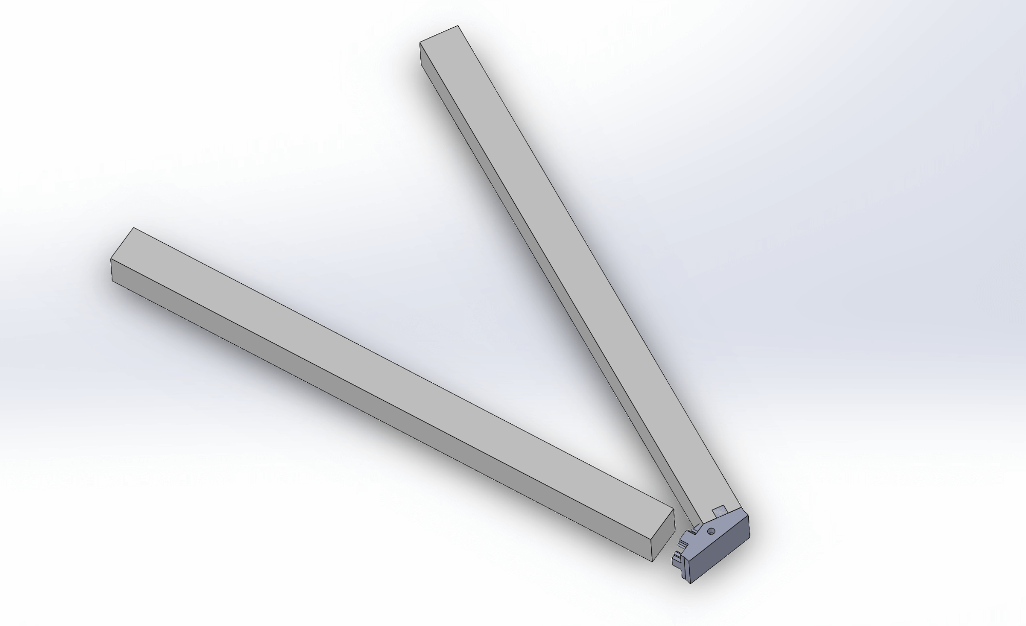
- Assembly
- Parts
- Push the two extrusions on the adapter. This might take some force. The side where the hole is small is UP.
- 2 x 300mm aluminium extrusion
- b3_2020adapter
¶ Alu front corners
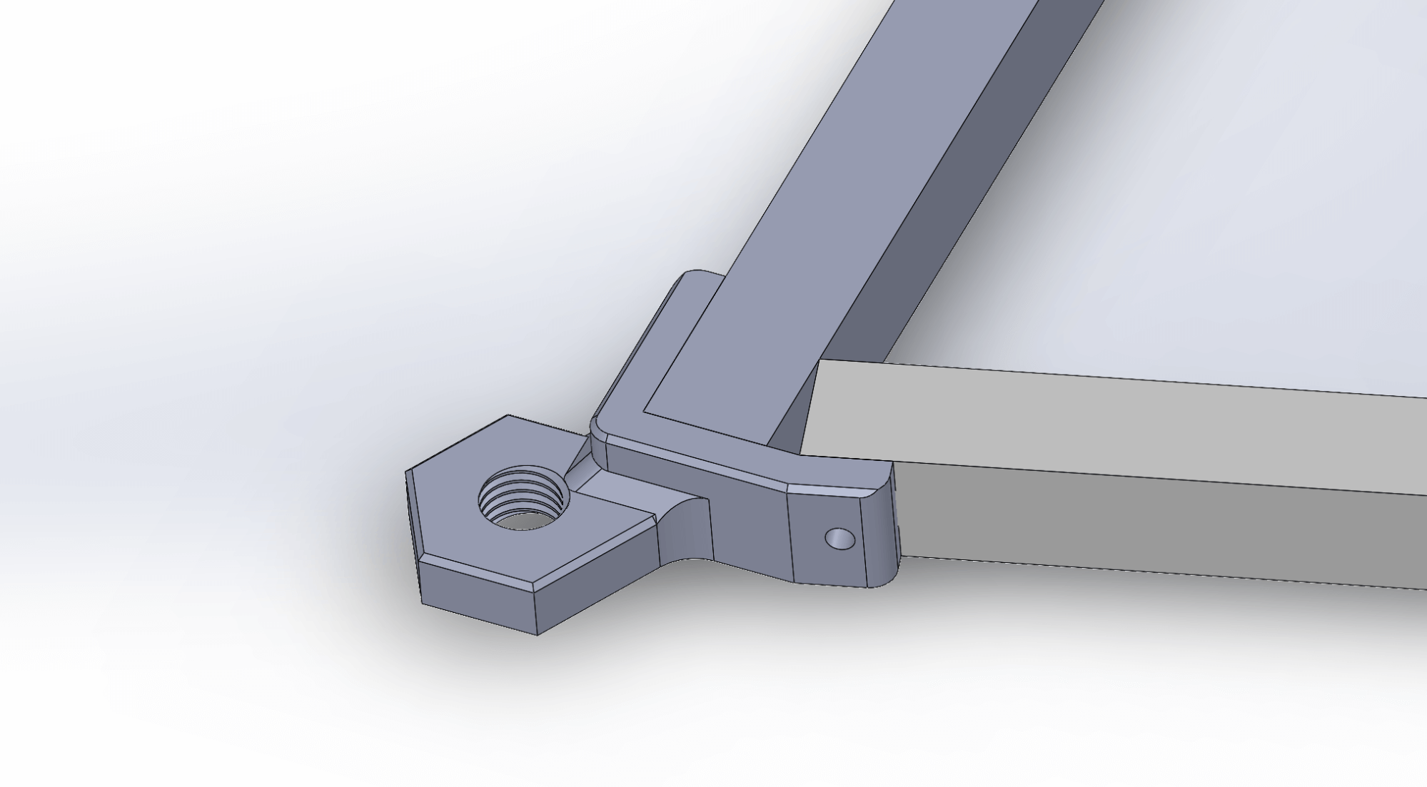
- Assembly
- Parts
- Hint
- Use the
M14_mount_right_2020baseandM14_mount_left_2020baseparts together with the extrusions to form a triangle. - Dont screw the screws in tight yet, this is just to make sure the profiles are aligned properly.
- 200mm aluminium extrusion
- M14_mount_left_2020base
- M14_mount_right_2020base
- 6 x M4x12
- 6 x T-nuts
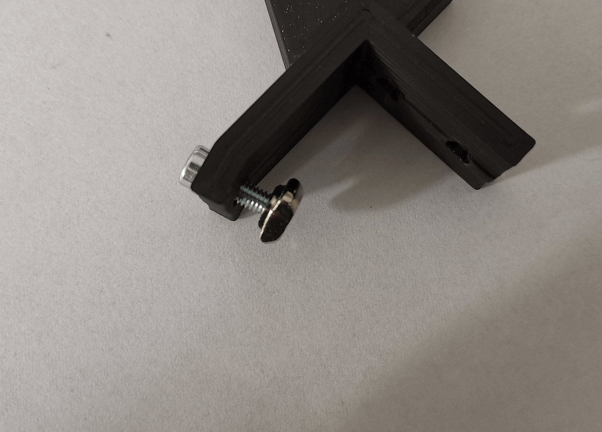
- Insert M4 screws into the part first, then attach the t nut, then insert into the aluminium extrusion and screw tight.
¶ Front corner stabilizer
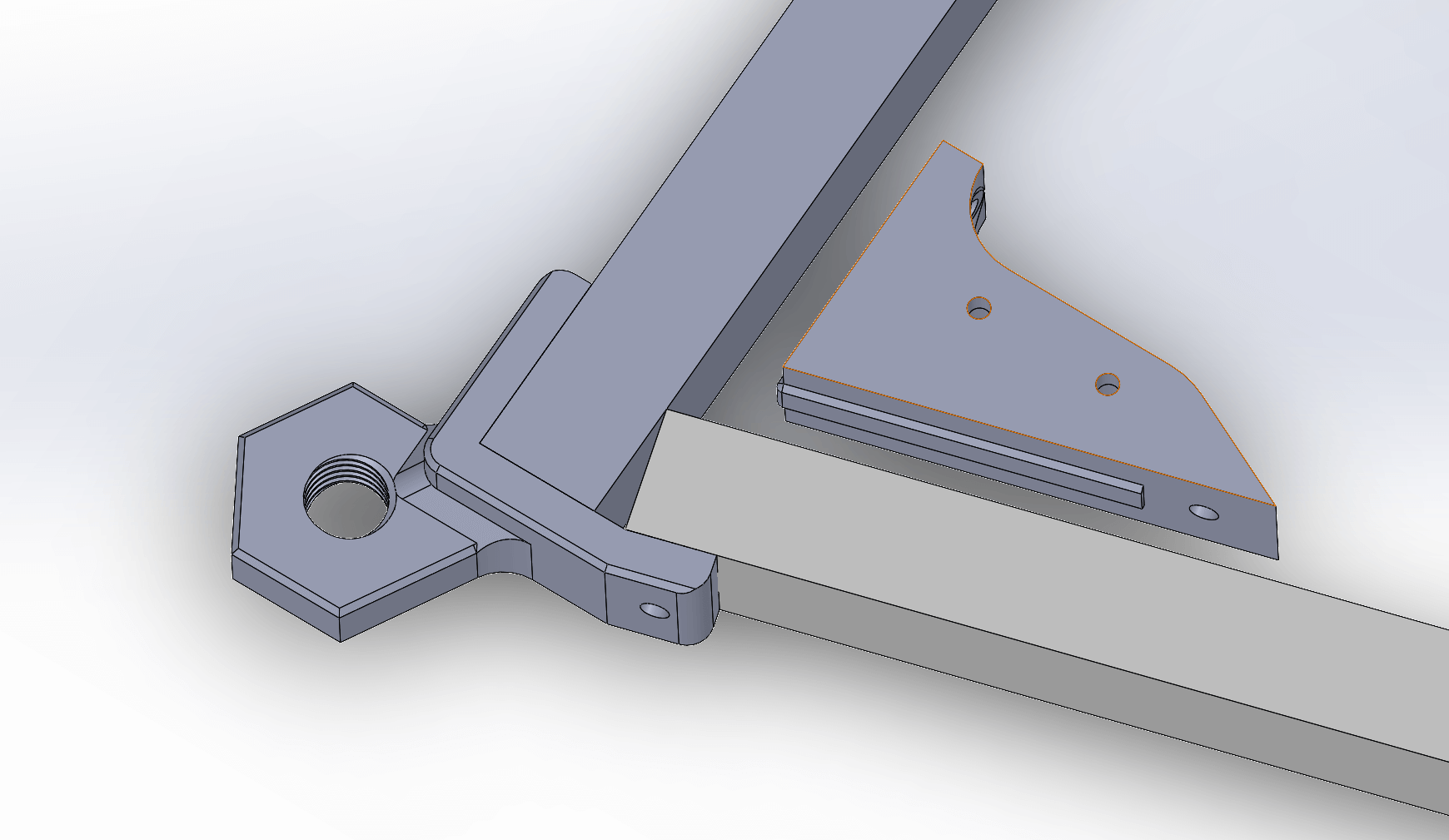
- Assembly
- Parts
- Take the connector and screw it tight. The side where the holes are small is UP.
- Repeat for the opposite side.
- b1_connector_right
- b1_connector_left
- 4 x M4x12
- 4 x T-nuts
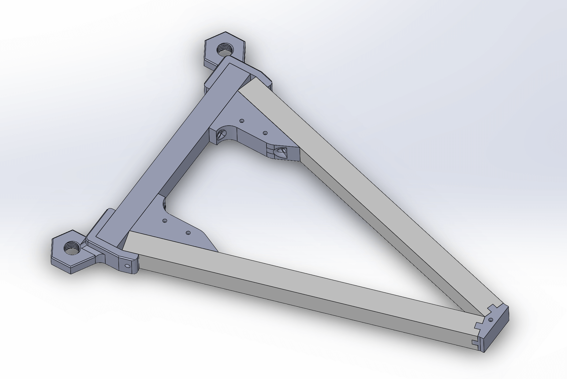
- Assembly
- Screw the M14 screws tight.
- The result should look like on the picture.
¶ Front rollmounts
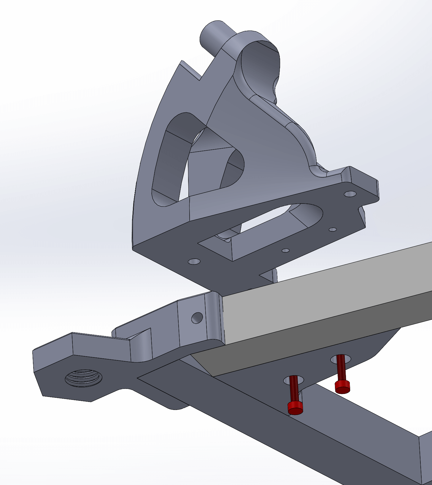
- Assembly
- Parts
- Insert the M3 screws on the bottom
- Screw the Rollmount on to orient it right.
- Take M4 screws and screw the Rollmount to the aluminium extrusion.
- 04_rollmount_2020base left (angle version according to your latitude)
- 04_rollmount_2020base right (angle version according to your latitude)
- 4 x M3x12
- 6 x M4x12
- 6 x T-nuts
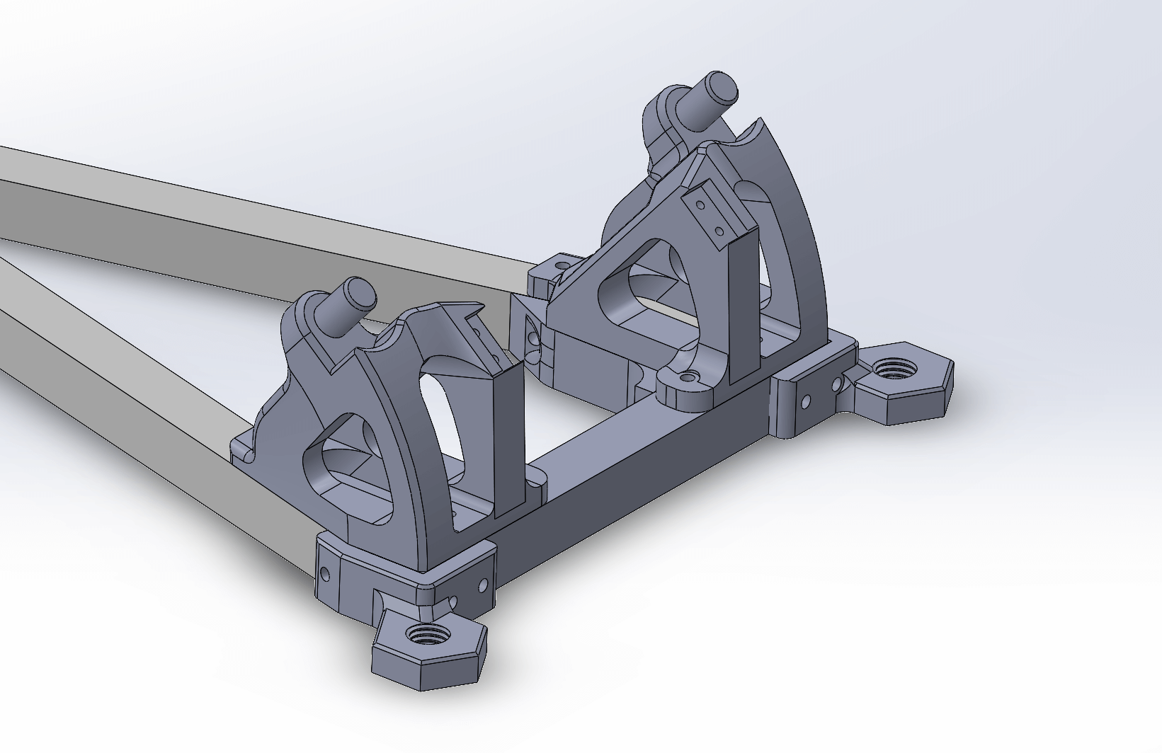
- Result
- Your Rollmounts may look different depending on the latitude version you're using.
¶ Rear rotation base
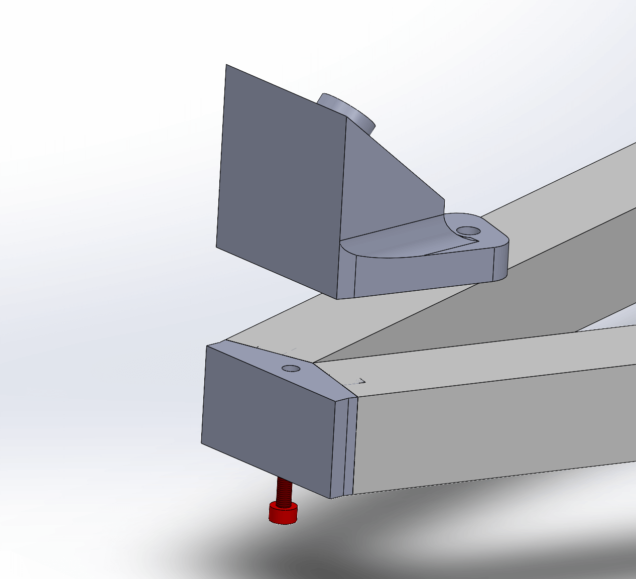
- Assembly
- Parts
- Screw the M3 screw from the bottom first, then use the M4 and t nuts.
- 02_angle_2020base (angle version according to your latitude)
- 1 x M3x12
- 2 x M4x12
- 2 x T-nuts
¶ Level holder
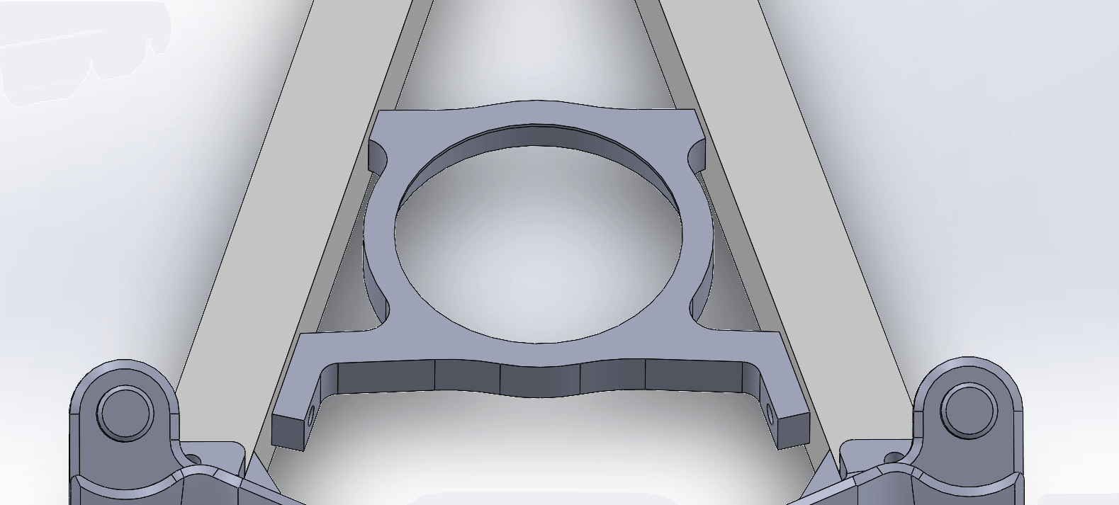
- Assembly
- Parts
- Insert the M4 screws and T-Nuts into the level holder.
- Slide the holder, with the inside ridge on top, into the 2020 extrusions.
- Tighten the screws.
- b2_level holder
- 2 x M4x12
- 2 x T-nuts
¶ Spirit level
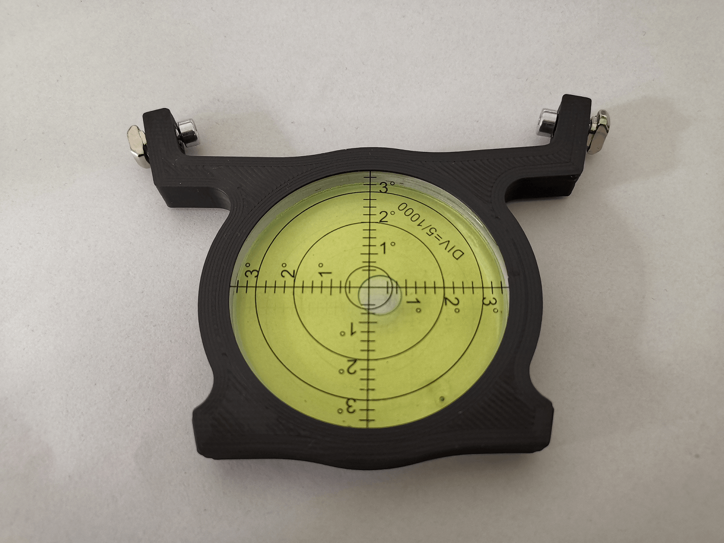
- Assembly
- Insert the bubble level from the bottom side.
¶ Rear corner
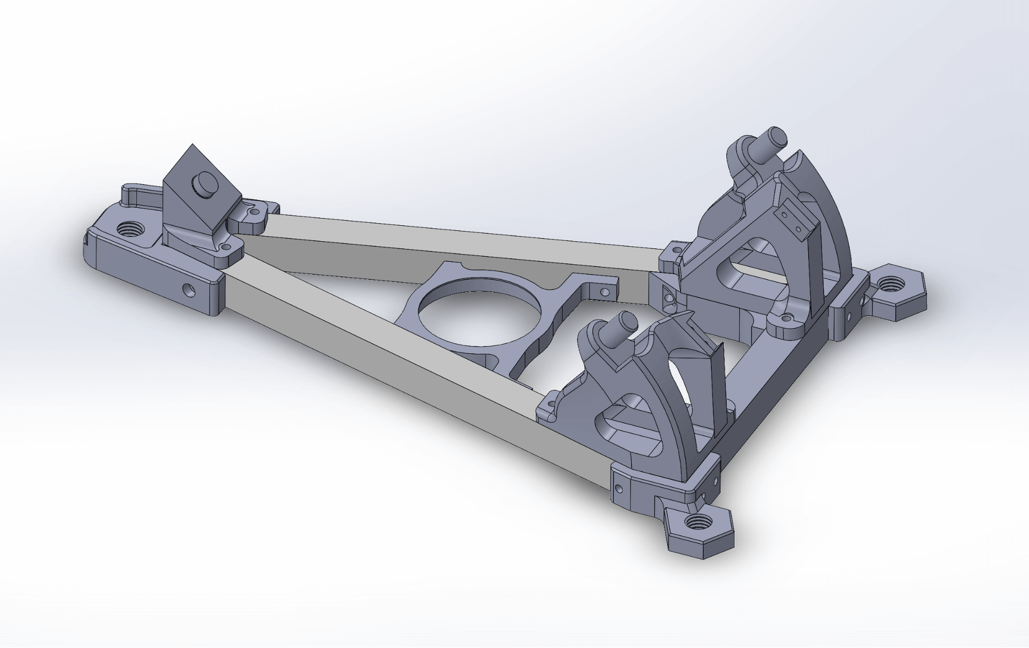
- Assembly
- Parts
- Attach the
M14_mount_rear_2020baserear corner with M4 bolts and T-nuts like you did the front corners. - The base is now complete and should look like illustrated.
- M14_mount_rear_2020base
- 2 x M4x12
- 2 x T-nuts
¶ DEC motor mount
The DEC motor moves the DEC ring and thus the camera adjusting the declination. Currently there are 2 types of DEC motors supported. Follow the steps corresponding to your motor type (and ignore the other).
¶ 28byj-48 stepper
There are two types of pulleys we currently support: the printed pulleys (20 teeth) and purchased pulleys (16 teeth).
¶ Printed pulley
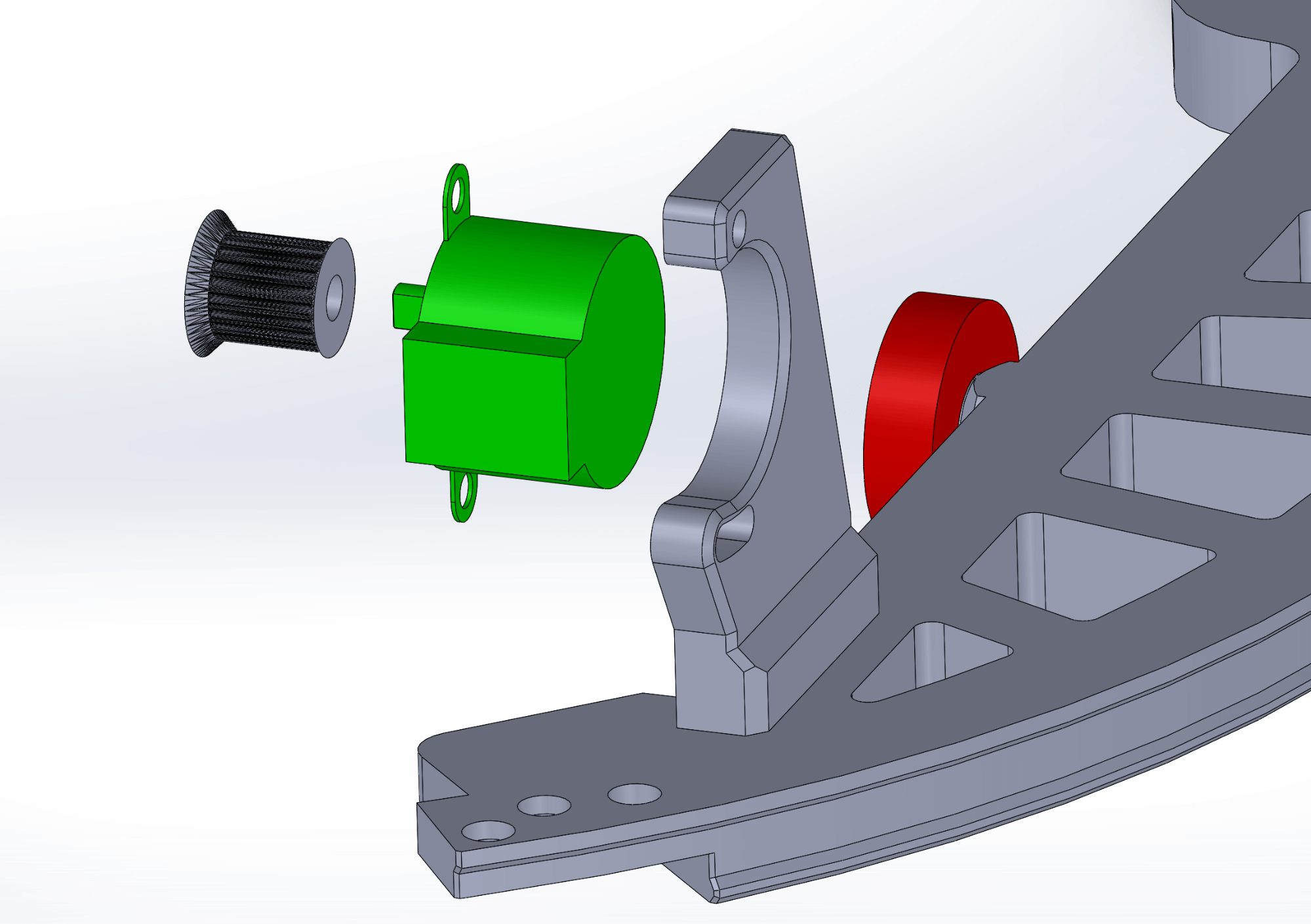
- Assembly
- Parts
- Attach the motor mount to the RA split ring part as demonstrated by using 3 x M3 screws.
- Put the pulley onto the stepper motor. The notch of the motor shaft should match the one of the printed pulley.
- Attach the stepper to the motor mount by using two M4 screws and tightening them on the other side with M4 nuts.
- 28byj-48 stepper
- 06a_splitring_part1
- 11_DEC_motor_mount
- 15_Pulley_GT2
- 3 x M3x12
- 2 x M4x12
- 2 x M4 nuts
¶ Purchased pulley
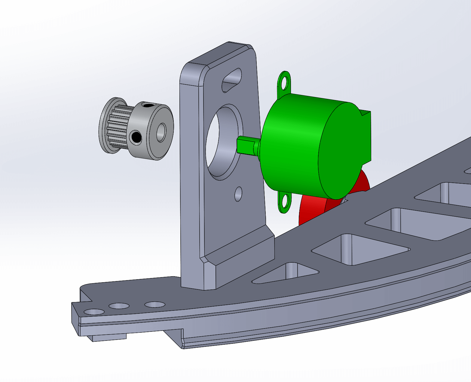
- Assembly
- Parts
- Attach the motor mount to the RA split ring part as demonstrated by using 3 x M3 screws.
- Put the pulley onto the stepper motor and tighten it by using two screws integrated into the pulley.
- Attach the stepper to the motor mount by using two M4 screws and tightening them on the other side with M4 nuts.
- 28byj-48 stepper
- 06a_splitring_part1
- 11_DEC_motor_mount_low
- GT2 pulley
- 3 x M3x12
- 2 x M4x12
- 2 x M4 nuts
¶ Nema stepper
We assume that you use purchased pulley with the nema steppers.
¶ Round NEMA 14 stepper
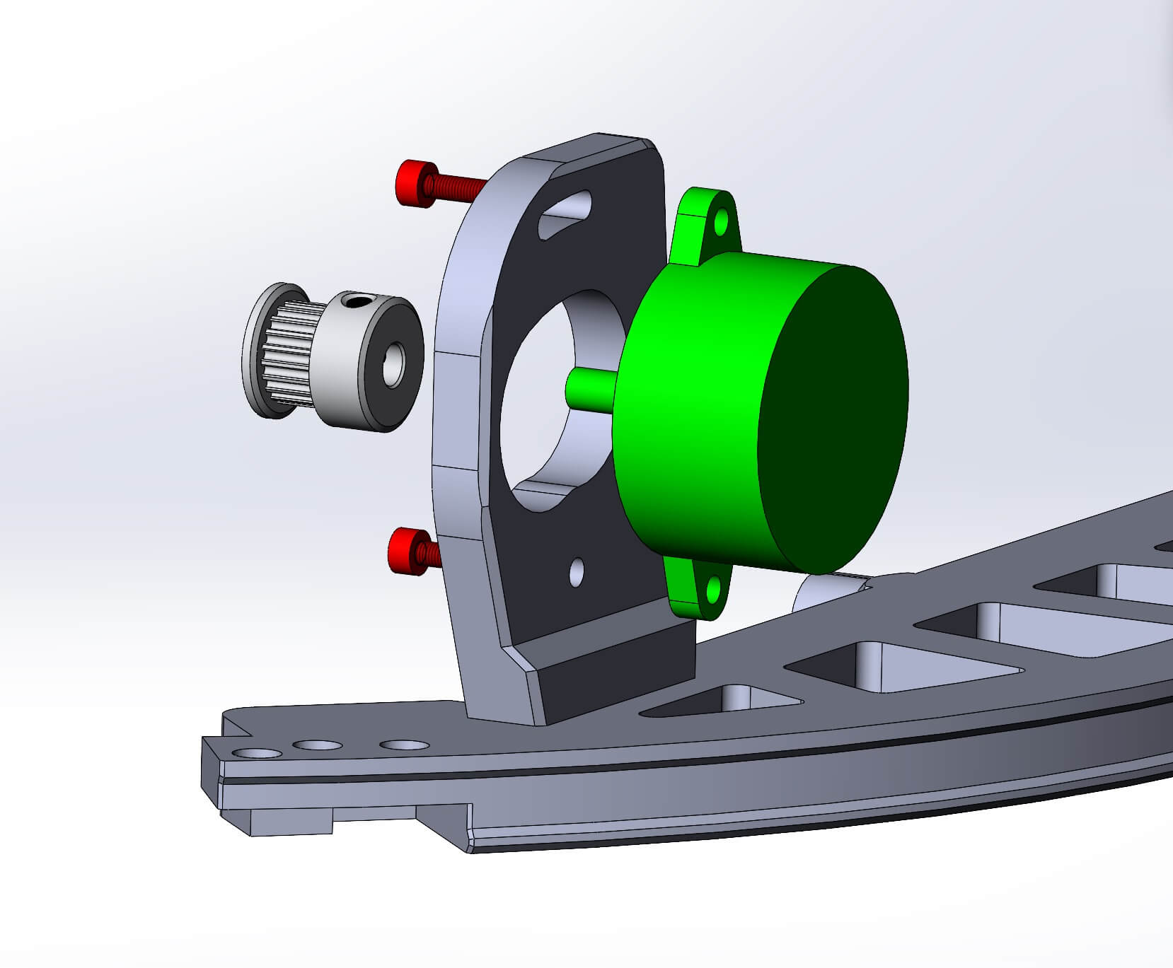
- Assembly
- Parts
- Attach the motor mount to the '06a_splitring_part1' part as demonstrated by using 3 x M3 screws.
- Put the pulley onto the stepper motor and tighten it by using two screws integrated into the pulley.
- Attach the stepper to the motor mount by using two M3 screws.
- Round NEMA 14 stepper
- 06a_splitring_part1
- 11_DEC_motor_mount_v9_NEMA
- GT2 pulley
- 5 x M3x12
¶ Square NEMA 17 stepper
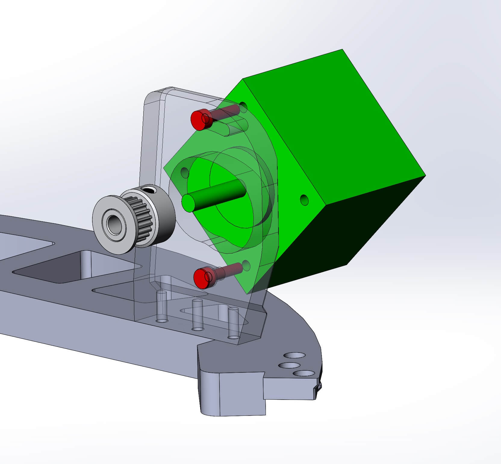
- Assembly
- Parts
- Attach the motor mount to the '06a_splitring_part1' part as demonstrated by using 3 x M3 screws.
- Put the pulley onto the stepper motor and tighten it by using two screws integrated into the pulley.
- Attach the stepper to the motor mount by using two M3 screws.
- Square NEMA 17 stepper
- 06a_splitring_part1
- 11_DEC_motor_mount_v9_NEMA
- GT2 pulley
- 5 x M3x12
¶ RA ring
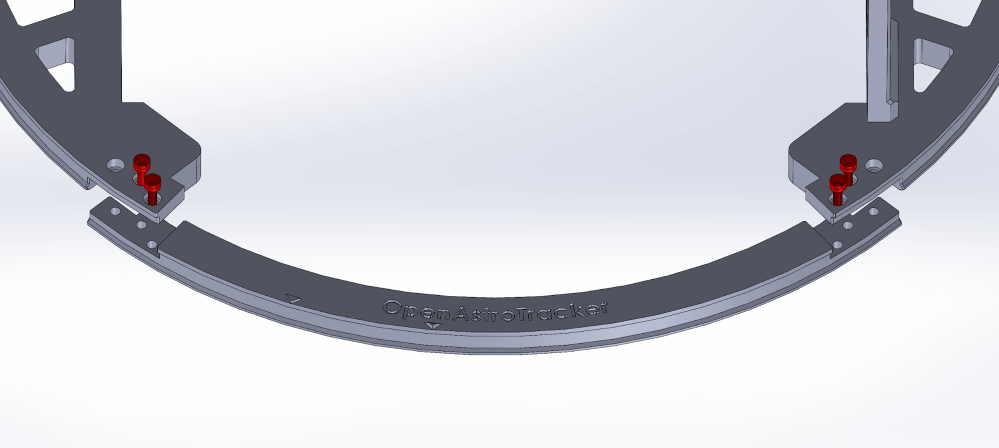
- Assembly
- Parts
- Only tighten these screws hand-tight. Overtightening will deform the ring.
- Third screw will be used in a later step.
- 06a_splitring_part1
- 06b_splitring_part2
- 06c_splitring_part3
- 4 x M3x12
- 4 x M3 nuts
¶ Camera mount
This is where your actual camera (and maybe the guide scope) will be attached to. It moves with both rings.
¶ L-holders
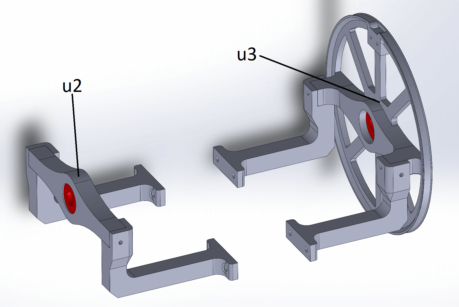
- Assembly
- Parts
- Push the two bearings into the parts “u2” and “u3”.
- Attach the 4 “L-holders” with two M3x12 screws each. They will only fit in one way, the slightly shorter ones go on the side of the DEC wheel.
- u3_drivedisc_DEC_unimount
- u1_Lholder_left_back
- u1_Lholder_left_front
- u1_Lholder_right_back
- u1_Lholder_right_front
- u2_bearing_holder
- 8 x M3x12
¶ 2020 Extrusion
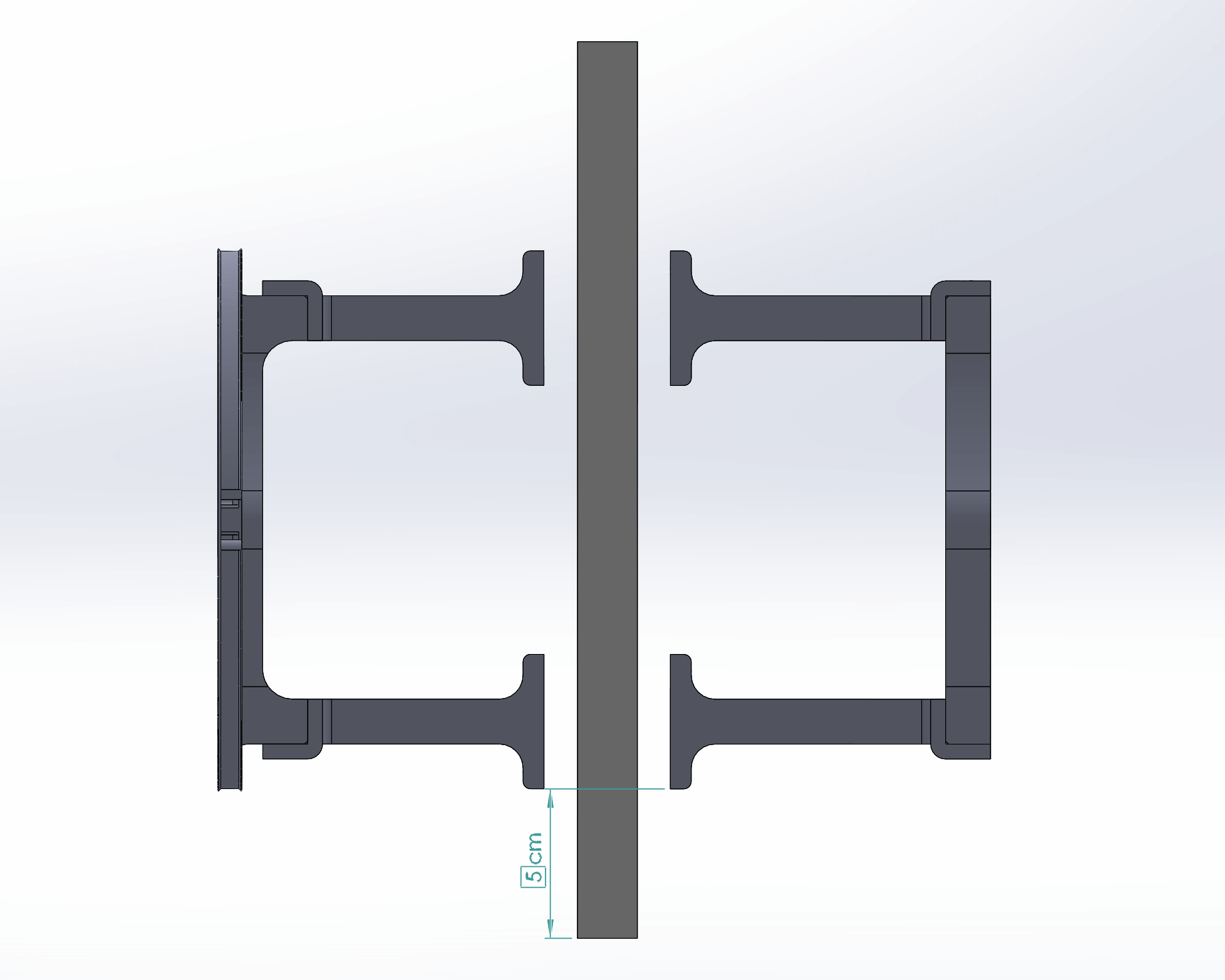
- Assembly
- Parts
- Connect the two parts to the 2020 profile with 8 T nuts and 8 M4x12 screws.
- Let the profile stand out about 5cm towards the backside (take the DEC ring position as reference in the illustration).
- 300mm 2020 extrusion
- 8 x M4x12
- 8 x M4 T-nuts
¶ RA + DEC + camera mount
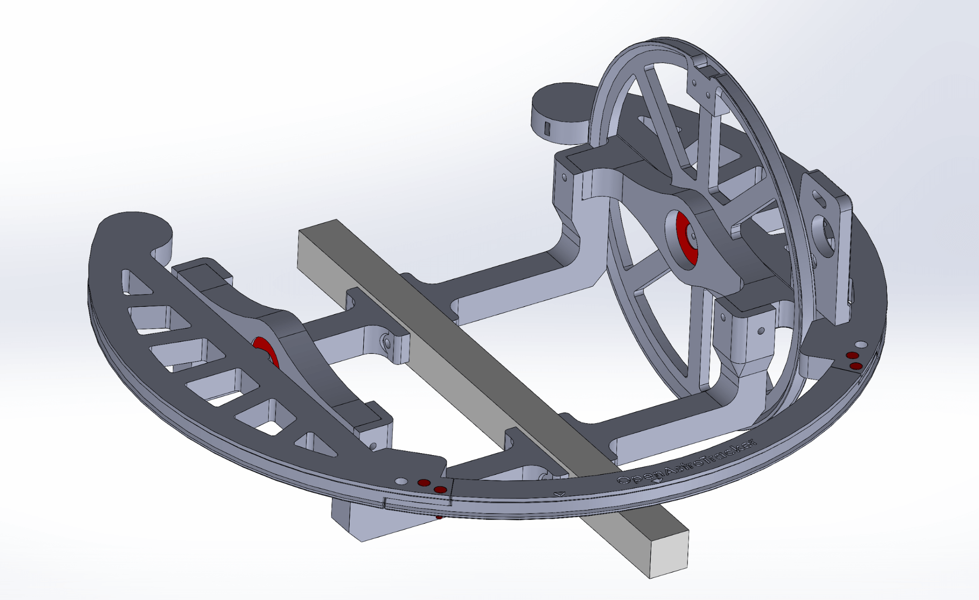
- Assembly
- Put the camera mount assembly into the RA ring.
¶ Holder
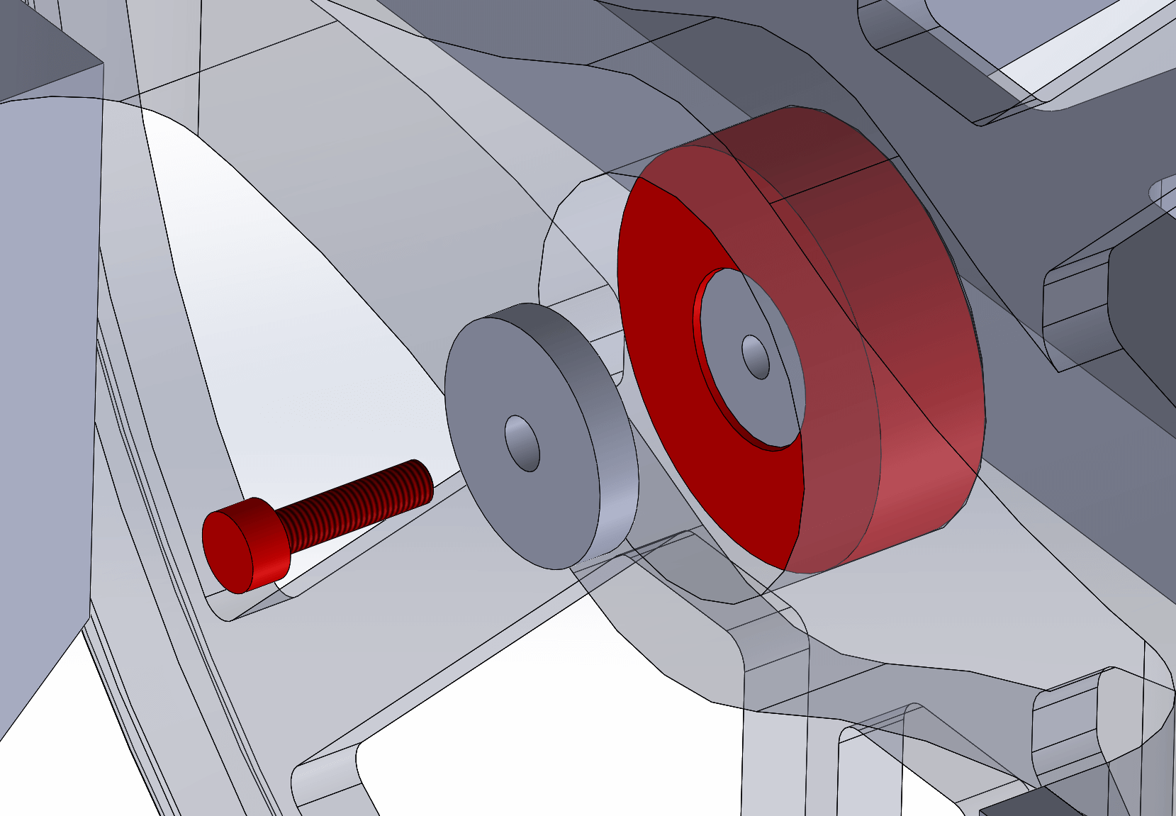
- Assembly
- Parts
- Secure both sides with the
u4_holderand a M3x12 screw.
- 2 x u4_holder
- 2 x M3x12
¶ Poles
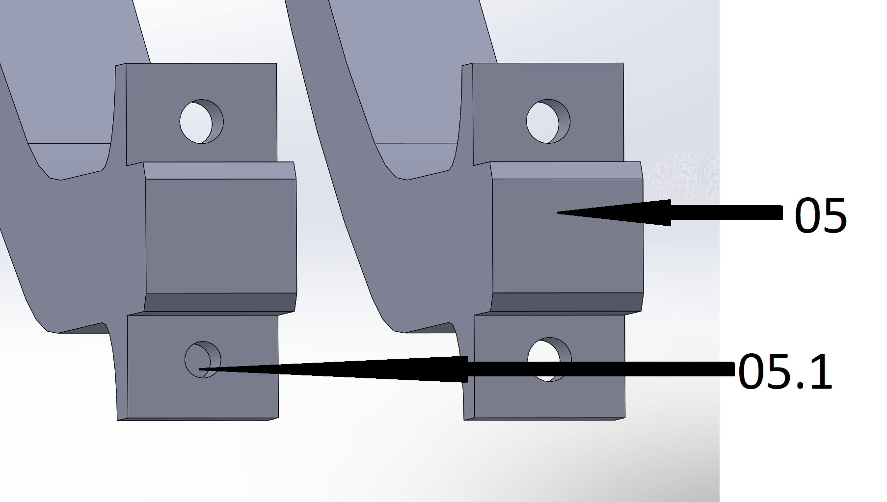
- Info
- Parts
- The parts 05 and 05.1 are very similar.
- One of the holes is filled on part 05.1 (as shown)
- Part 05 has 3 holes to mount part 05.2.
- 2 x 05_pole
- 2 x 05.1_pole
¶ Insert poles
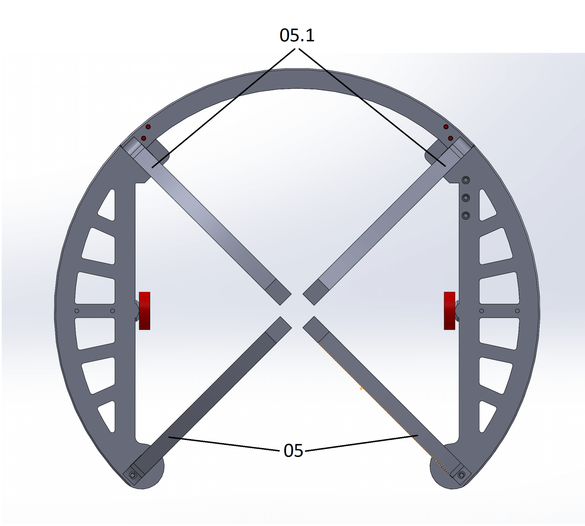
- Info
- Parts
- Insert the 4 poles on the fitting holes and push them all the way in. If they are loose, take 4 M3 screws and screw them into the holes on the inside.
- 2 x 05_pole
- 2 x 05.1_pole
¶ Bottom side
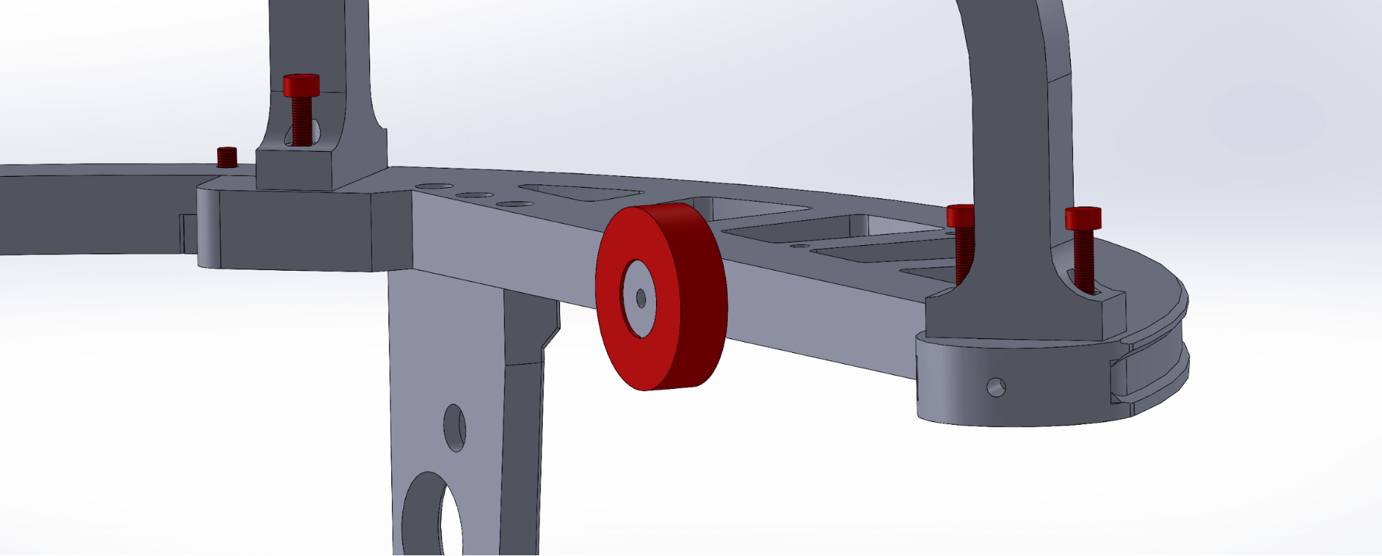
- Info
- Parts
- Screw in the poles with 3 x M3 screws on the bottom of RA ring.
- Front poles need 1 screw each
- Rear poles need 2 screws each
- 2 x 05_pole
- 2 x 05.1_pole
- 6 x M3x12
¶ Top side
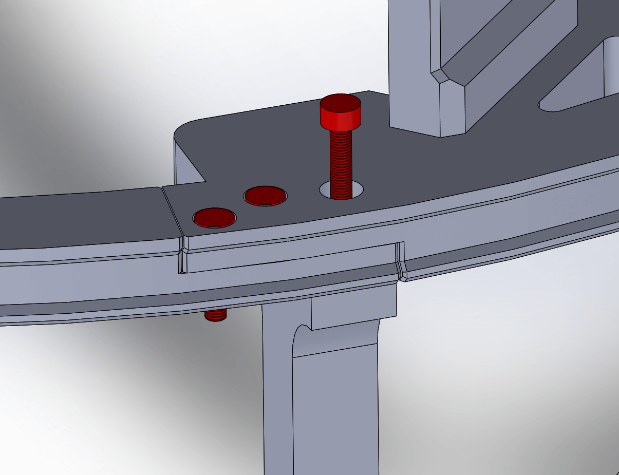
- Info
- Parts
- Use the free holes on the RA ring to secure the front poles to the ring on the top side.
- 2 x M3x12
¶ Base + camera mount
You are nearly there.
¶ Polemount
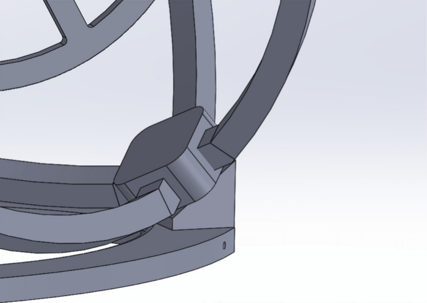
- Info
- Parts
- Put the bearing into the polemount.
- Push the RA poles into the polemount.
- Put the assembled ring on the base.
- 03_polemount_6801
- 6801 bearing
¶ Front bearings
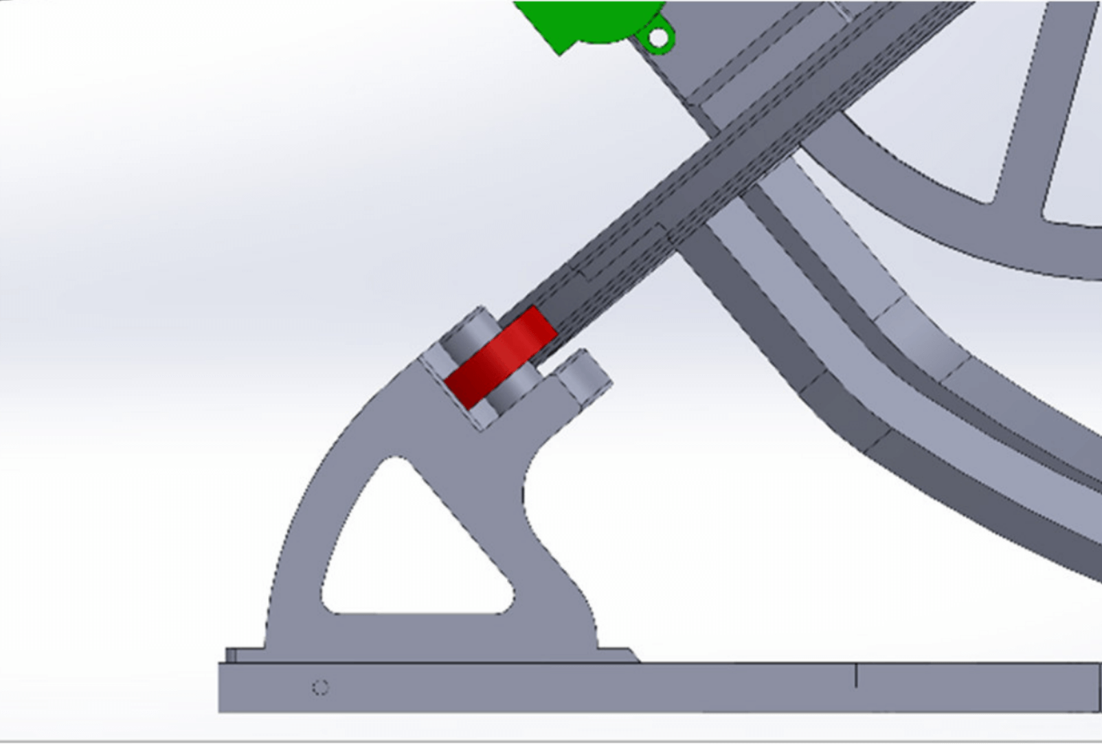
- Info
- Parts
- Adjust the bearings so the ring rests on them.
- 2 x 6001 bearings
¶ Stabilizer
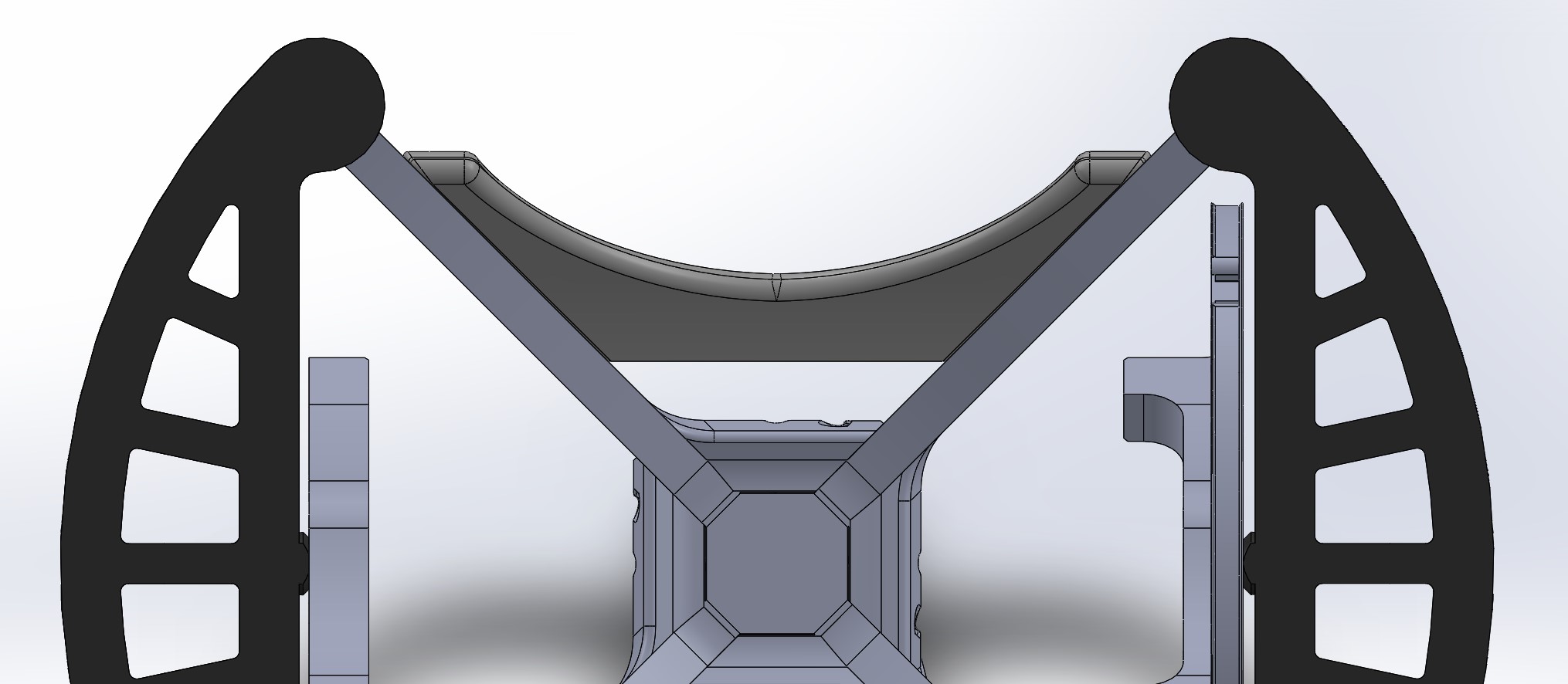
- Info
- Parts
- Attach the stabilizer to the rear two poles by using 3 M3 screws on each side of it.
- 05.2_stabilizer
- 6 x M3x12
¶ RA motor
Like for DEC axis there are two motor types supported.
¶ 28byj-48 stepper
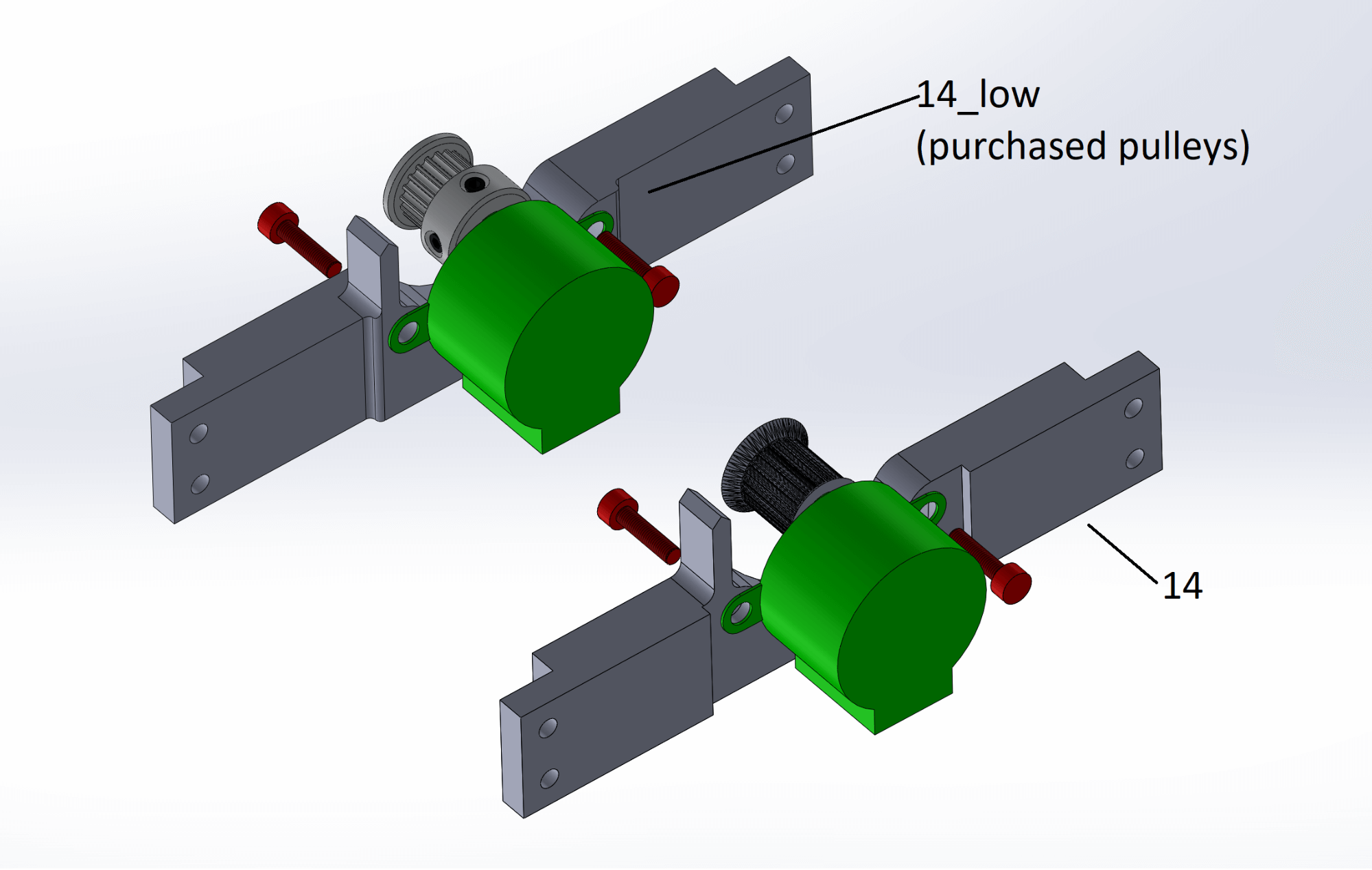
- Info
- Parts
- Insert screws as illustrated from different sides, to allow easier adjustment of the belt tension.
- 14_RA_motor_mount (printed pulley) OR 14_RA_motor_mount_low (purchased pulley)
- 15_Pulley_GT2 (printed) OR purchased GT2 pulley
- 28byj-48 stepper motor
- 2 x M4x12
- 2 x M4 nut
¶ Nema stepper
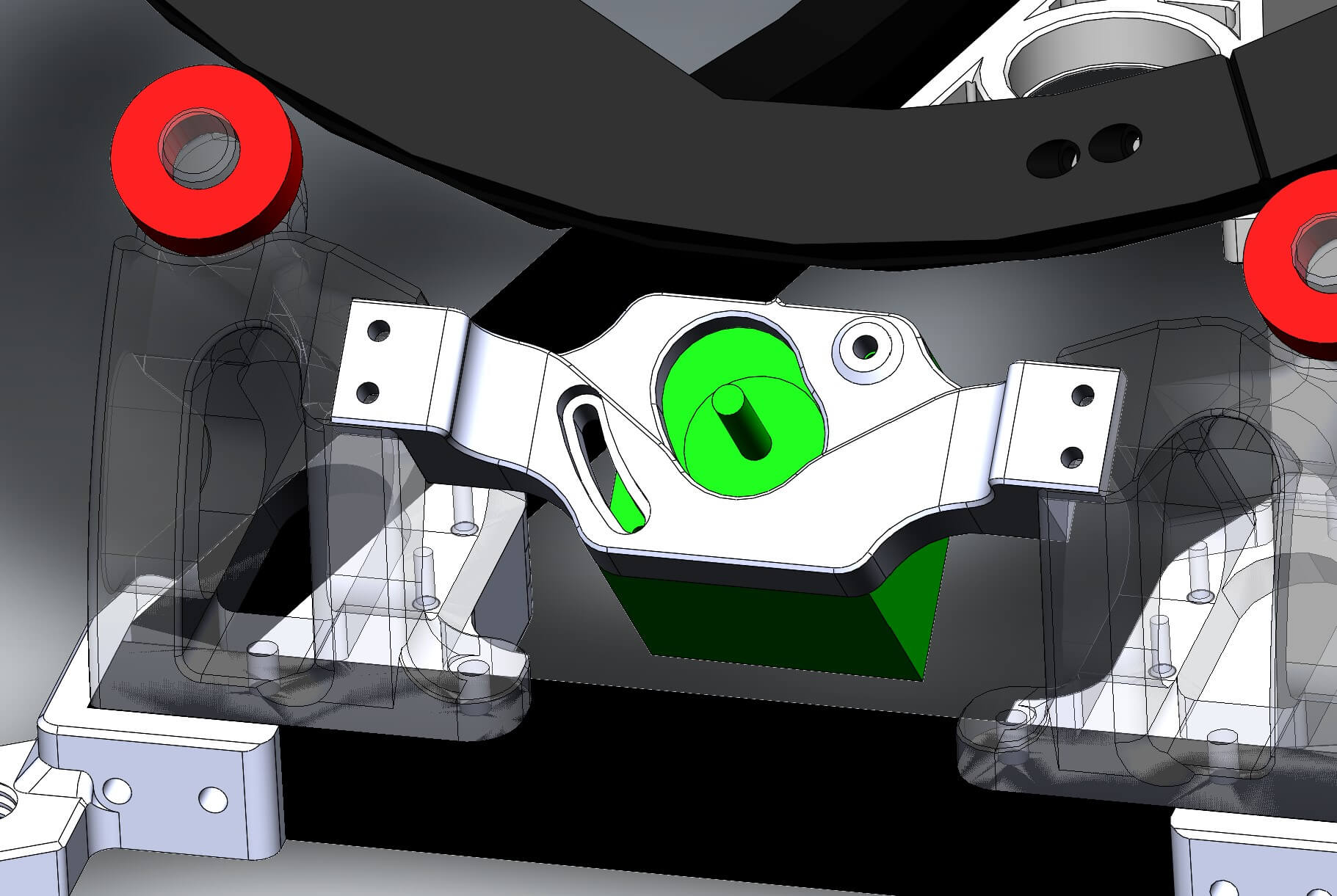
- Info
- Parts
- Attach the motor to the motor mount by using two M3x12 and two M3x8 screws
- Attach the motor mount to the base by using four M3x12 screws
- 14_RAmotor_mount_NEMA_down
- 6 x M3x12
¶ Belt
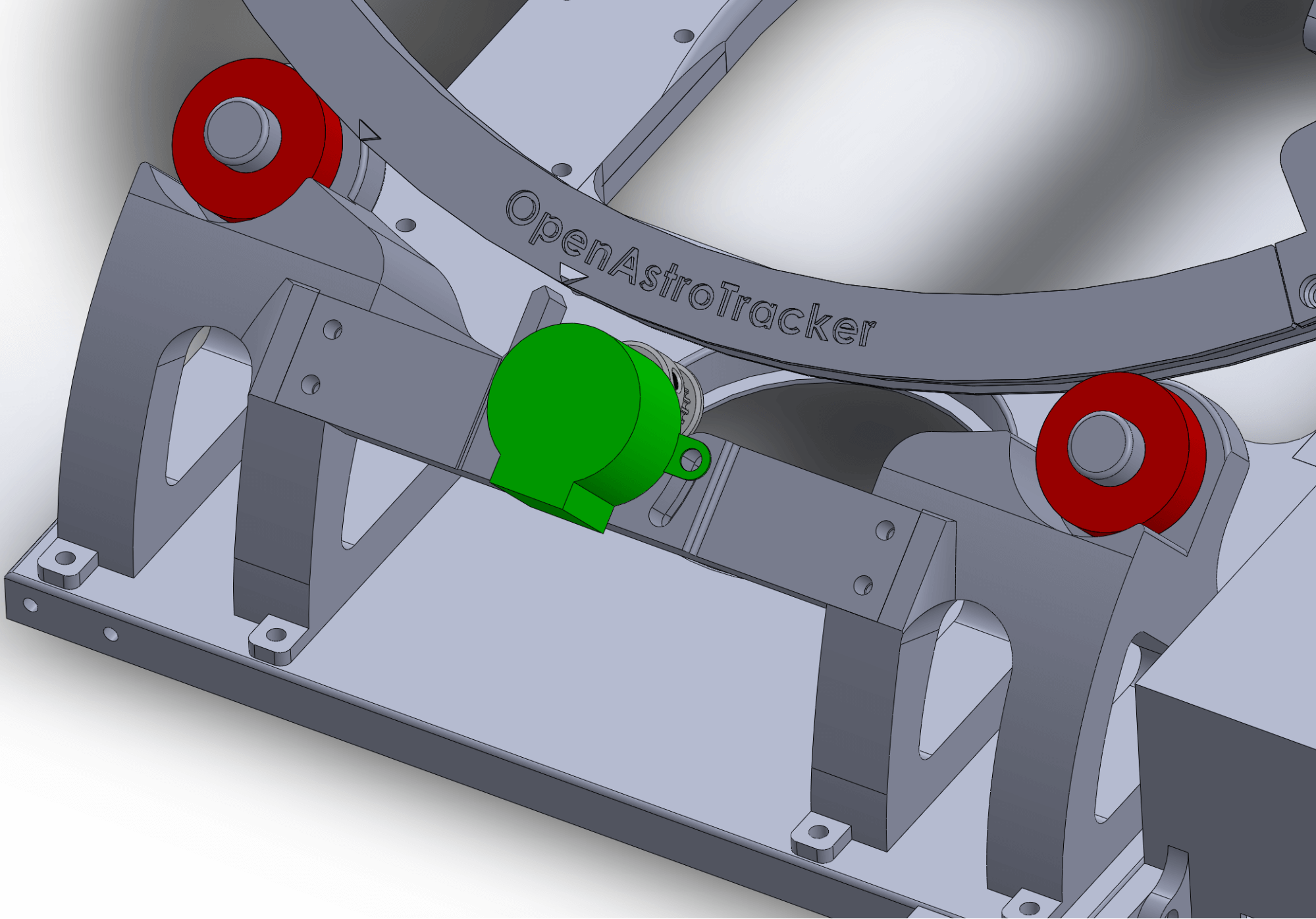
- Info
- Parts
- Take a timing belt and move it around the ring,
- Fasten it on the top of the ring with the M3 screws.
- Make sure it has a nice tension but don’t overtighten it.
- timing belt
The RA motor mount has a indicator that lines up with the “home” and “1 hour” points on the ring. The home point is the larger one, if it is lines up it means the ring is centered.