This page is outdated and kept for archive reference only. It is no longer applicable to the latest version of the OAT.
For the latest method of using an Arduino Mega board using a RAMPS shield, see here.
¶ General
The Arduino Mega 2560 supports all features of the OAT. It allows the most customization, however requires external stepper driver boards for all motor types.
¶ Features
¶ Supported
- RA/DEC Motors using NEMA steppers (with external driver breakout boards)
- RA/DEC Motors using bipolar modified 28BYJ steppers (with external driver breakout boards)
- UART support
- AutoPA support using NEMA steppers (with external driver breakout boards)
- AutoPA support using bipolar modified 28BYJ steppers (with external driver breakout boards)
- AutoPA support using bipolar modified 28BYJ steppers (with external driver breakout boards)
- Arduino LCD shield with buttons
¶ Firmware
Choose the Mega 2560 board in Configuration_local.hpp. Refer to the Constants.hpp file for the correct option.
¶ Wiring
¶ Motor Wiring
¶ Driver Breakout Board (NEMA Steppers and bipolar 28BYJ)
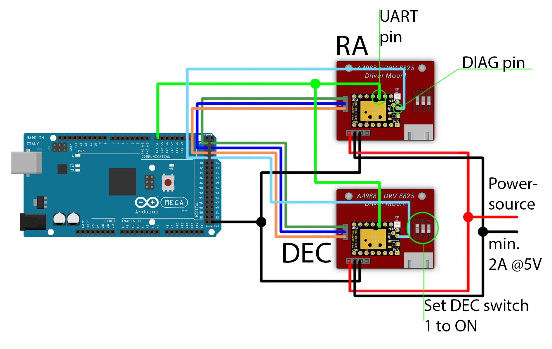
| Driver Pin | Arduino Pin | |
|---|---|---|
| RA Step | 22 | |
| RA Direction | 24 | |
| RA Enable | 26 | |
| RA UART | TX3 | |
| RA DIAG | 28 | (not needed) |
| DEC Step | 23 | |
| DEC Direction | 25 | |
| DEC Enable | 27 | |
| DEC UART | TX3 | |
| DEC DIAG | 29 | (not needed) |
For UART, the DEC driver board needs to have
MS1enabled, do this by switching the 1 button toON. All others, also on the RA driver have to beOFF
Be sure to have the Drivers Logic GND actually connected properly to Arduino GND. It HAS to be Arduino GND, it can not be the same GND as from the stepper powersource!
¶ CAT cables
With the standard wiring it is possible to transmit all signals for both TMC drivers over a single Ethernet cable. (If you want to use a different wiring option, check out other Enclosures).
Each driver needs the following wires: STEP, DIR, EN, UART, GND and DIAG if the autohoming feature is used (still in development). Ethernet cables have 8 wires, so we have to get a little bit creative to get the required connections into a single cable. The GND and UART wires for example can be shared by both drivers so we can save 2 wires by making a Y connection on the driver side. The EN wires do not necessarily need to be connected to the Arduino at all, all they need is to be driven with a logic LOW, that means we can just attach them to a GND connection. That saves another 2 wires.
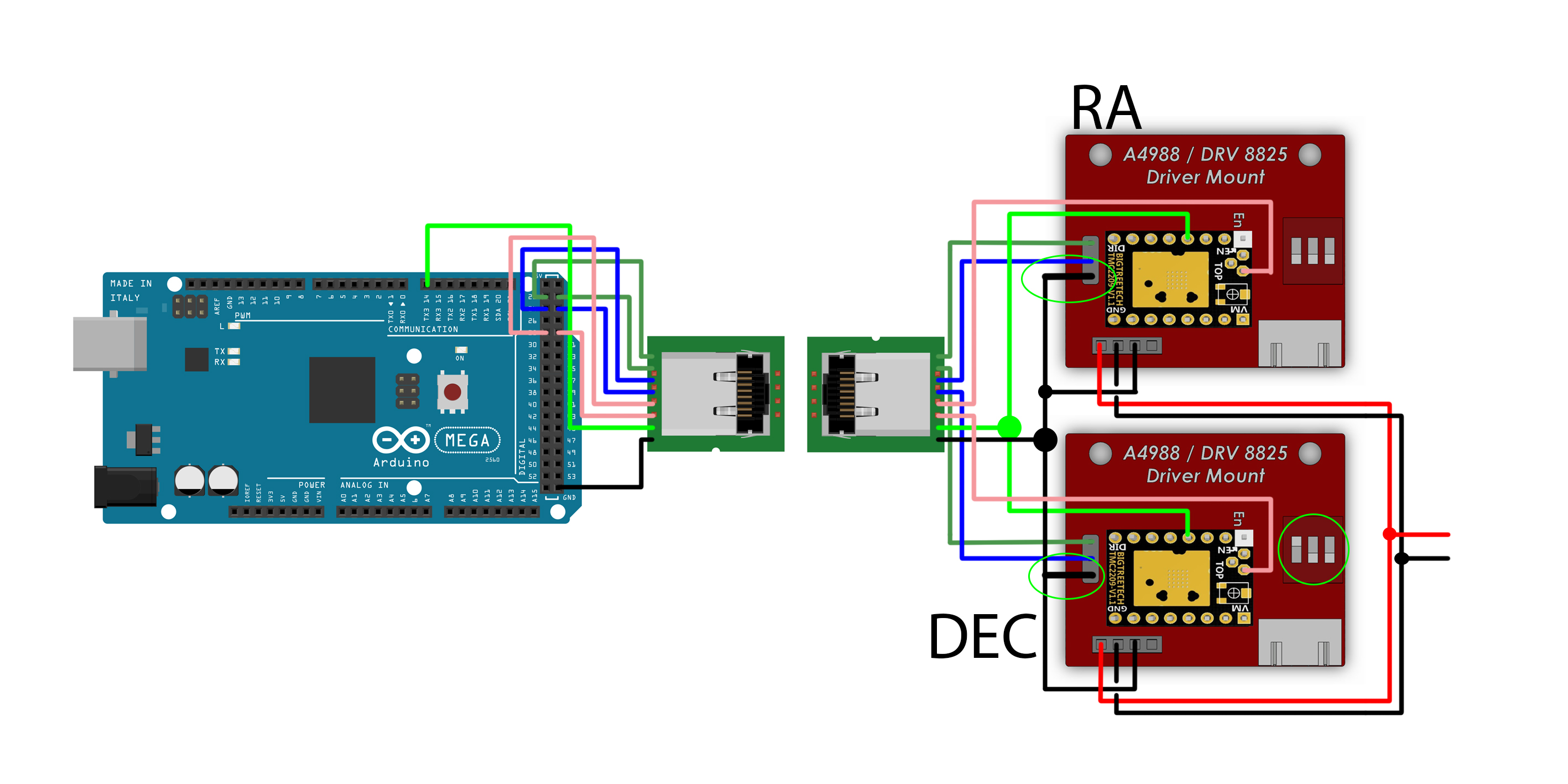
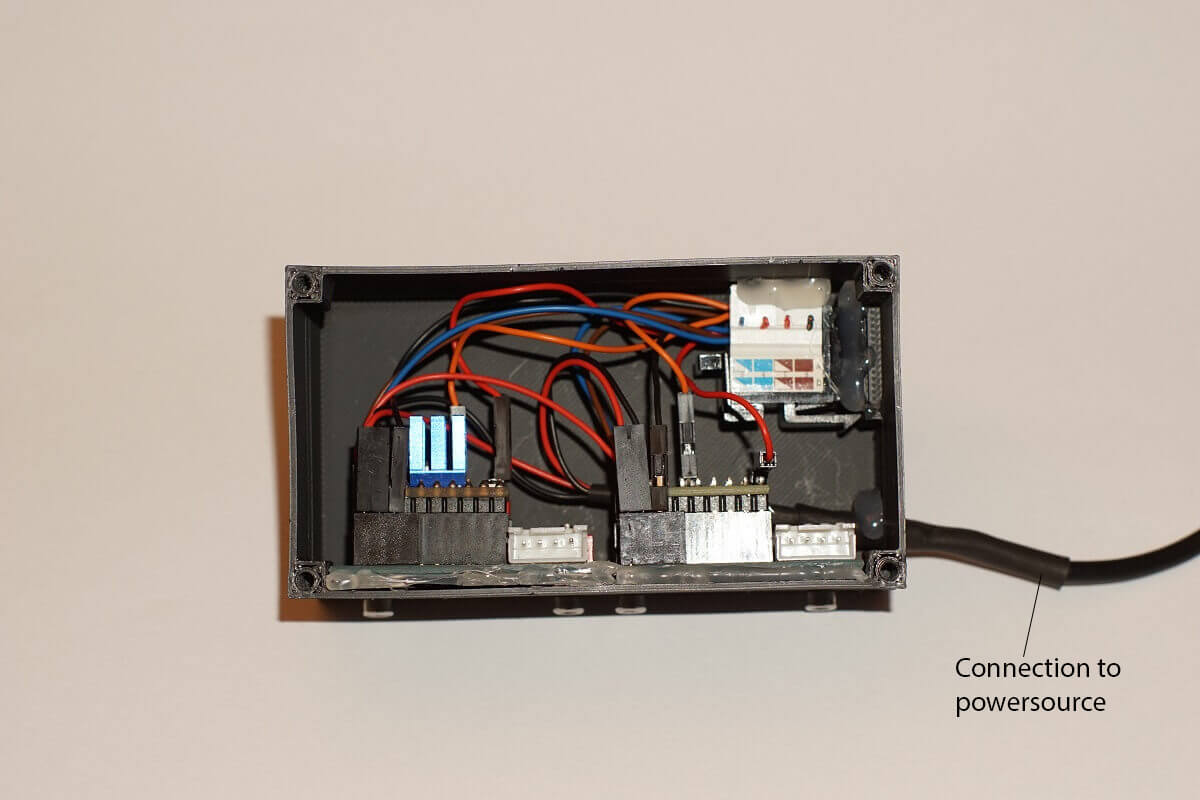
Note the EN pins on the driver side that are now connected to GND.
The easiest way to get a Y connection for GND and UART is to simply force two wires into a single connector.
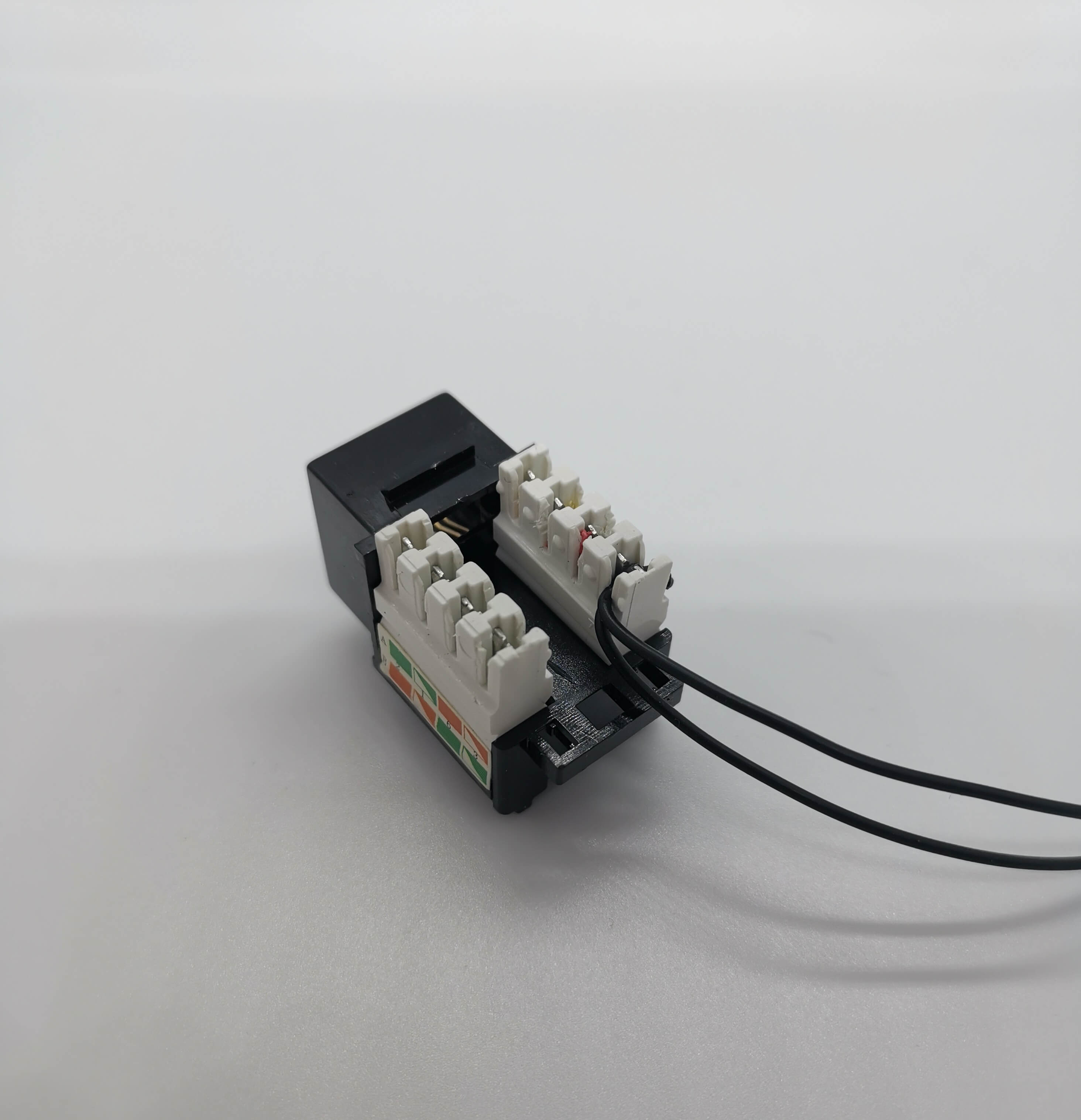
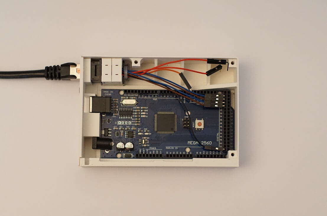
To not get confused later, it helps a lot to colorcode your connections and write them down. The side of the CAT6 adapter will have some numbers on it. For example write down: Slot 1, Blue, RA STEP. This will help a lot when you do the other side.
The pins can be changed in the configuration_pins.hpp, but the default wiring is:
- 1 x GND: Arduino GND
- 2 x RA/DEC STEP: 22/23
- 2 x RA/DEC DIR: 24/25
- 1 x UART: Tx3
- 2 x RA/DEC DIAG: 28/29 (not needed)
As you can see in the image, bend pin connectors help a lot.
¶ UART Wiring
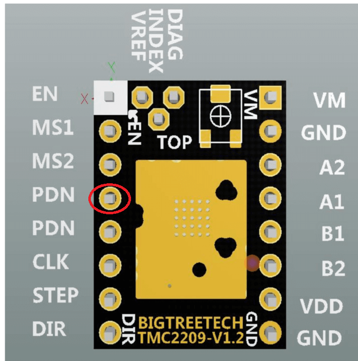
This pin will be used to configure the driver (microstepping, current etc.).
¶ Bigtreetech TMC2209
¶ Watterot TMC2209
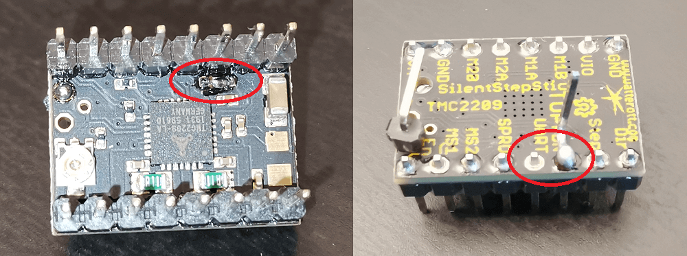
You will have to solder a bridge thats right beneath the two UART pins. It is 3 pads that all need a connection with each other. Then, solder a wire or pin on the top of the board to one of the UART pins.
¶ MKS TMC2209
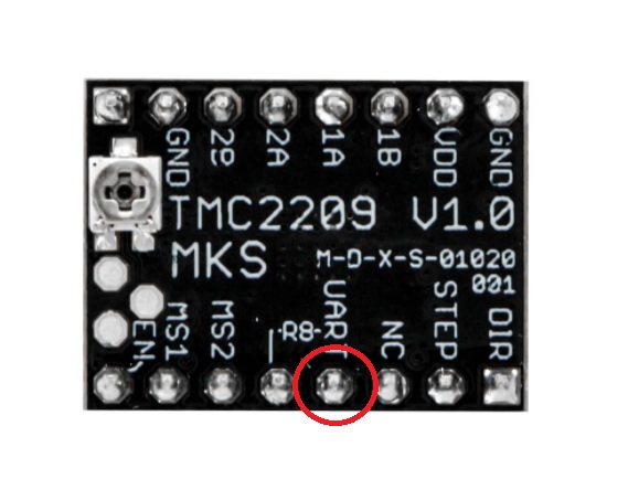
Like on the Watterot drivers, you will have to solder a pin or wire to the top of the board, to the marked pin. But you wont have to solder the bridge.
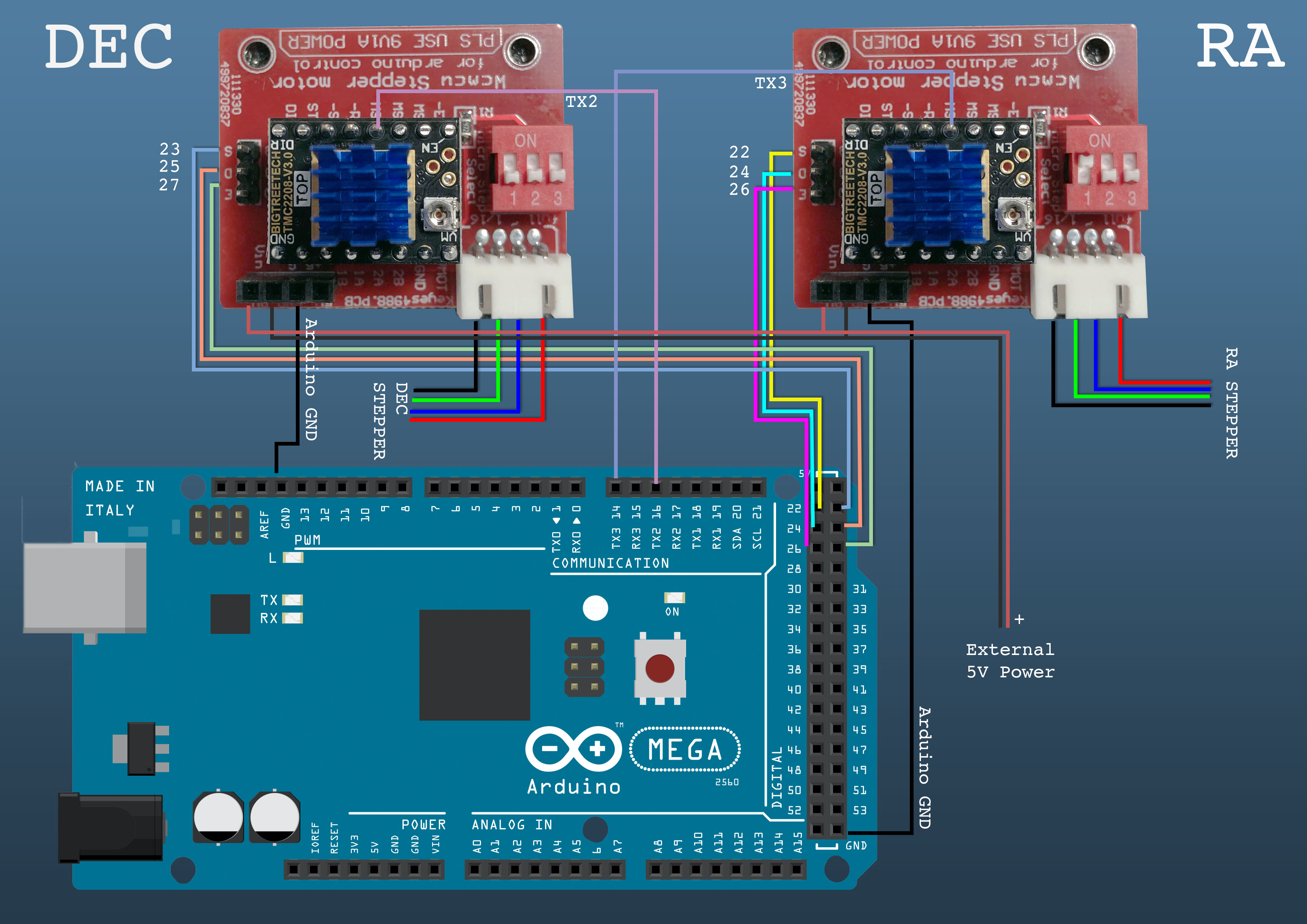
¶ TMC2208
The BigTreeTech TMC2208-v3.0 do support UART and 256 micro steps but there is a couple of things we need to change to get it to work. Also, make sure you get the ones with UART enabled from the factory unless you want to bridge them yourself.
Leave the MS Dips OFF on both boards.
- Connect DEC UART to TX2
- Connect RA UART to TX3
- In
Configuration_pins.hpp- Make the following changes
//DEC TMC2209 UART specific pins
#define DEC_SERIAL_PORT Serial2
#define DEC_DRIVER_ADDRESS 0b00
