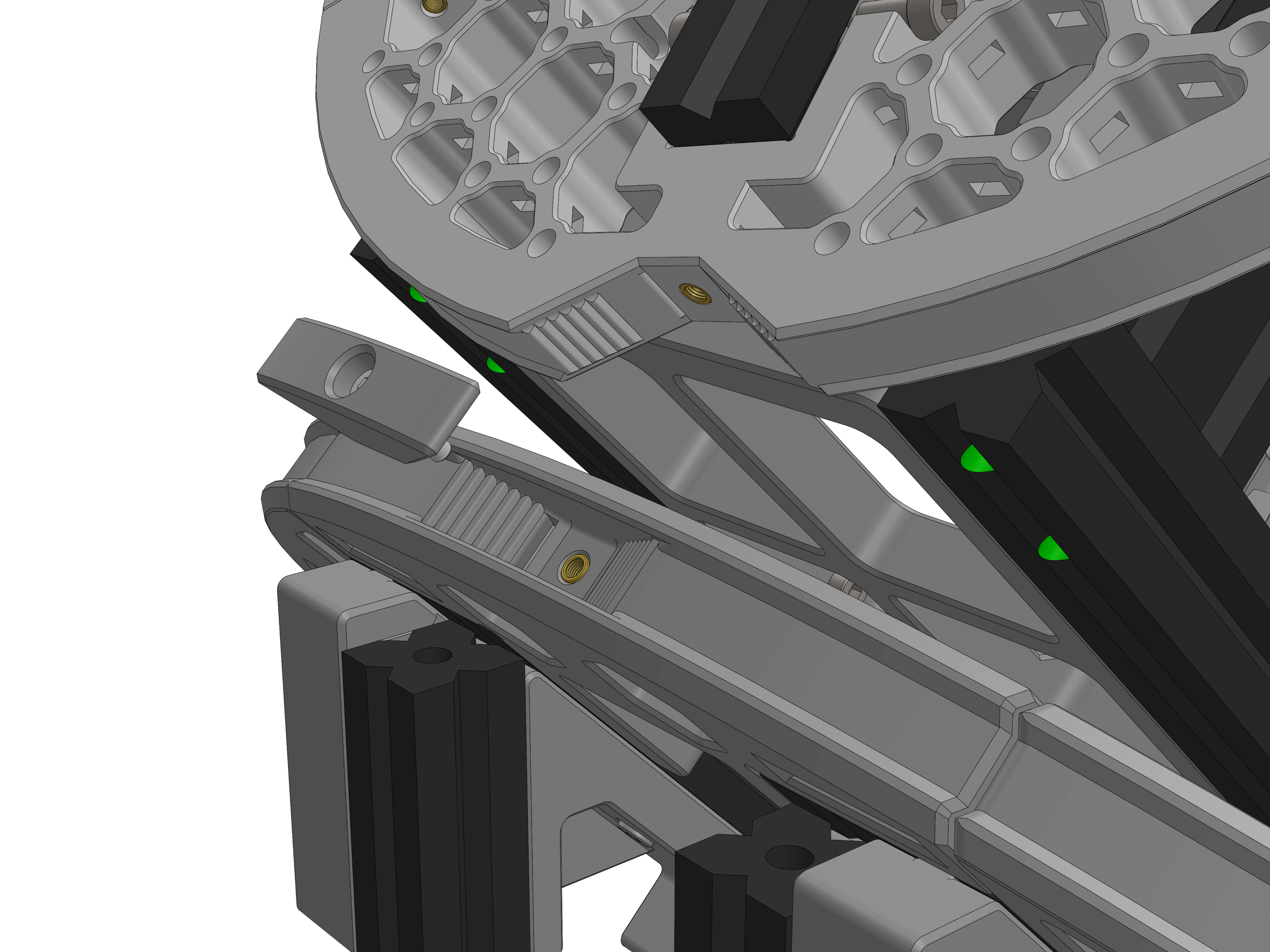
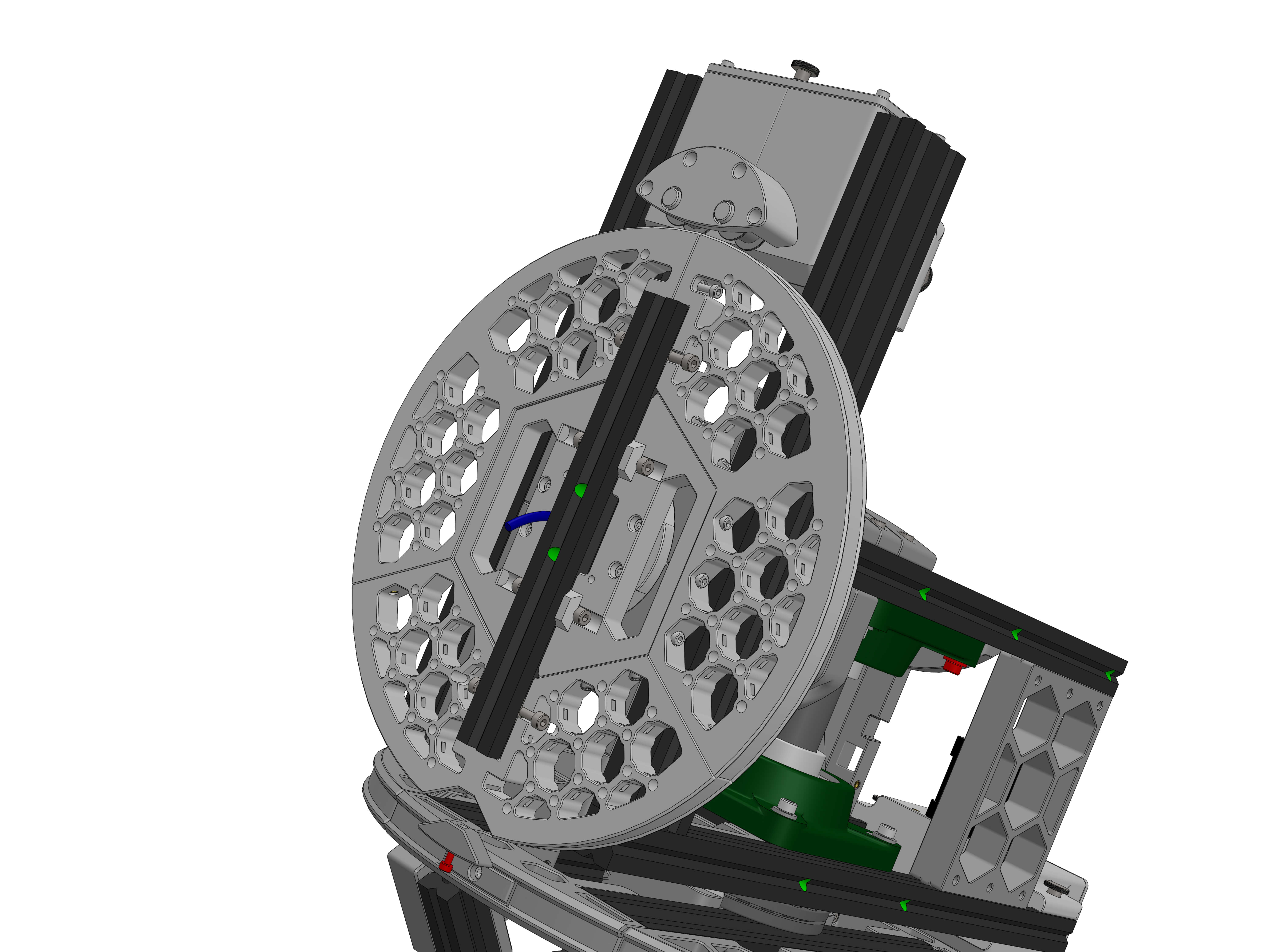
¶ Preparation
¶ Assembly
OAM Assembly Part 1: Base
OAM Assembly Part 2: ALTAZ base
OAM Assembly Part 3: Top Assembly
OAM Assembly Part 4: Gearboxes
OAM Assembly Part 5: Final Assembly
¶ OpenAstroMount Assembly Part 5: Final Assembly
¶ ALT Assembly
Parts:
- ALT_top
- ALT_top2 (2)
- brass threaded holder
Hardware:
- M3x10 screws (2)
- M5x12 screws (2)
- M4x12 screws (4)
- M4 T-nuts (4)
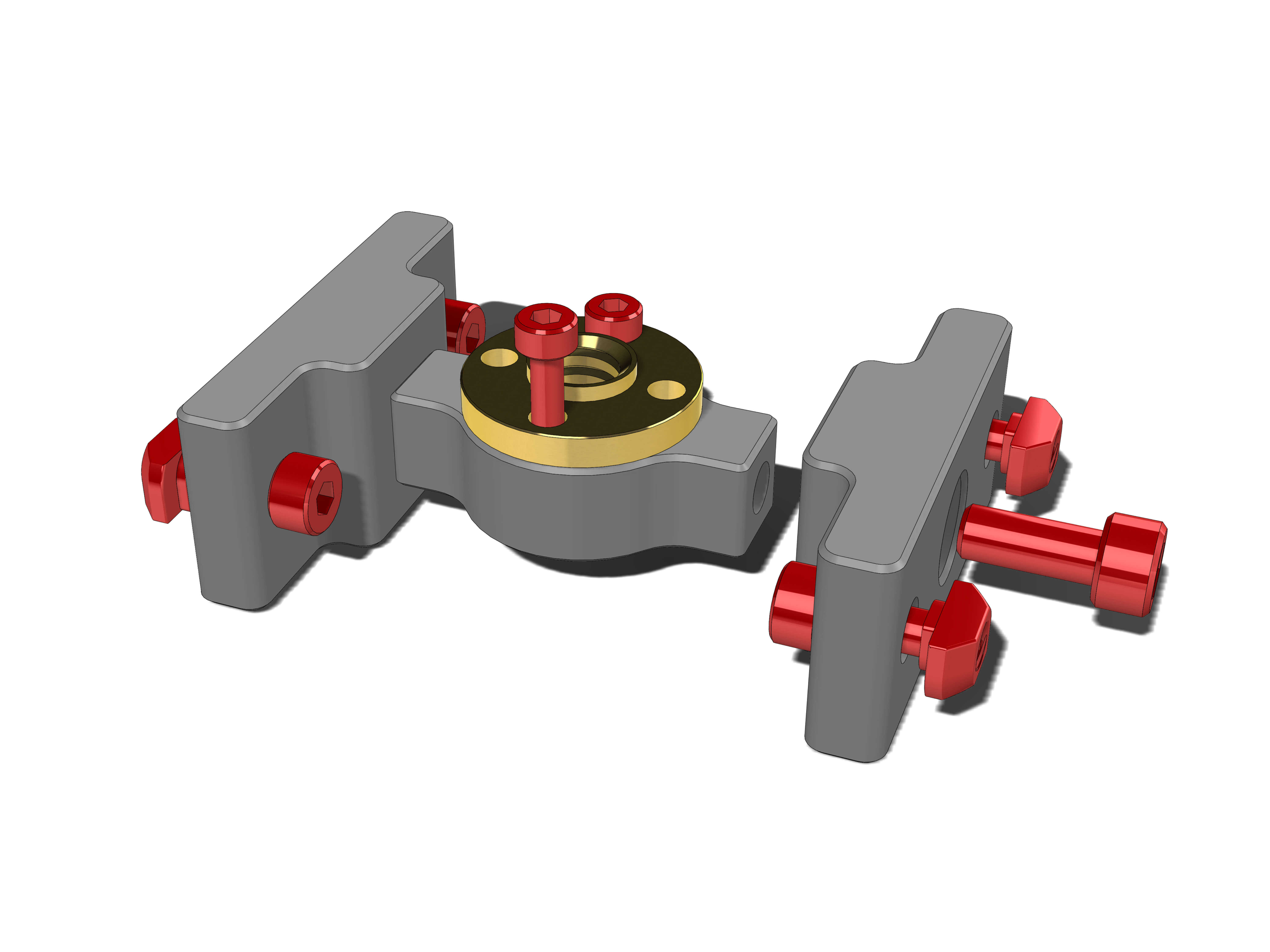
Assemble as shown. Use two M3x10 screws to secure the brass threaded holder to ALT_top2.
Insert two M4x12 screws and T-nuts in each ALT_top piece.
Use the M5x12 screws to attach the sides to the middle piece, being sure to not overtighten them, so that they can still pivot.
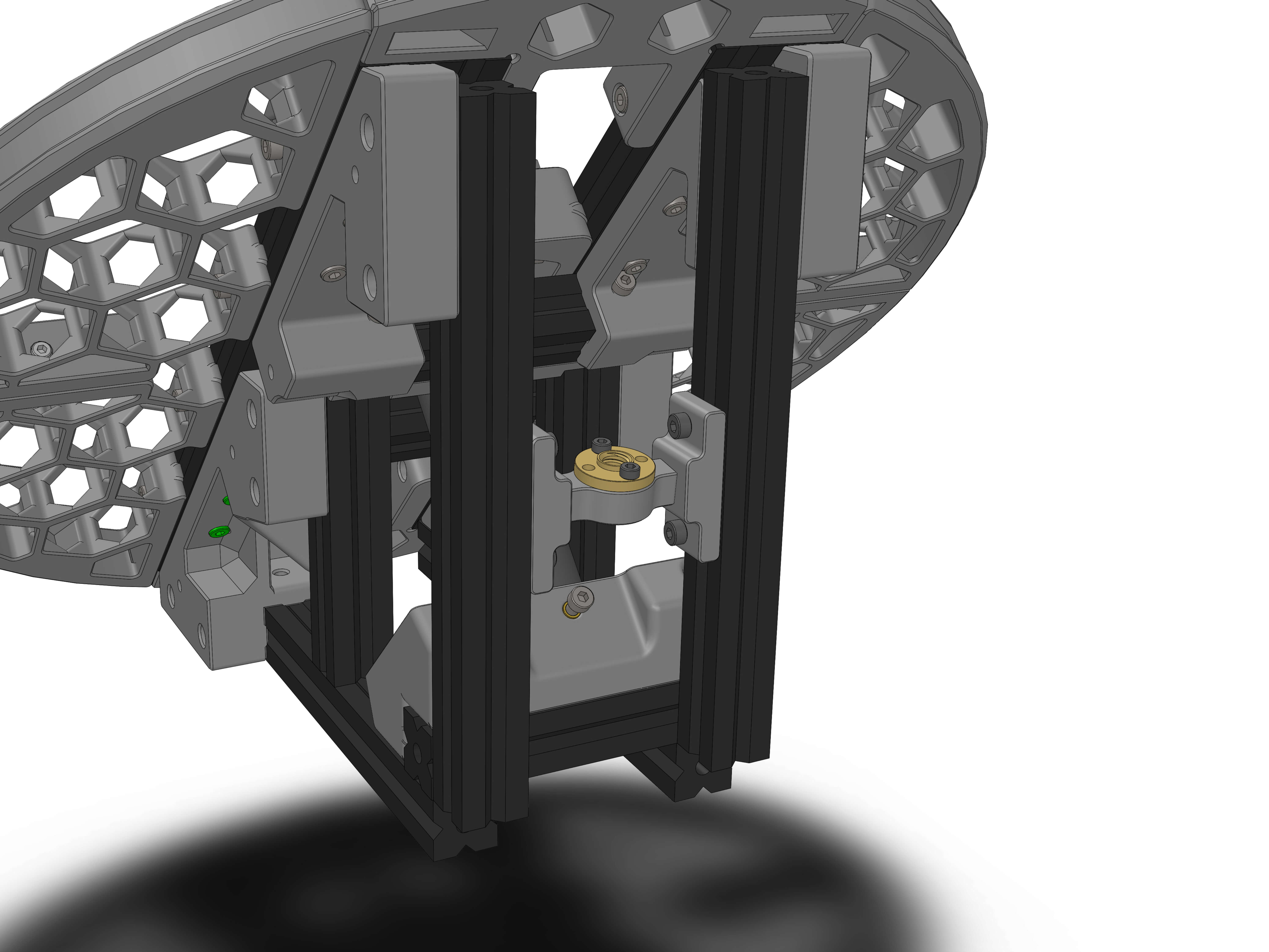
Then attach the assembled part in the top assembly on the rear profiles as shown (slide it in from the bottom) and secure it high enough that you can still get at the screw on the corner piece.
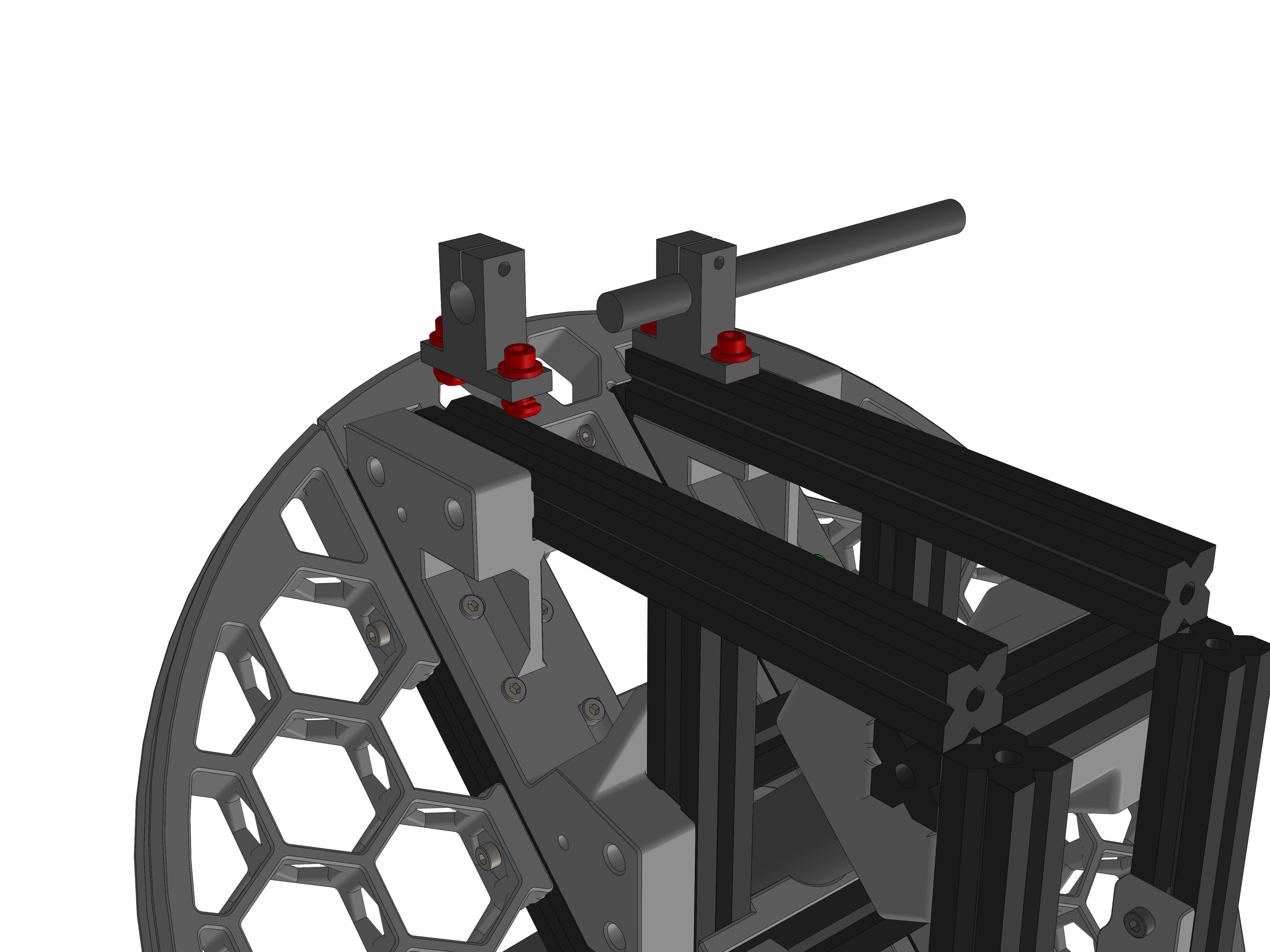
Hardware:
- 12mm x 150mm rod
- SK12 Rod Rail Shaft Support (2)
- M6 washers (4)
- M5x12 screws (4)
- M5 T-nuts (4)
Mount each of the supports on the bottom profiles as shown, don't tighten yet. Use the rod to line them up, but don't tighten the screws in the supports that grab the rod yet.
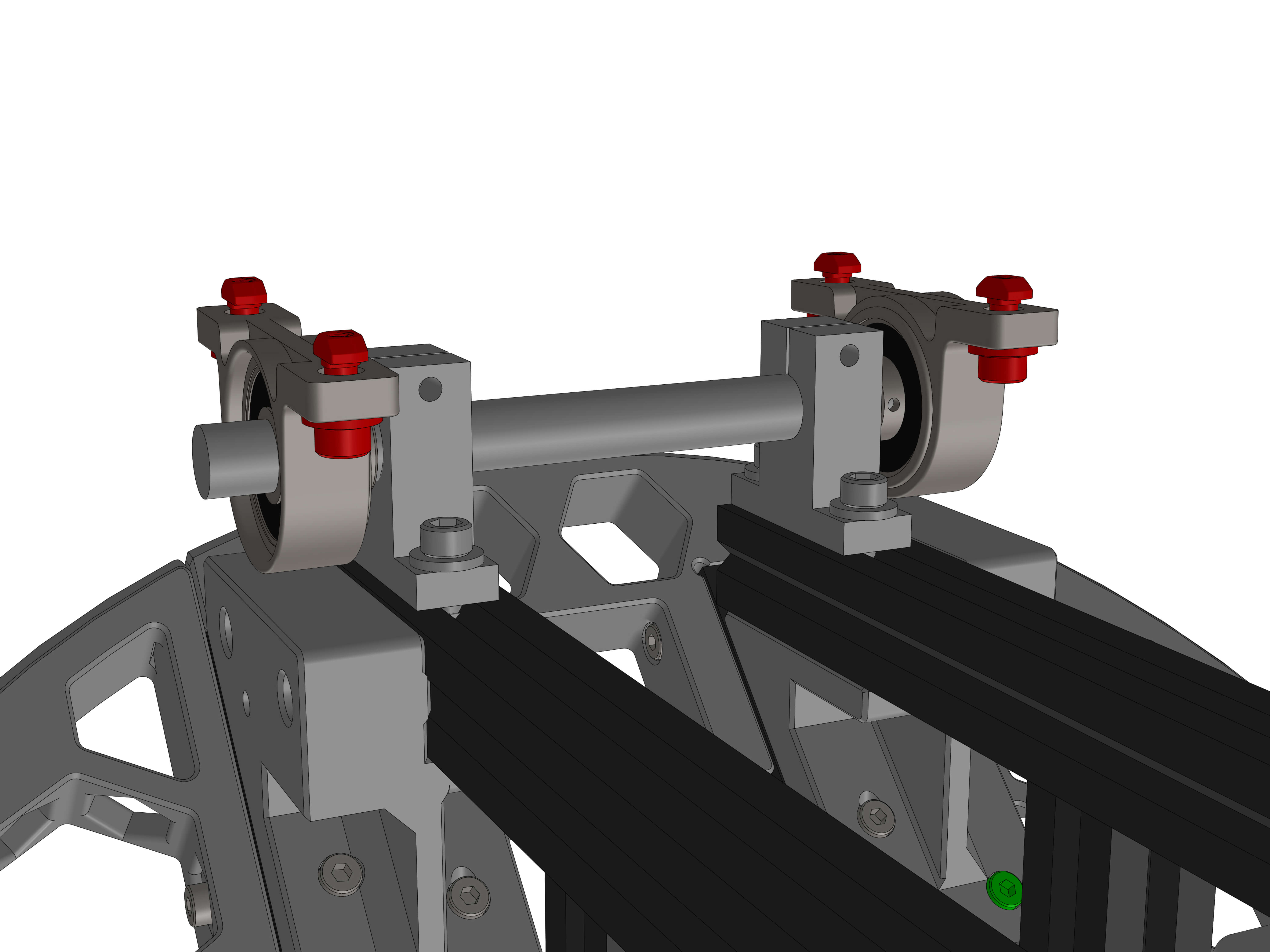
Hardware:
- KP001 12mm Block Inset Bearing (2)
- M5x12 screws (4)
- M6 washers (4)
- M5 T-nuts (4)
Loosen grub screws on block bearings and then slide one onto each side of the rod, grub screws on the inside. Center the rod and align the Shaft Supports with the end of the profiles and tighten the four M5 screws.
Insert the four M5x12 screws with M6 washers and the remaining four M5 T-nuts into the Block Bearings as shown.
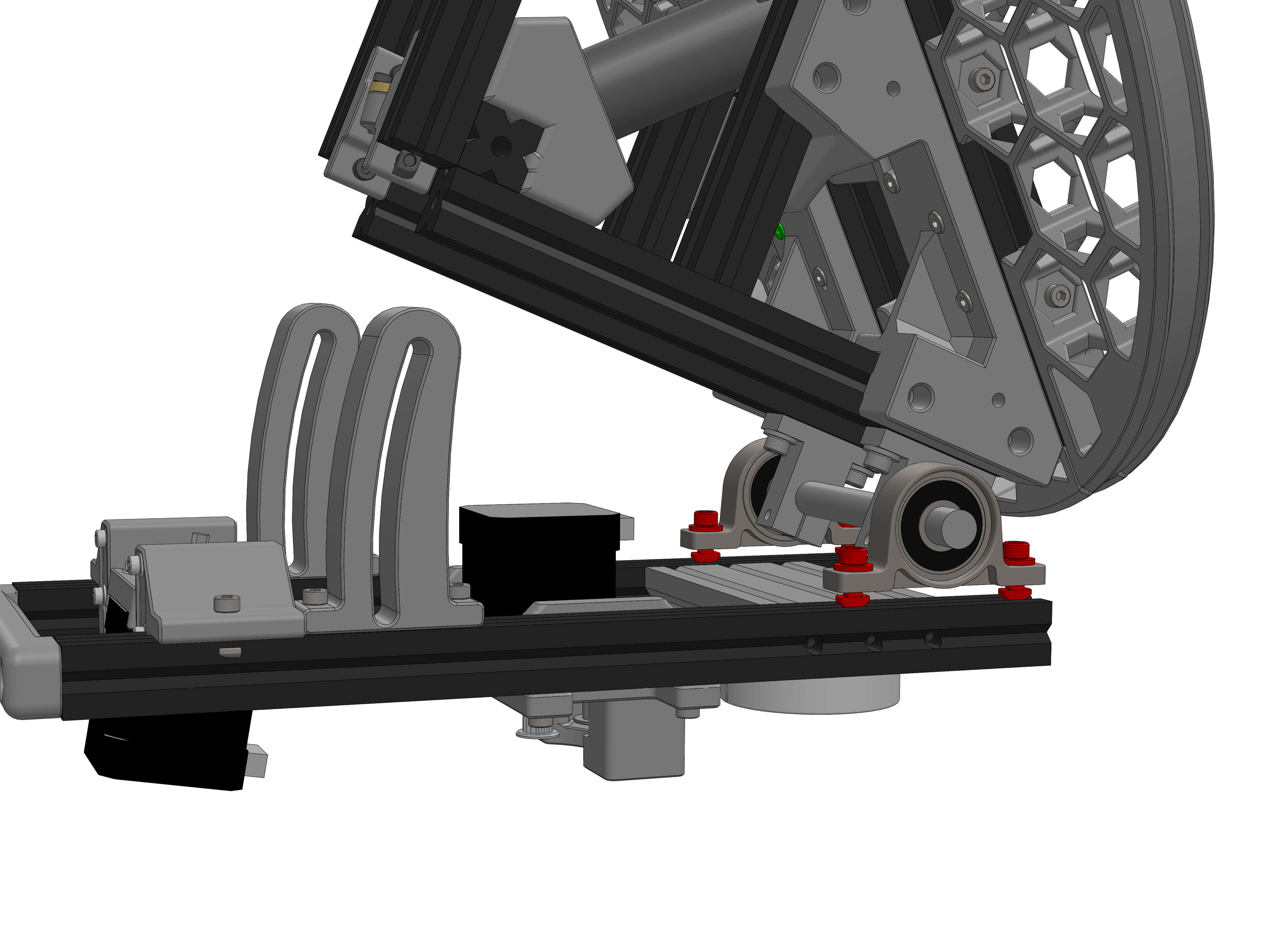
Place the top assembly onto the bottom assembly as shown. Place it such that the threaded holes in the aluminum profile of the top assembly can be seen centered through the slotted curved guide rails. Tighten the front two M5s (one on each side) and check that the assembly pivots easily with no rubbing or collisions anywhere.
Unfold the assemblies and tighten the back two screws of the Bearing Block as well. Ensure one last time that motion is free and that the top assembly does not touch the bottom assembly when rotate down.
Move the rod such that about 12mm stick out on the side facing the camera in the view below, measured from the edge of the aluminium extrusion.
Tighten the grub screws on the bearings and the screws on the SK12 Shaft Supports. You may need to rotate the bearing sleeves with the grub screws such that one can be tightened when the assembly is open and one when closed.
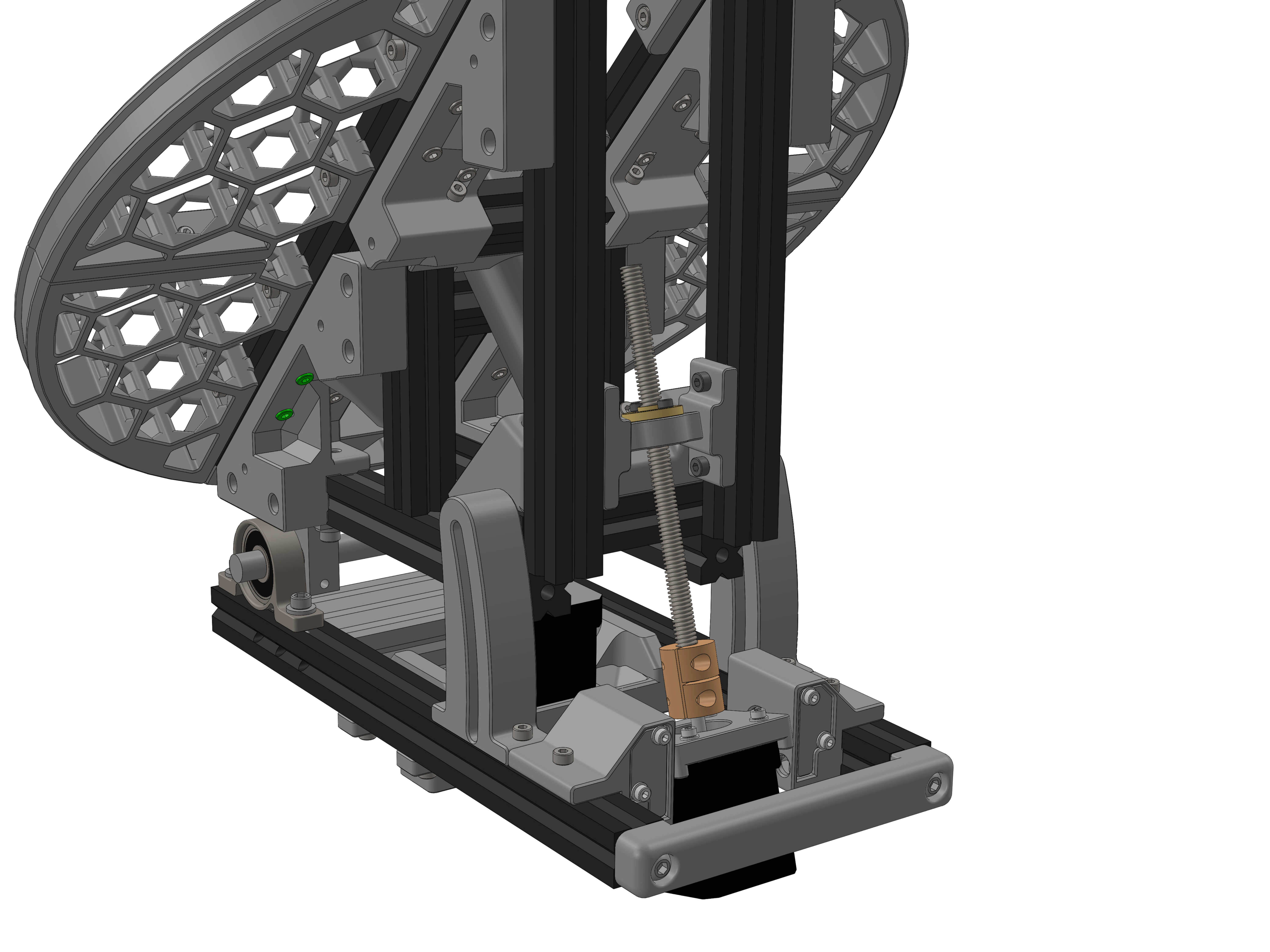
Hardware:
- 3mm-5mm Shaft coupling
- Threaded pushrod
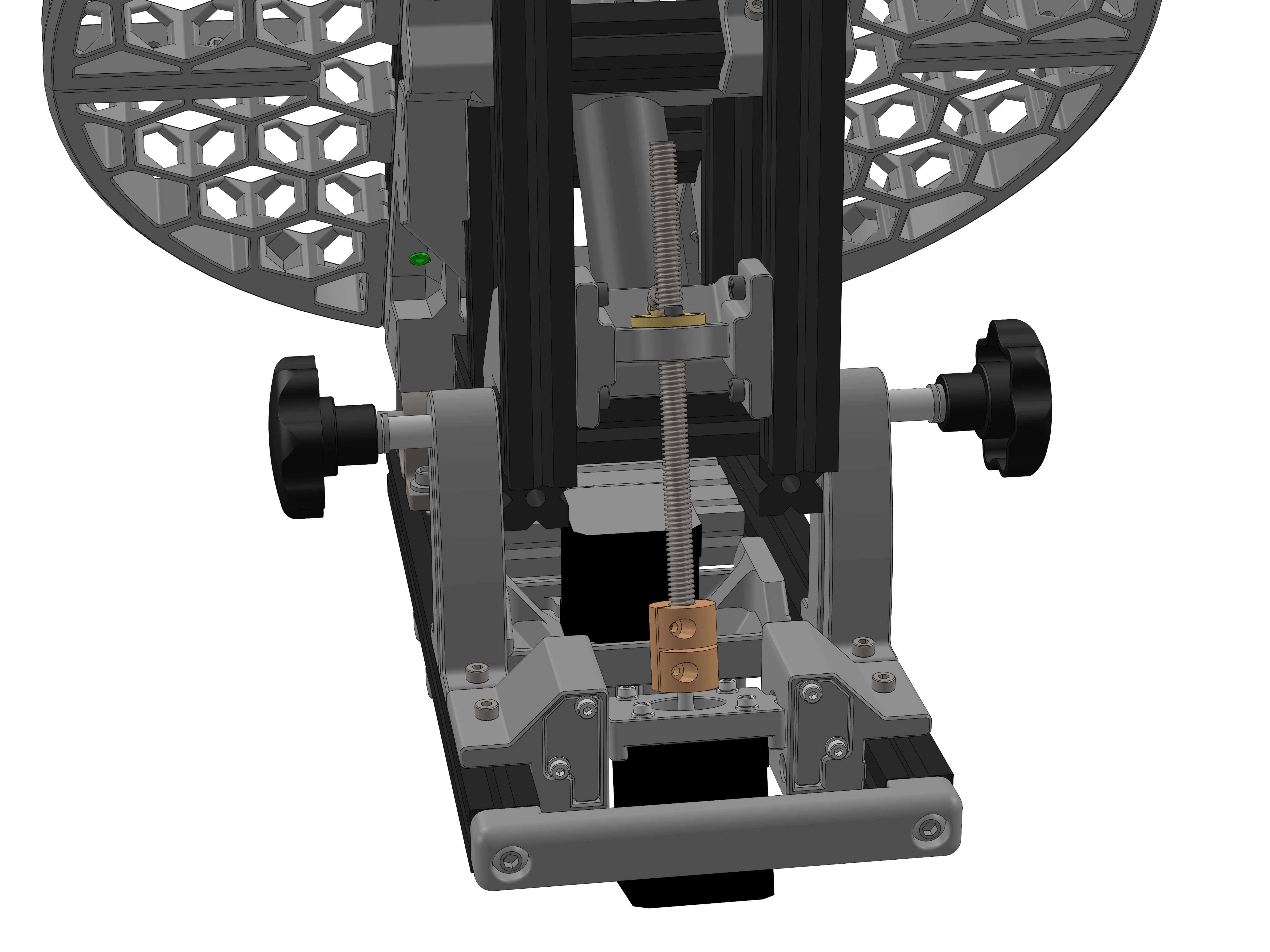
Screw pushrod into the brass ring attached to top assembly. Place coupling over stepper motor shaft, looking in the top to make sure the stepper shaft does not protrude out of the 3mm hole in the 5mm space. Tighten coupling screw on 3mm side. Thread the rod as far as needed so that the top assembly does not rest on the bottom assembly when the push rod is inserted in to the coupling and insert it into the 5mm side of the coupling. Tighten the 5mm coupling side holding the push rod.
Hardware:
- Thumbscrews (2)
Insert the two thumbscrews into the 100mm extrusion ends from either side through the guide rails.
Parts:
- ALT_indicator
- ALT_clock
Hardware:
- M4x10 screw
- M4 T-nut
- M3x12 screw
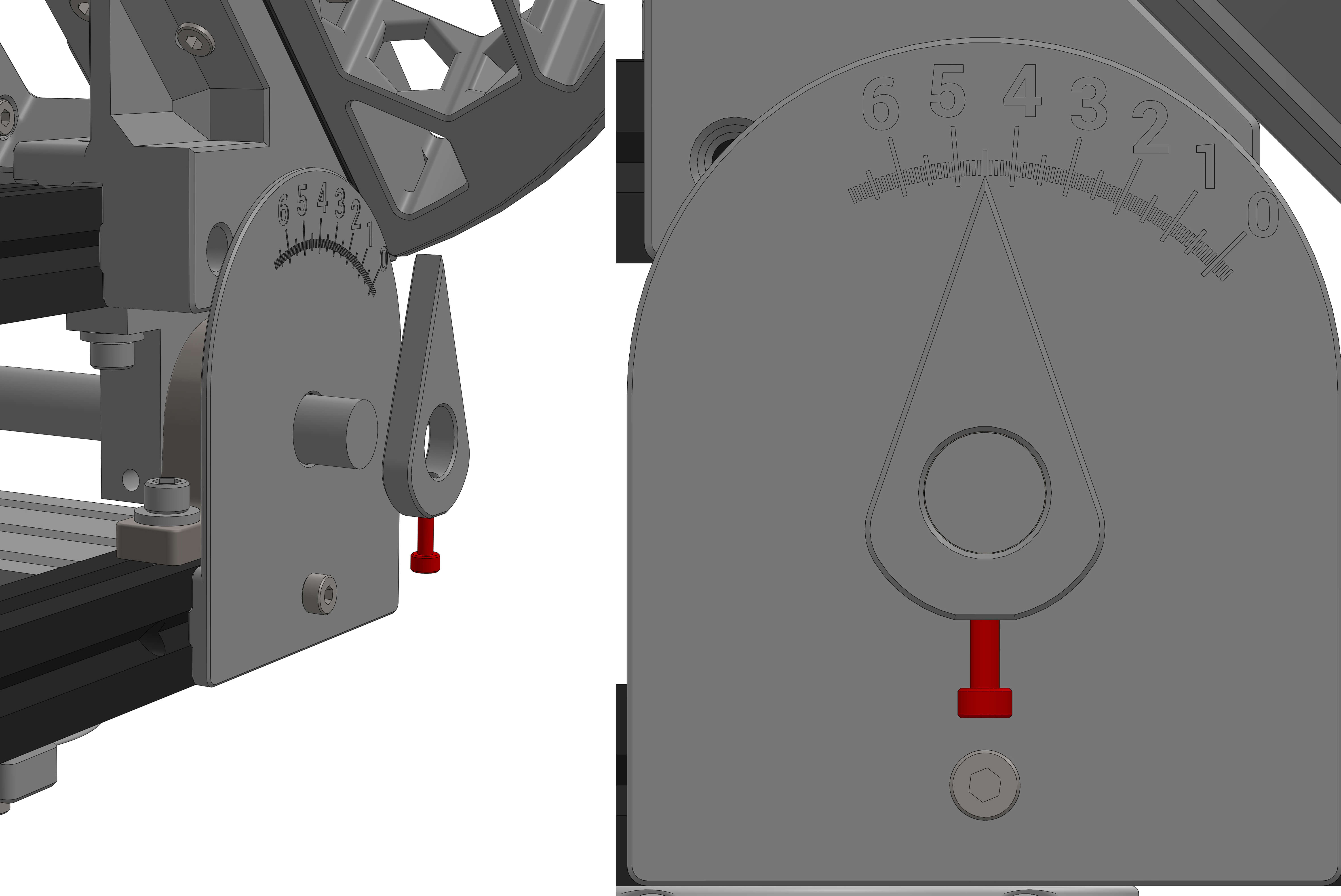
Insert M4 screw through front of clock and attach M4 T-nut. Insert into Profile and tighten in place, letting the rod show through.
Make sure that the profiles of the top and bottom assembly are parallel and then insert M3 screw into indicator, attach to rod, and tighten such that it is indicating 45 degrees.
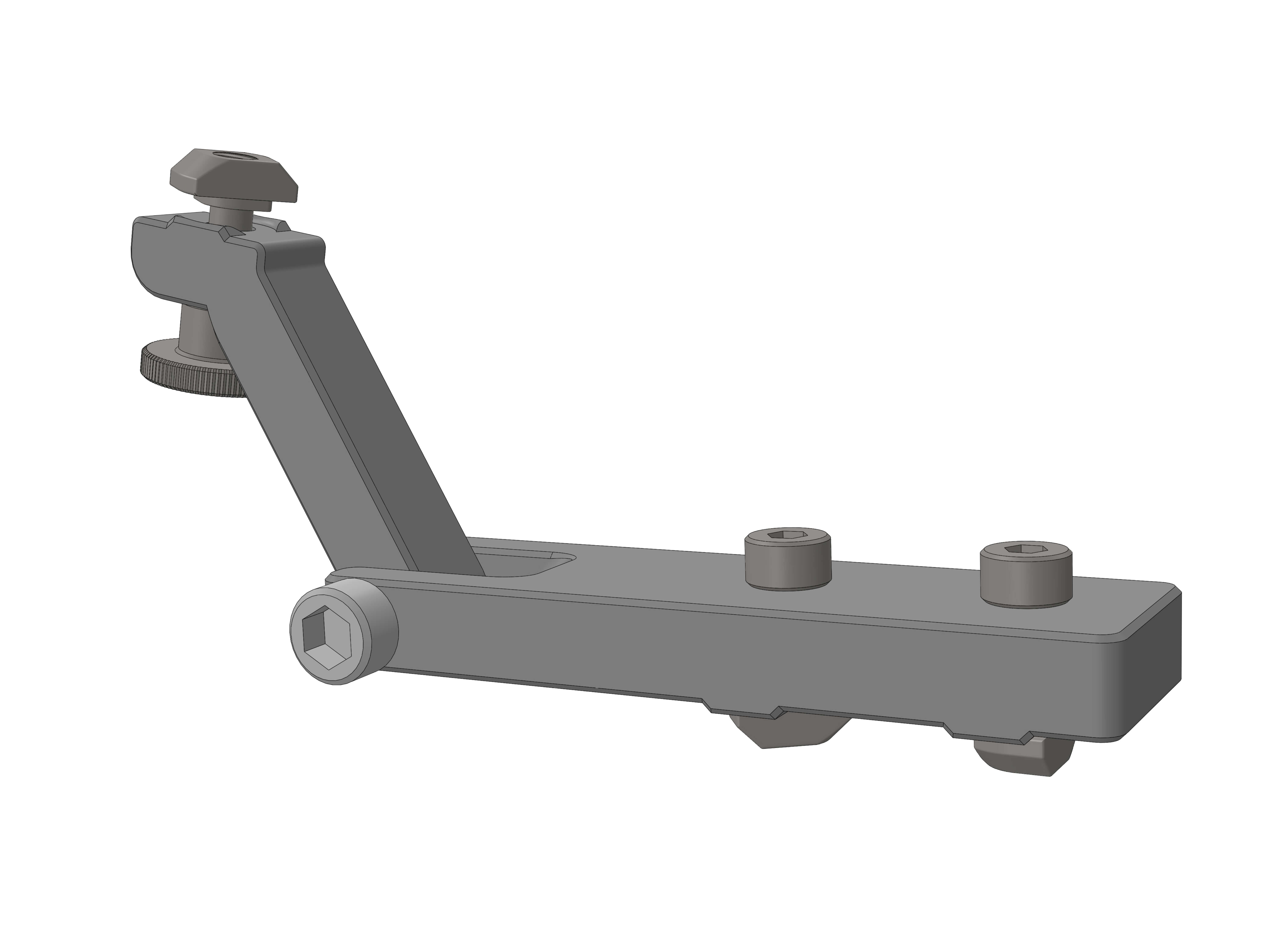
Parts:
- Parkingbreak_1
- Parkingbreak_2
Hardware:
- ? M4x12 screws (2)
- ? M4x20 screw
- ? M4 thumbscrew
- ? M4 T-nuts (3)
Assemble as shown.
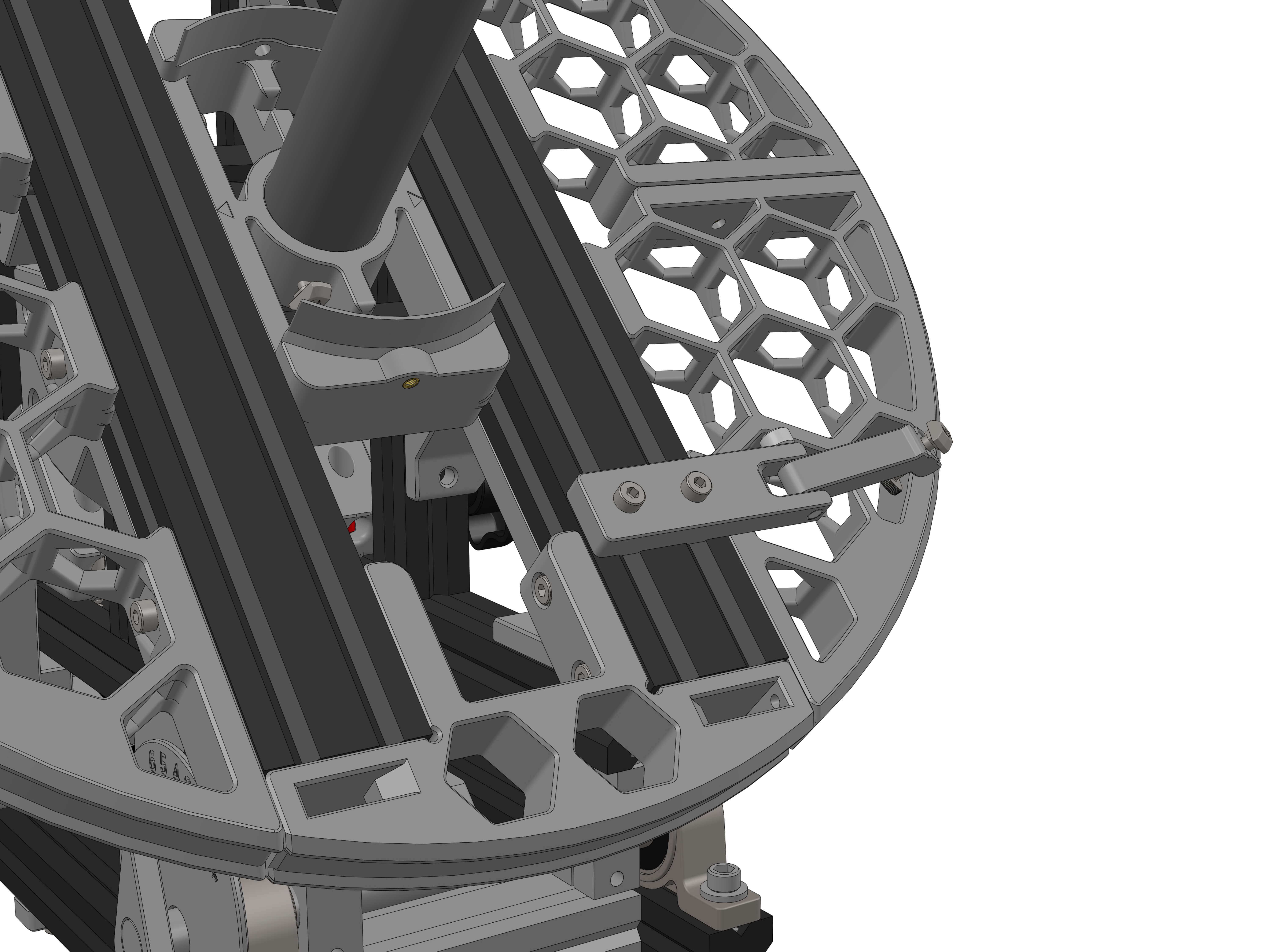
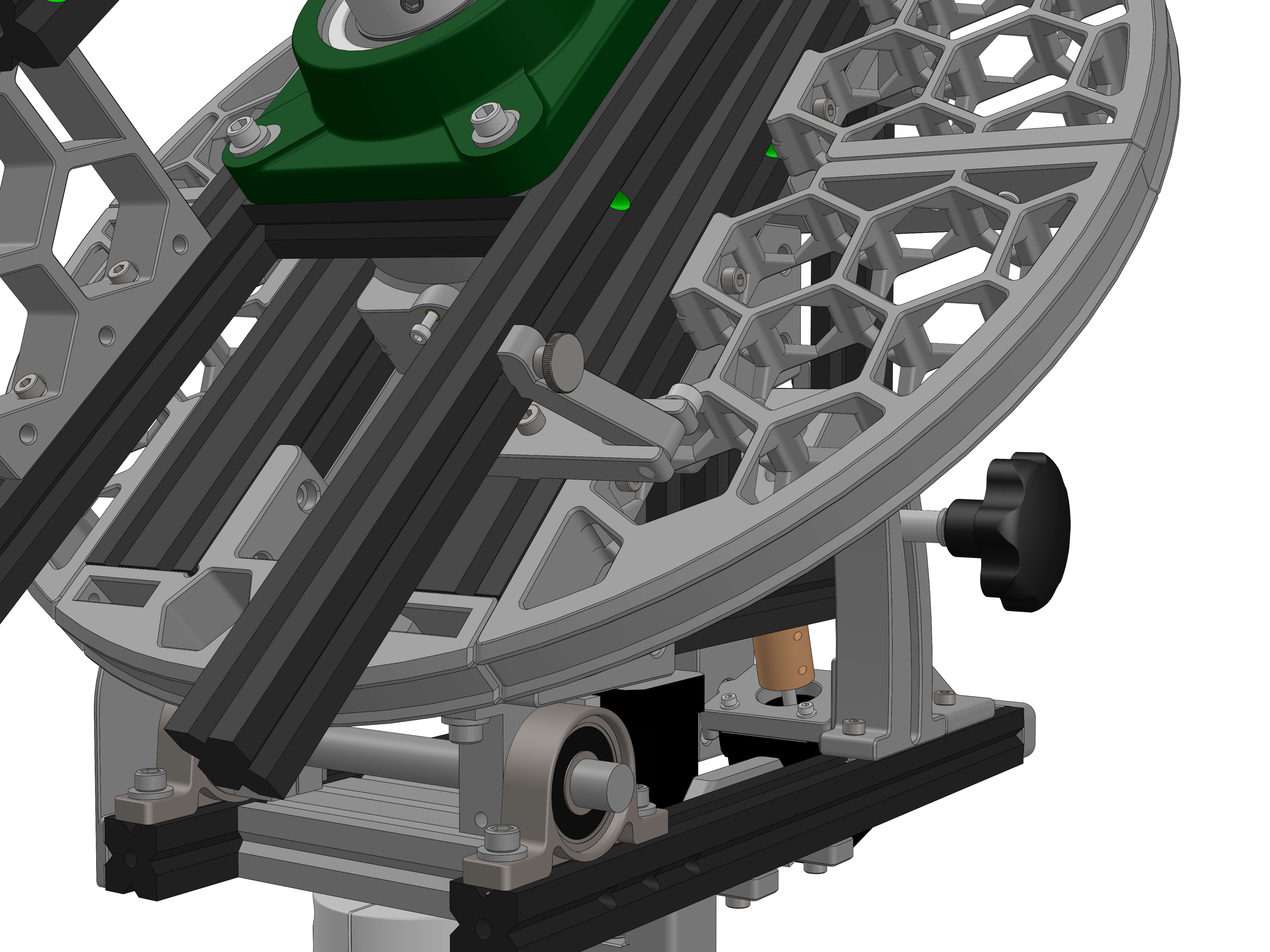
Mount the parking brake assembly on the 2040 extrusion of the RA ring as shown.
Hardware:
- 51115 Bearing
- M3x12 screws (2)
Place the bearing on the RA ring as shown and secure in place with the screws.
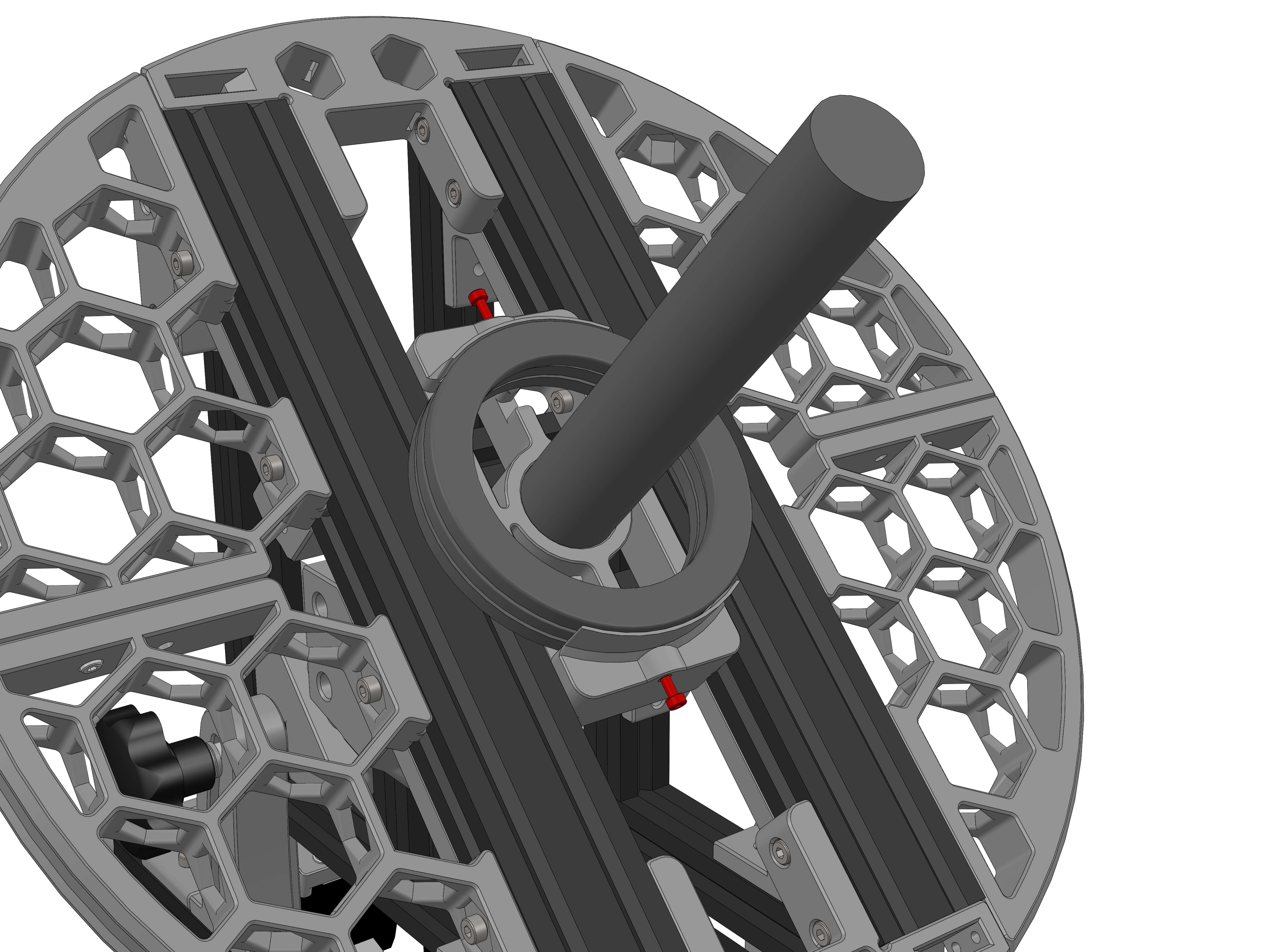
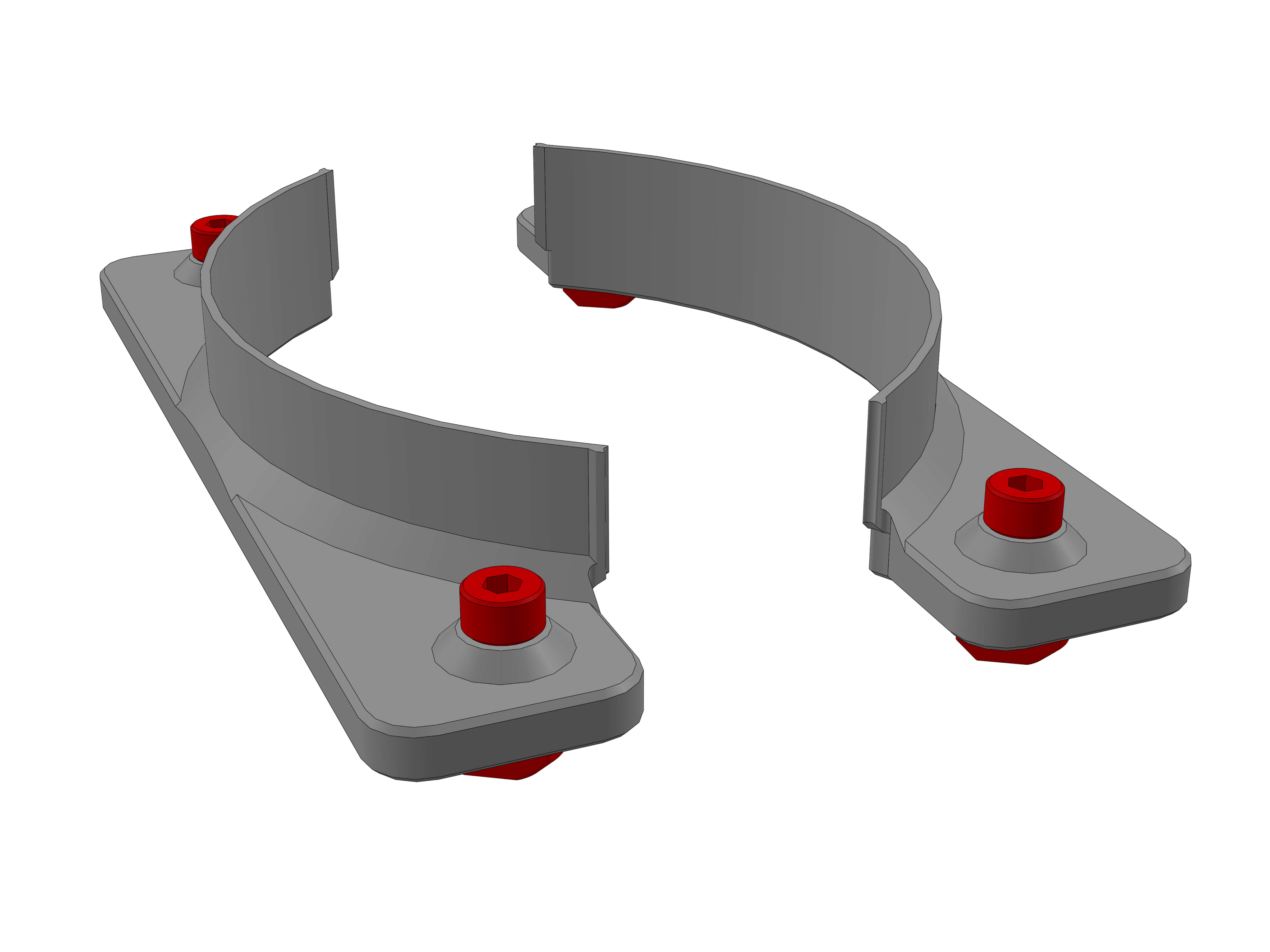
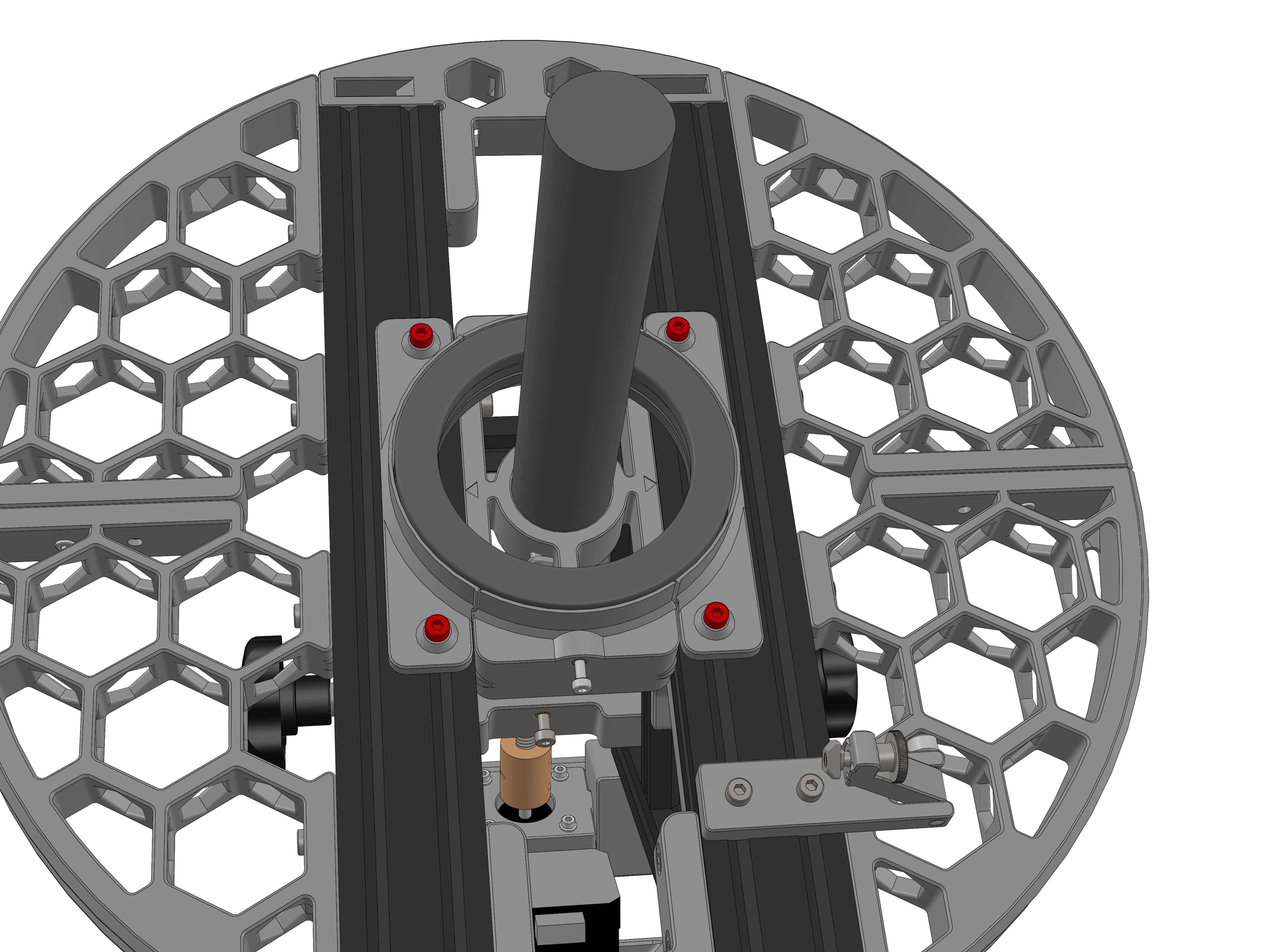
Now push the DEC assembly onto the 30mm shaft of the bottom assembly. Make sure any grub screws are loose enough to not obstruct the insertion. Since the fit is going ot be pretty tight, take your time and wiggle, hammer and coerce it onto the shaft.
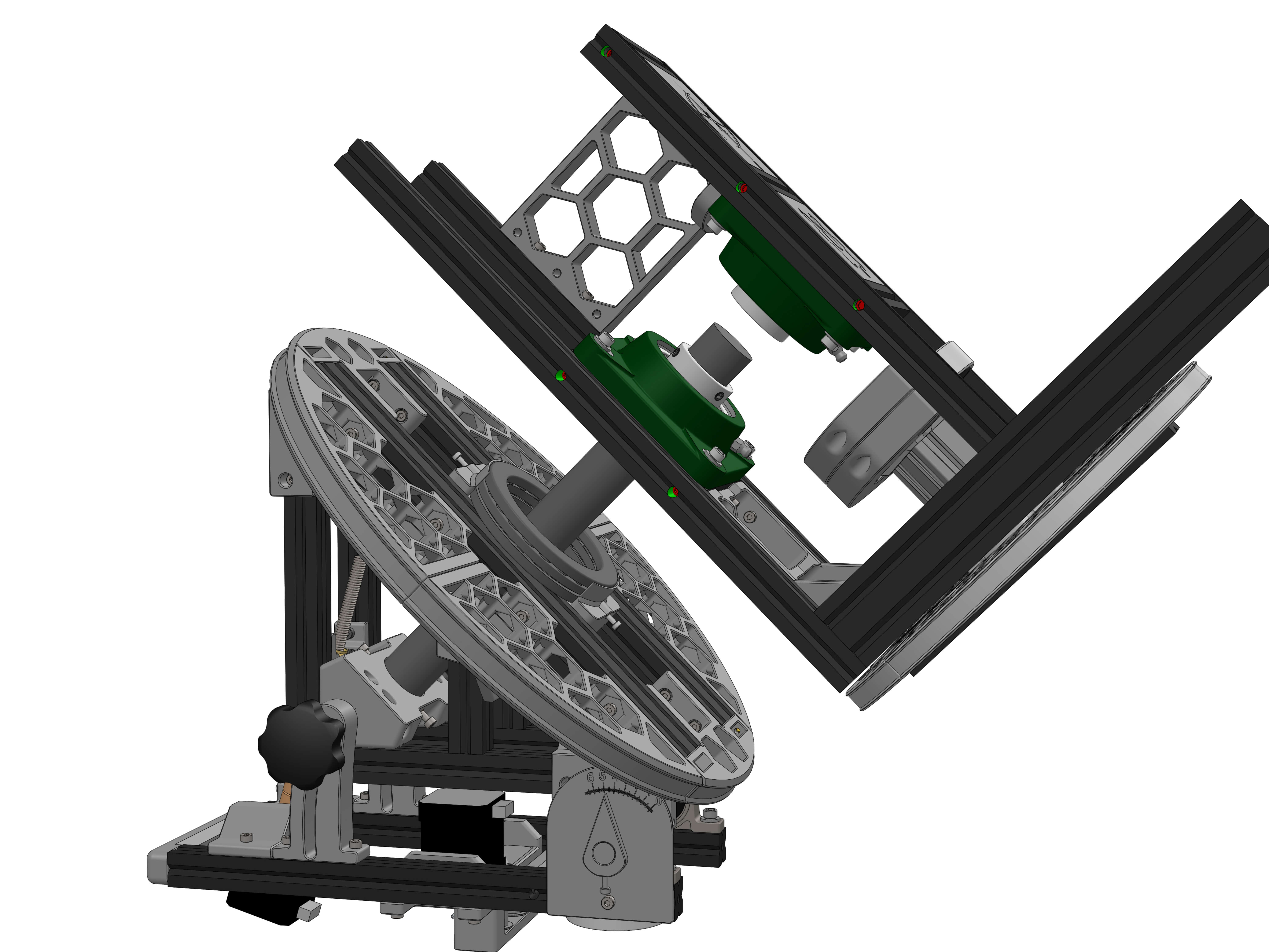
Use the parking brake as shown to stop the DEC ring from rotating.
¶ Electronics
Parts:
- MKS_enclosure
Hardware:
- MKS Board
- ? M3x6 screws (4)
- ? M4x12 screws (4)
- ? M4 T-nuts (4)
- M3 Threaded inserts (4)
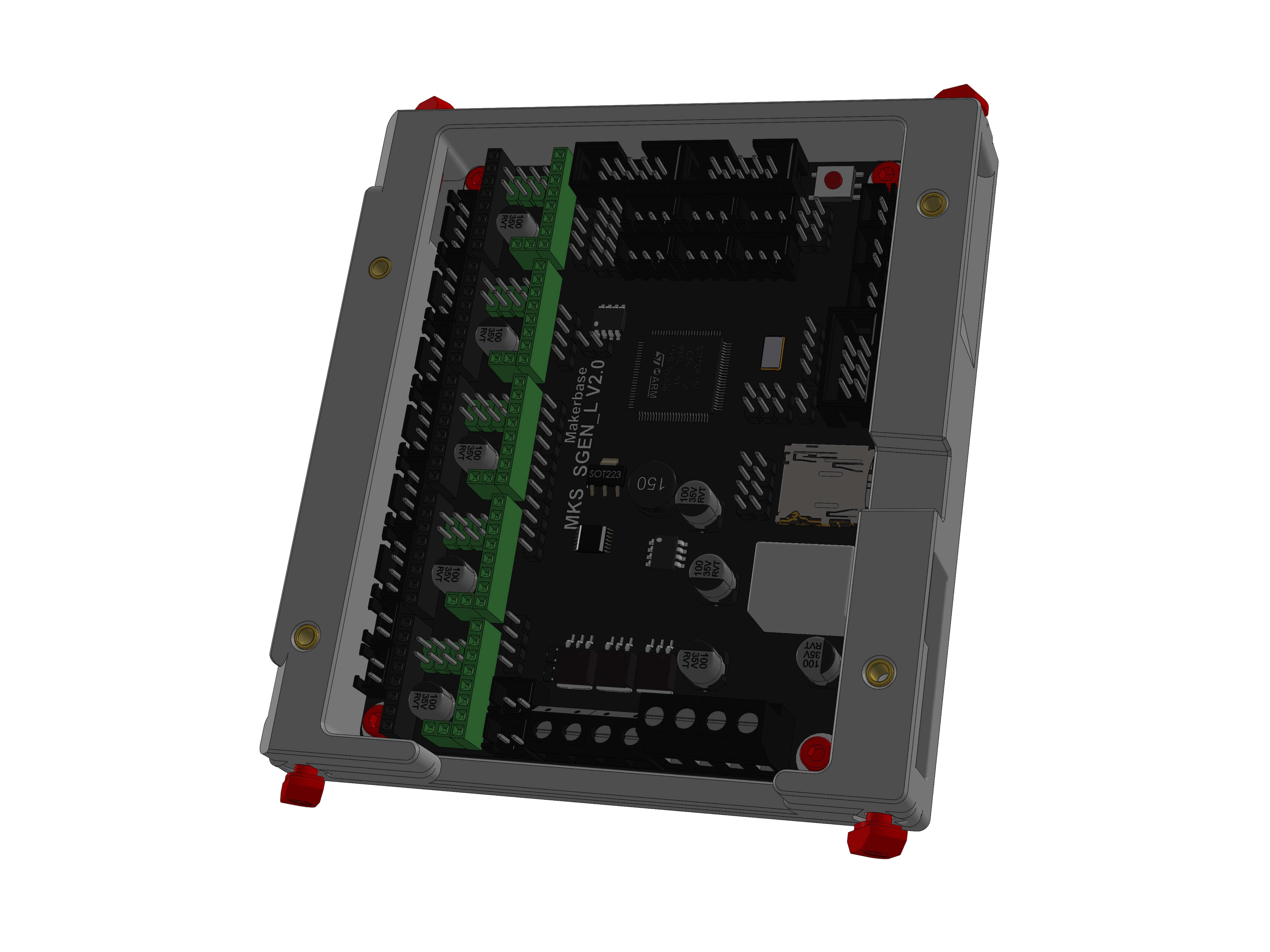
Insert the threaded inserts as show on the enclosure top face.
Mount the board with the 4 screws into the enclosure.
Insert the four M4x12 screws and T-nuts.
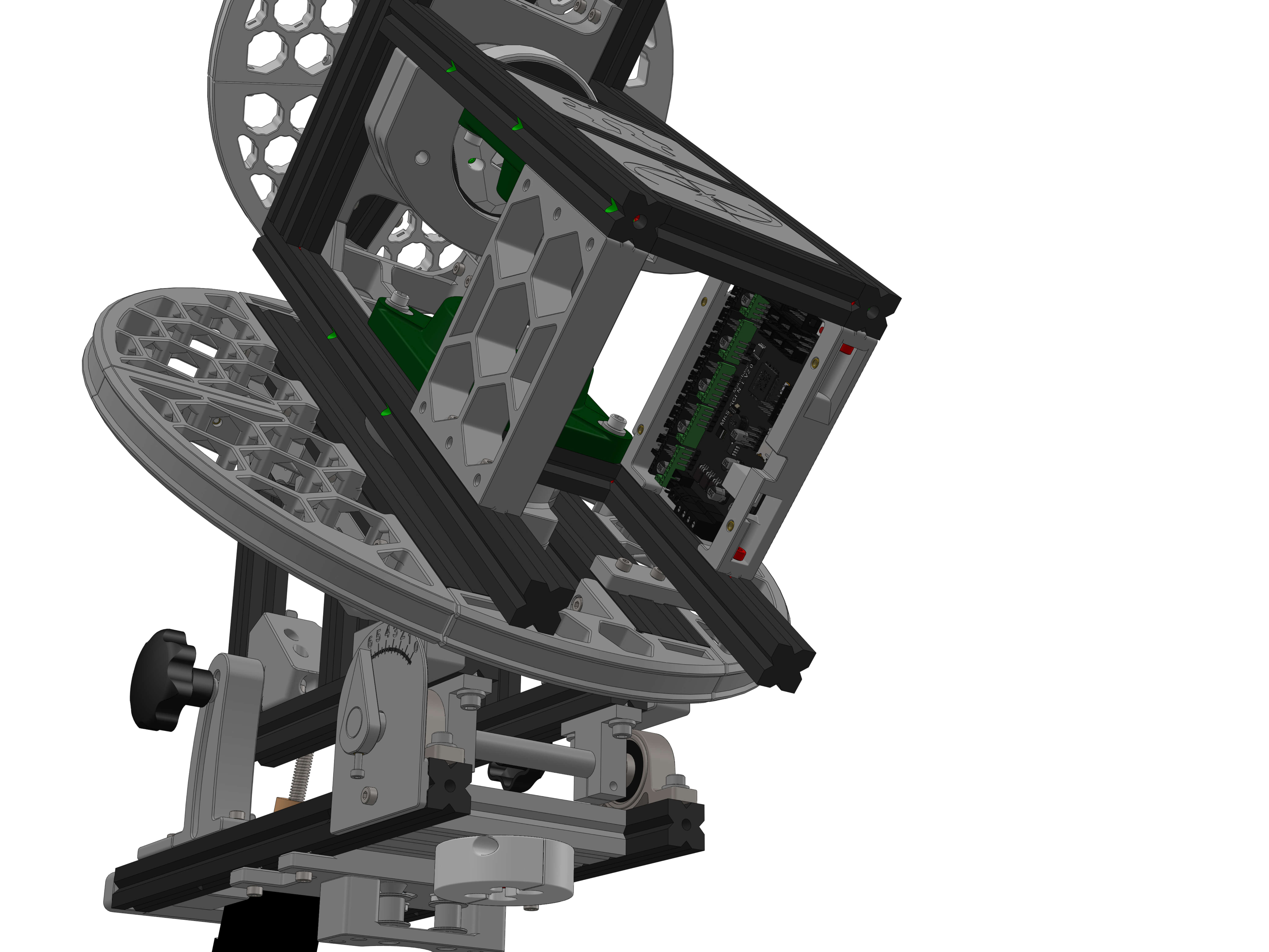
Mount the board between the aluminium profiles of the top assembly as shown.
Parts:
- Belt_retainer
Hardware:
- ? M3x12 screw
- M3 Threaded insert (2)
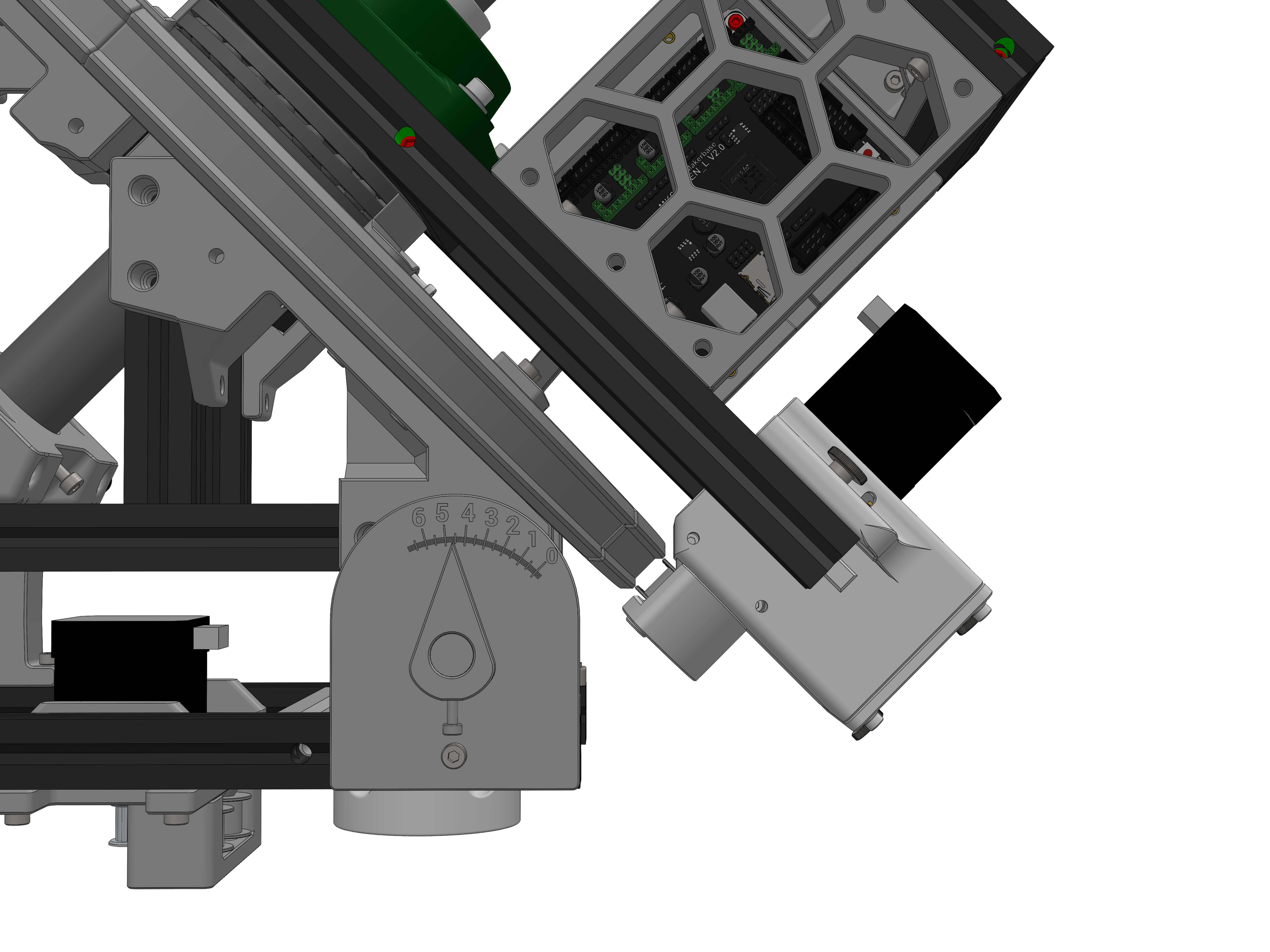
Insert the threaded inserts into the DEC and RA rings as shown.
