¶ Preparation
¶ Assembly
OAM Assembly Part 1: Base
OAM Assembly Part 2: ALTAZ base
OAM Assembly Part 3: Top Assembly
OAM Assembly Part 4: Gearboxes
OAM Assembly Part 5: Final Assembly
¶ OpenAstroMount Assembly Part 3: Top Assembly
In this step:
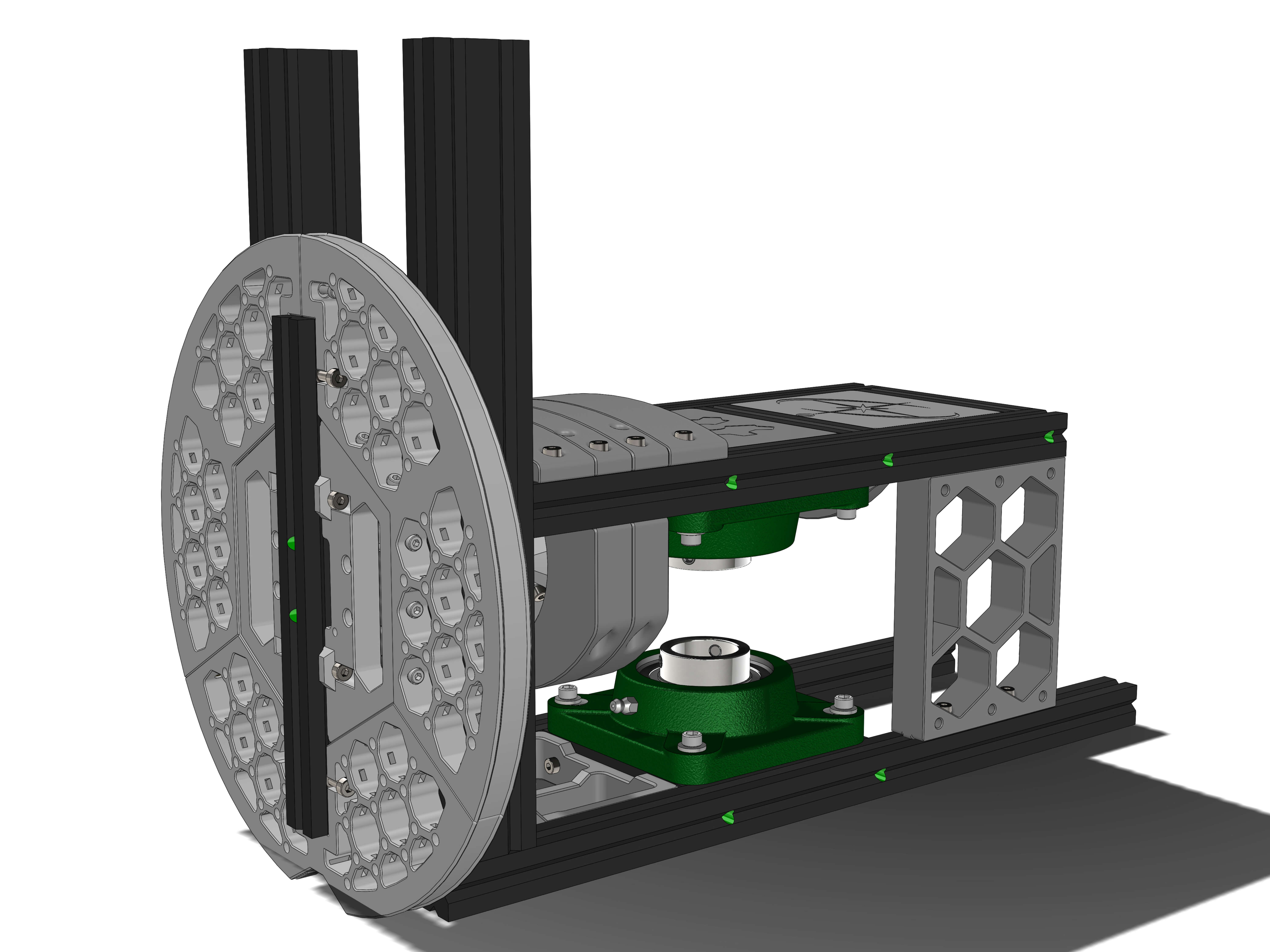
Parts:
- Baseplate_1
Hardware:
- 2020: 400mm (EX-D)
- M4x12 screws(10)
- M4 T-nuts (10)
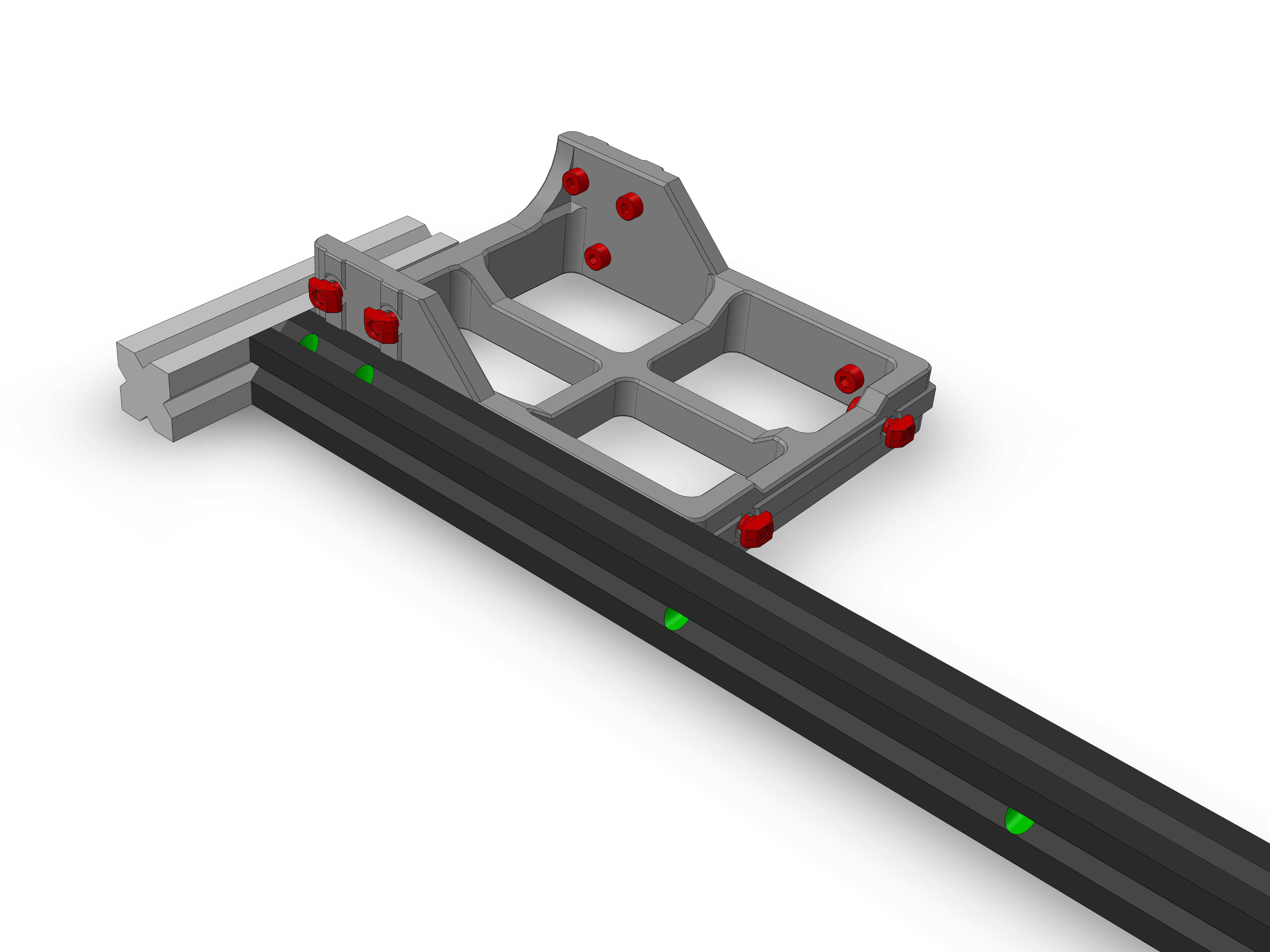
Insert all 10 M4x12 screws and T-nuts into the holes on the Baseplate part. Attach the Baseplate to the 400mm extrusion as shown. Use an extra extrusion for alignment. Note the orientation of the drill holes (green).
Hardware:
- 2020: 100mm (EX-G)
- M5/6x20 screws (2)
(If using blindjoints) Attach M5/M6 bolts on both sides of the 100mm extrusion. Slide it into position, lightly tighten the M5/M6 bolt, then tighten the two M4 screws on the Baseplate to torque 4. Then tighten the M5/M6 bolt to torque 5.
Parts:
- Baseplate_2
Hardware:
- M4x12 screws (4)
- M4 T-nuts (4)
Attach the M4x12 screws and T-nuts to each side of the Baseplate_2. Attach it as shown and tighten the screws to torque 4.
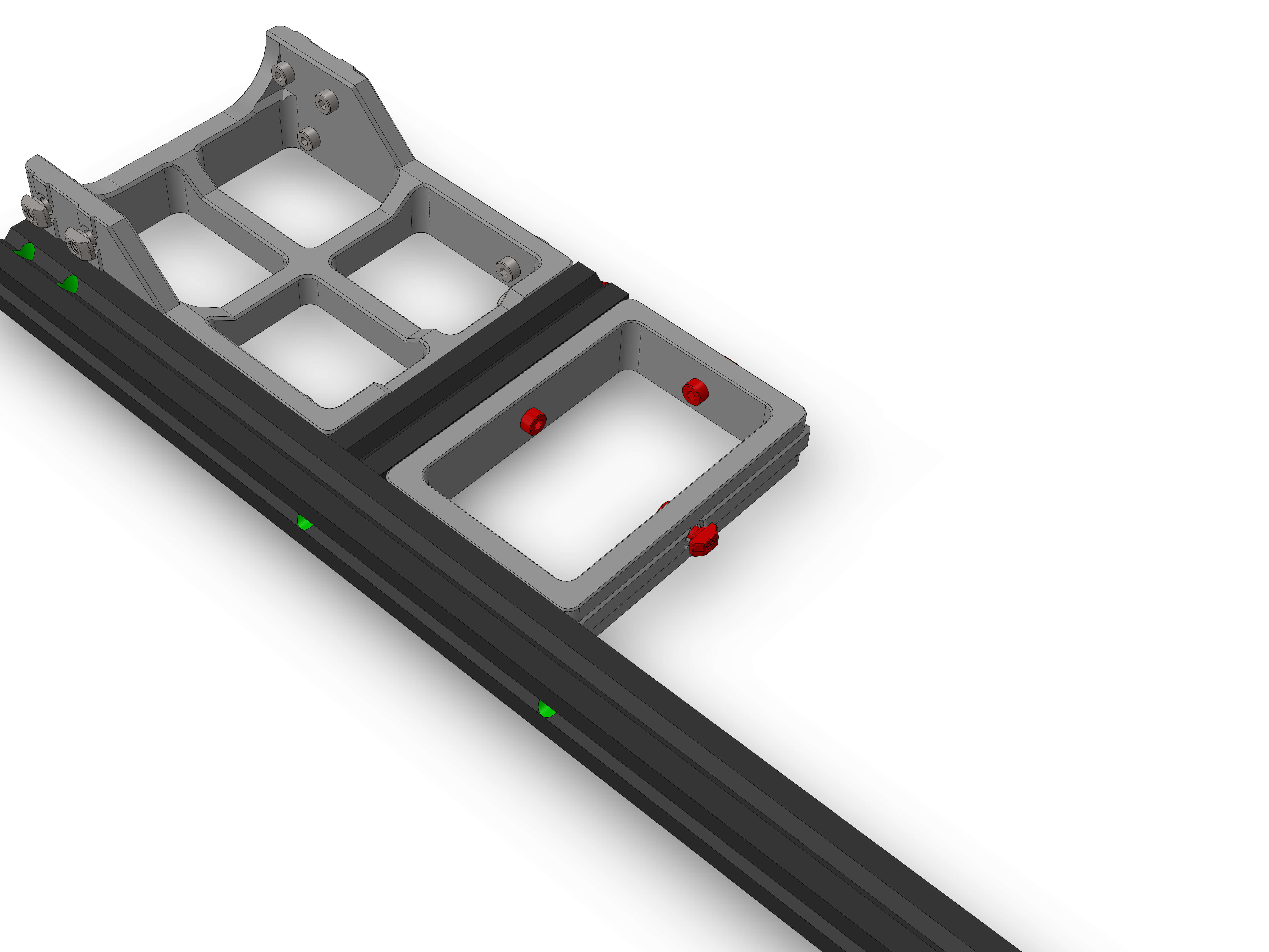
Hardware:
- 2020: 100mm (EX-G)
- M5/6x20 flathead screws (2)
(If using blindjoints) Attach M5/M6 bolts on both sides of the 100mm extrusion. Slide it into position, lightly tighten the M5/M6 bolt, then tighten the M4 screw on the Baseplate to torque 4. Then tighten the M5/M6 bolt to torque 5.
Hardware:
- 2020: 400mm (EX-D)
Slide the 400mm extrusion on as shown. Note the orientation of the drill holes (green). Use a extrusion for alignment to the baseplate.
First lightly tighten the M5/M6 bolts, then tighten all M4 screws to torque 4. Then tighten the two M5/M6 bolts to torque 5.
Parts:
- UCF206_M5_adapter (4)
Hardware:
- UCF206 bearing
- M5x20mm screws (4, not flatheads)
- M6 washers (4)
- M5 T-nuts (4)
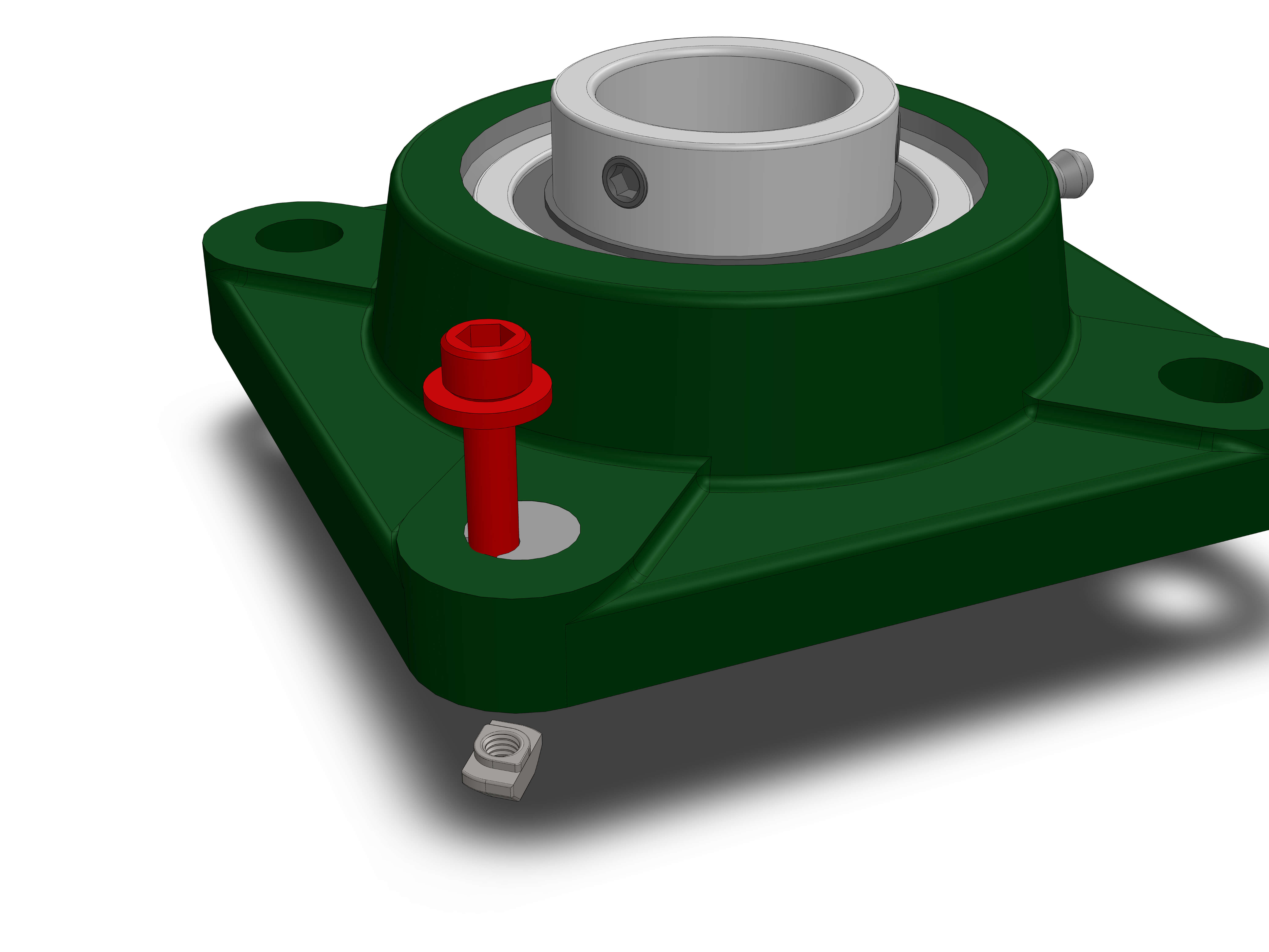
Insert the UCF_adapter, M5 screw and M6 washer as shown. The UCF_adapter should be able to move slightly. Then attach a M5 T-nut at the bottom.
Repeat this for all 4 holes of the UCF206.
If the bearing did not come straight in its block, you have to align it yourself. this is pretty easy, watch this vide for more information https://youtu.be/ymFkxmZDLB4
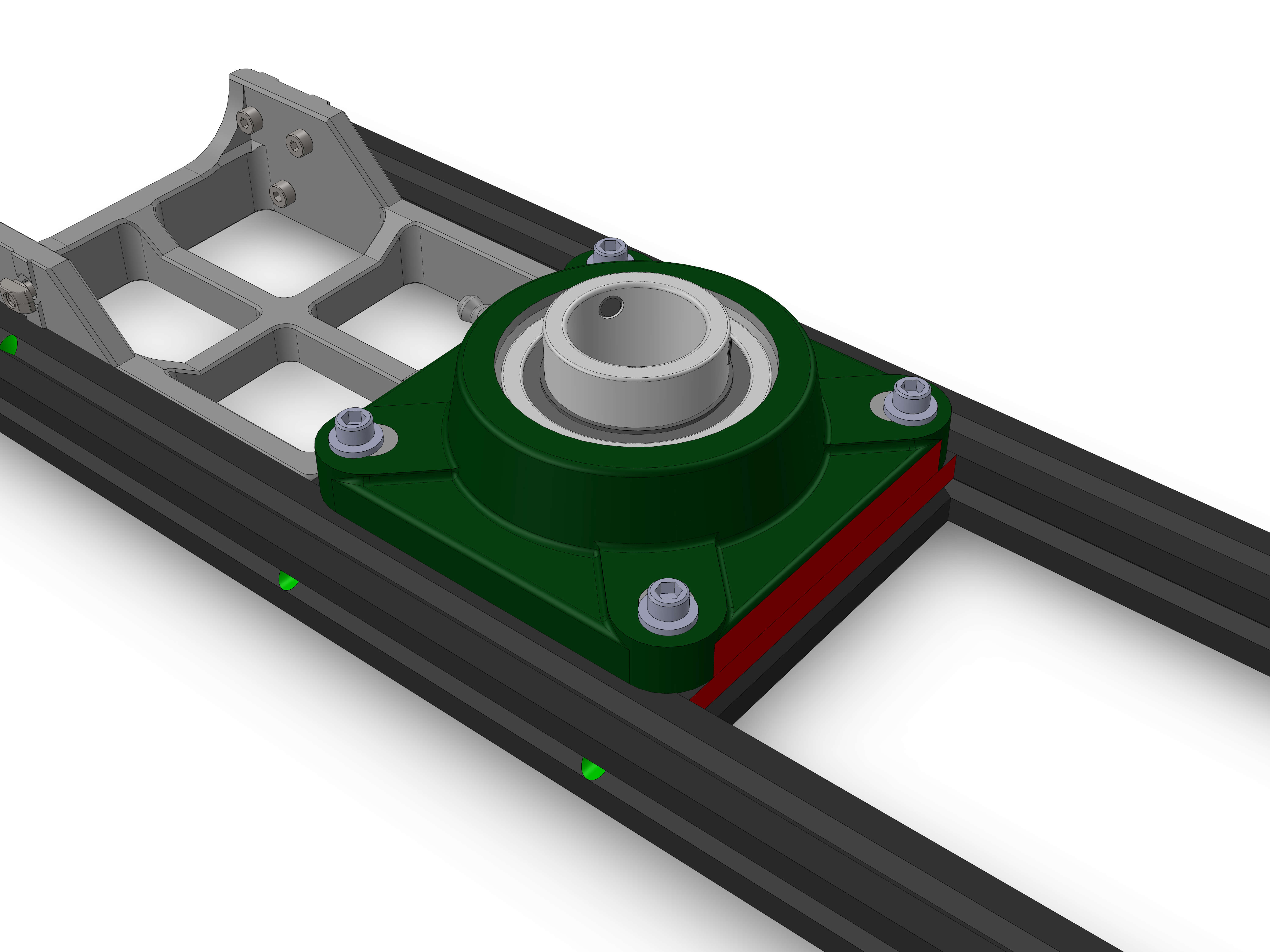
Place the UCF206 with the screws and T-nuts attached as shown. The greasing input (the little protrusion) should face the front Baseplate.
You can move the UCF_adapter parts to adjust the position of the screws so they match the extrusion slots.
The two red highlighted surfaces should align.
Make sure the bearing is centered, then tighten the M5 screws carefully. Make sure the bearing does't move while tightening.
Hardware:
- 2040: 300mm (EX-E)
- M5/6x20 flathead screws
Take one of the 2040 extrusion and if using blindjoints attach two M5/M6 bolts at the bottom. You need to let them stick out a good bit.
Note position of the 3rd drill hole (green), it is on the shorter side.
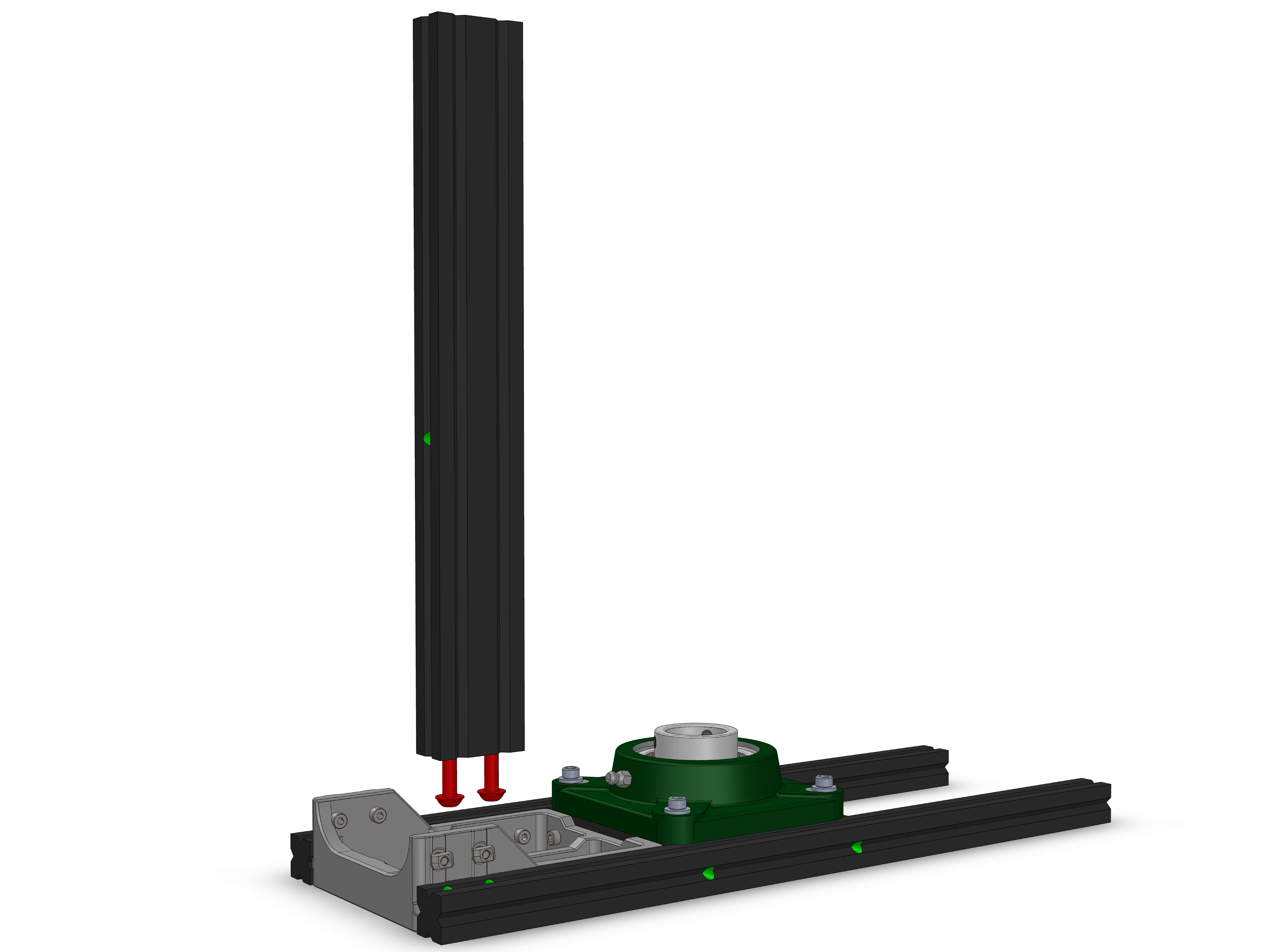
Slide the extrusion is as shown below
(If using blindjoints) To tighten the bolts, you need to tighten them in an alternating fashion, to prevent them from binding. Check that the M4 T-nuts on the baseplate line up with the extrusion slots as the 2040 extrusion slides into place.
Lightly tighten the bolts, then tighten the two M4 screws on the baseplate to torque 4. Then fully tighten the bolts to torque 5.
Do this again with a second 2040 extrusion on the opposite side (TODO add image?).
Hardware:
- 2020: 300mm (2) (EX-C)
- 2020: 100mm (EX-G)
- M5/6x20 buttonhead screws (2)
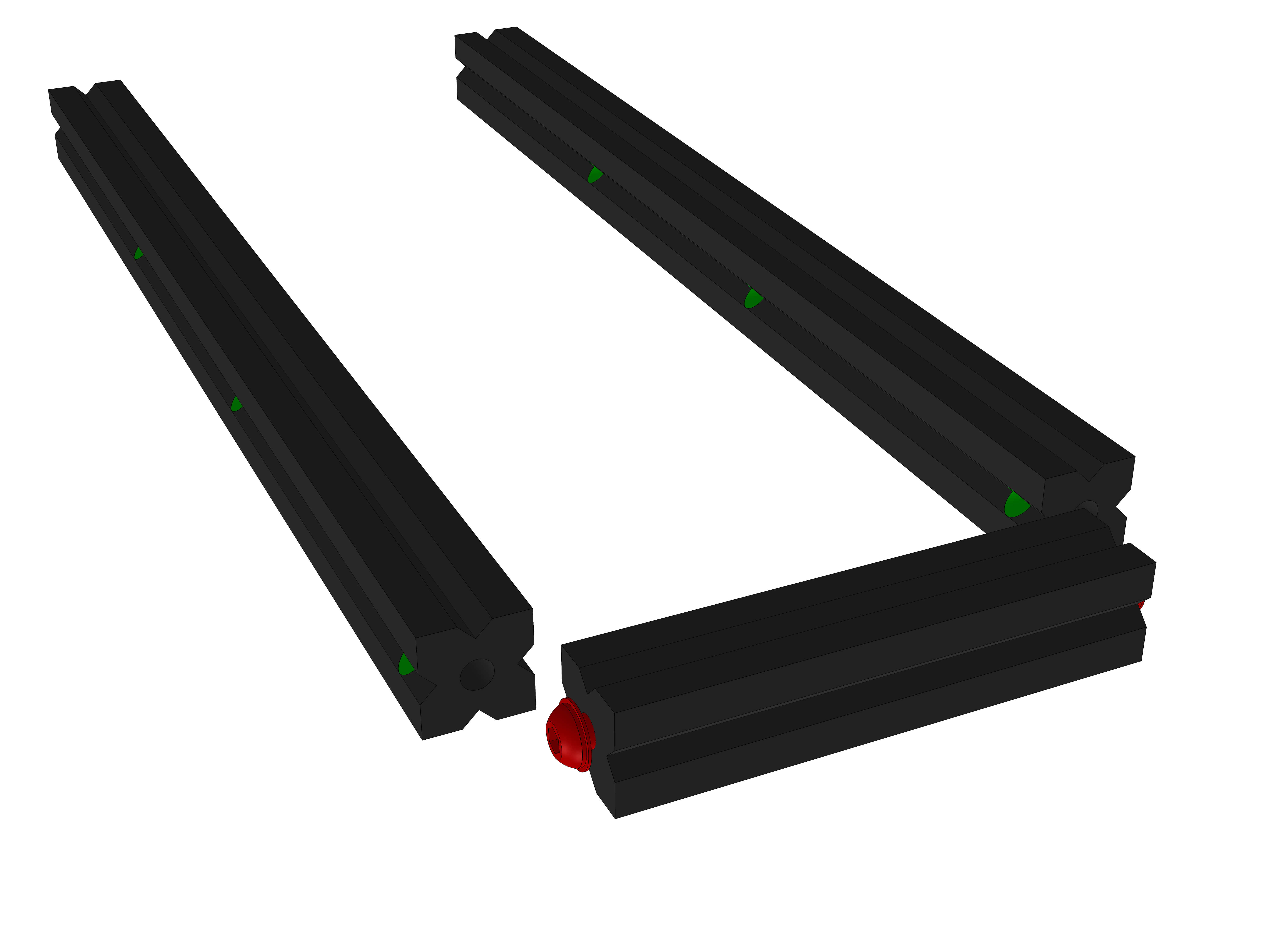
(If using blindjoints) Attach two M5/M6 bolts to the 100mm extrusion.
Attach the 100mm extrusion to the 300mm extrusion as shown, note the location of the drill holes. Don't tighten the screws yet.
Parts:
- Top_Plate_1
Hardware:
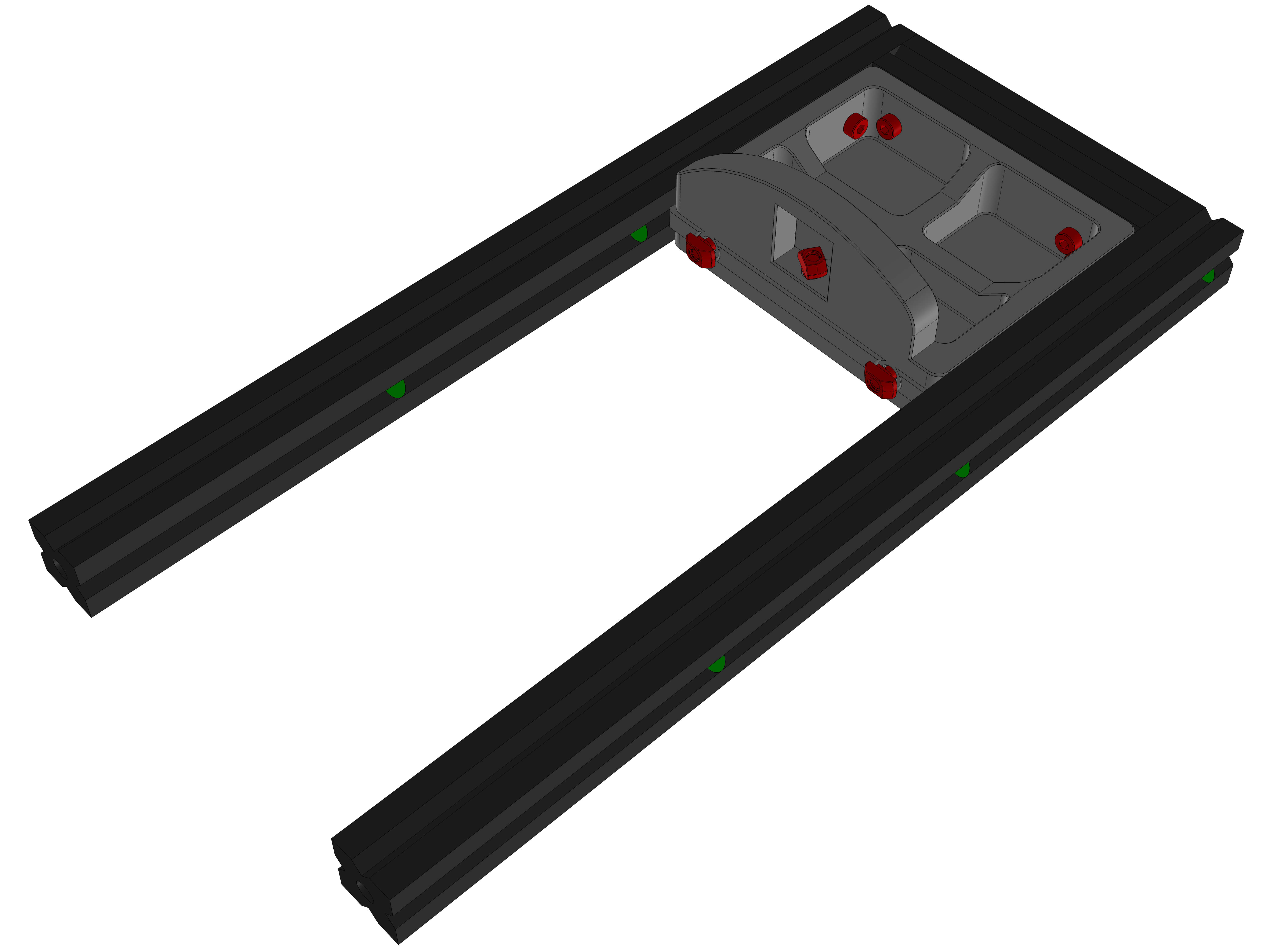
- M4x12 screws (9)
- M4 T-nuts (9)
Attach the M4x12 screws and T-nuts to the Top_Plate_1. Attach it as shown to the extrusion assembly. You might need an extra extrusion for alignment.
Tighten all M4 screws to torque 4, then tighten the two M5/M6 bolts to torque 5.
Hardware:
- 2020: 100mm (EX-G)
- M5/6x12 buttonhead screws (2)
Attach another 100mm extrusion (with M5/M6 bolts) as shown.
First tighten the M4 screws to torque 4, then the bolts to torque 5.
Parts:
- Top_Plate_2
Hardware:
- 2020: 100mm (EX-G)
- M4x12 screws (8)
- M4 T-nuts (8)
- M5/6x12 buttonhead screws (2)
Attach the M4x12 screws and T-nuts to the Top_Plate and M5/M6 bolts to the 100mm extrusion.
Slide them in as shown. Like in the previous steps, tighten the M4 screws first, then the M5/M6 bolts.
Parts:
- UFC_adapter (4)
Hardware:
- UCF206 bearing
- M5x20 screws (4)
- M5 T-nuts (4)
- M6 washers (4)
Prepare the UCF206 bearing with UCF_adapter, M5x20, M6 washer and T-nuts like earlier.
Place it on the two 100mm extrusions with the grease input facing away from the Top_Plate and the rear side touching the protrusion of the Top_Plate.
Make sure it is centered, then carefully tighten the M5 screws while making sure the bearing doesnt move.
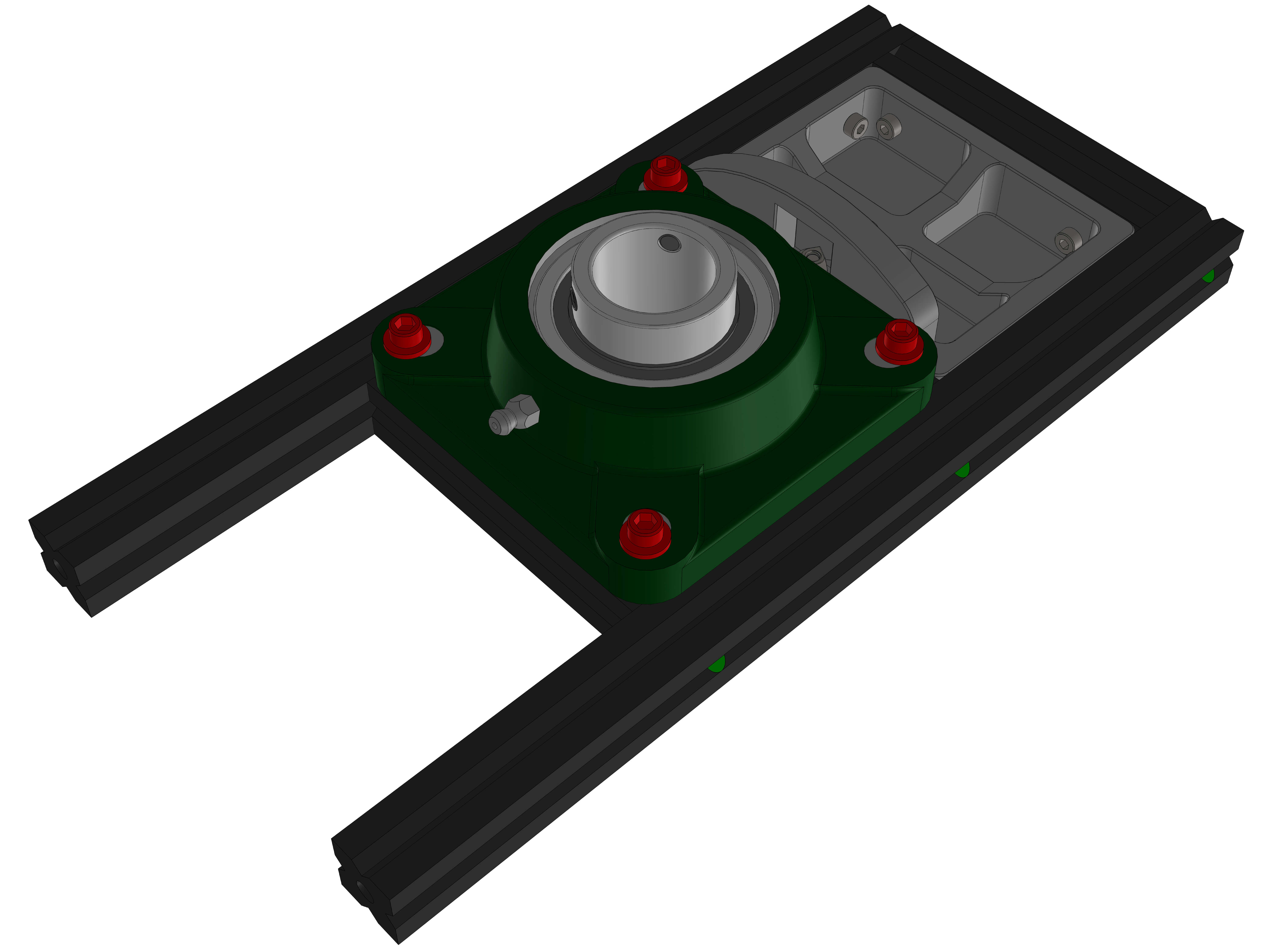
Parts:
- 20x80x120
Hardware:
- M4x12 screws (4)
- M4 T-nuts (4)
Attach the M4x12 screws and T-nuts to the part. Attach it as shown to the assembly.
This part has mounts for custom addons. See the specifications to mount your own things to OAM
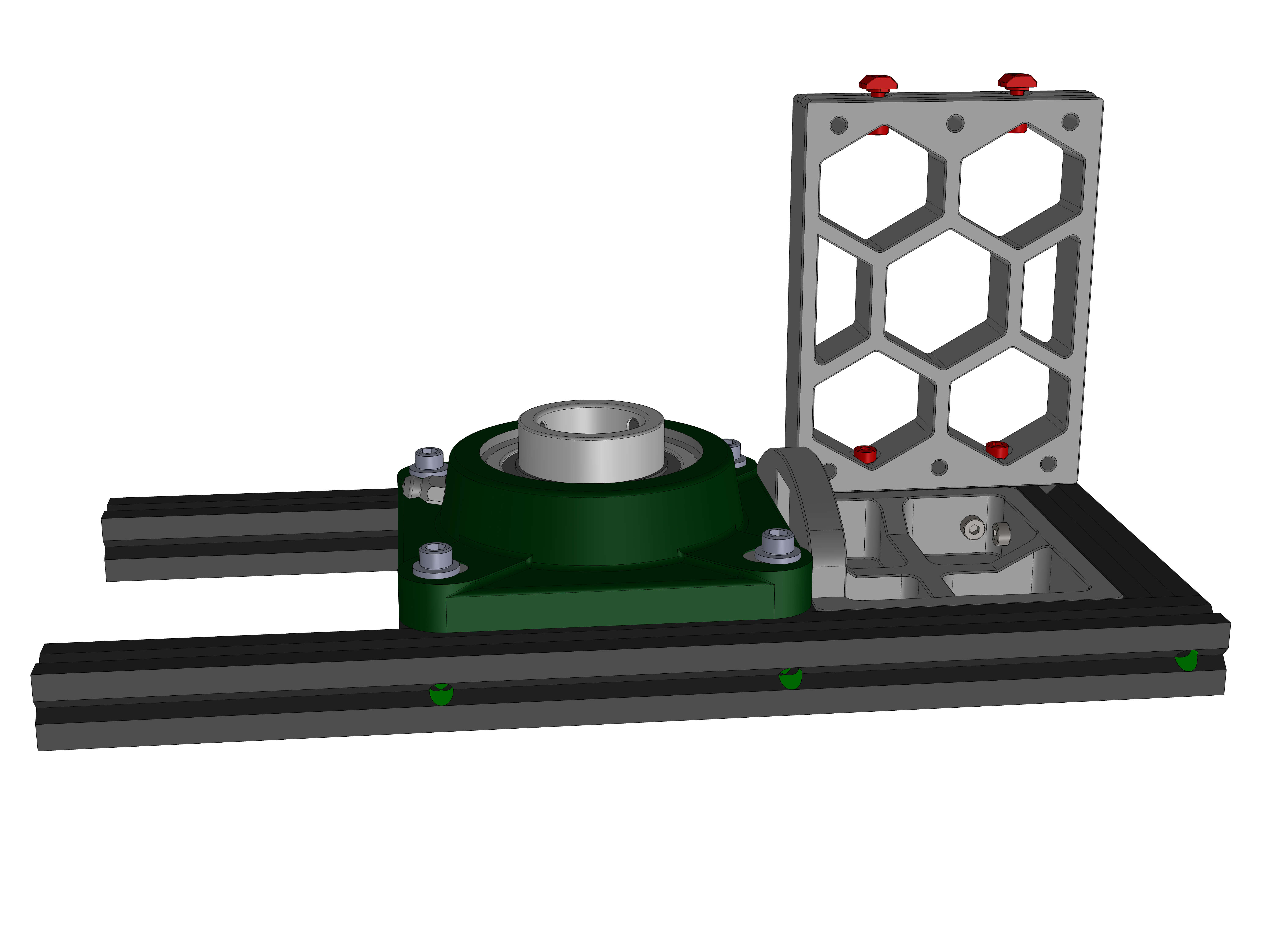
(If using blindjoints) Attach two M5/M6 bolts to the front of the 300mm extrusions, then slide the assembly on as shown.
Tighten the two screws on the 20x80x120 part, then tighten the two M5/M6 bolts.
Untighten the two screws on the 20x80x120 part to release any tension that might have build from tightening the M5/M6 bolts, then tighten them again.
Parts:
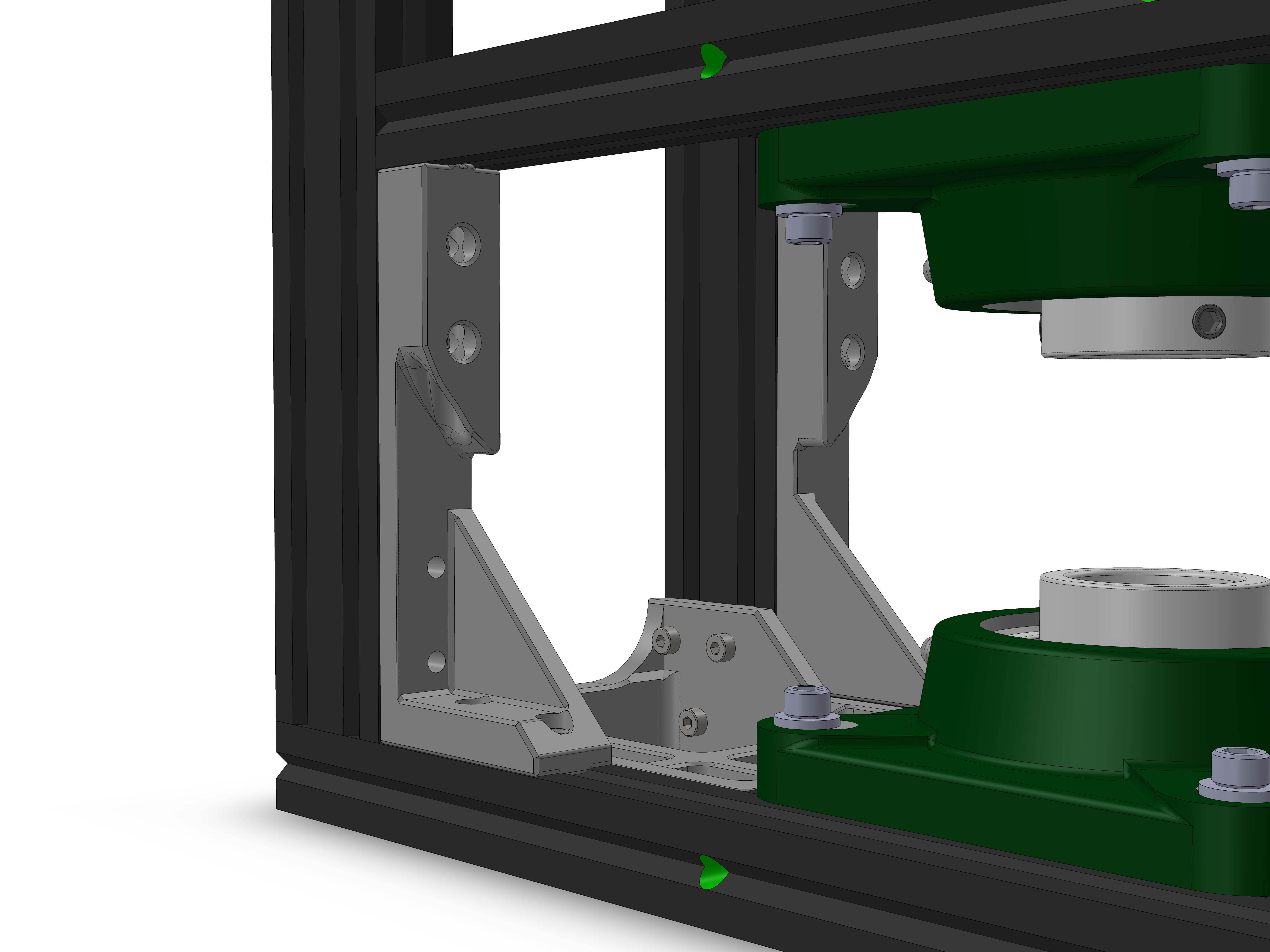
- Frame_bracing_left
- Frame_bracing_right
This step is only necessary when NOT using blindjoints.
Before tightening the 20x80x120 part, attach the Frame_braces with M4x12 and T-nuts as shown.
Parts:
- DEC_holder_1
- DEC_holder_2
Hardware:
- M4x12 screws (4)
- M4 T-nuts (4)
- M3x12 screws (2)
- M3 inserts (2)
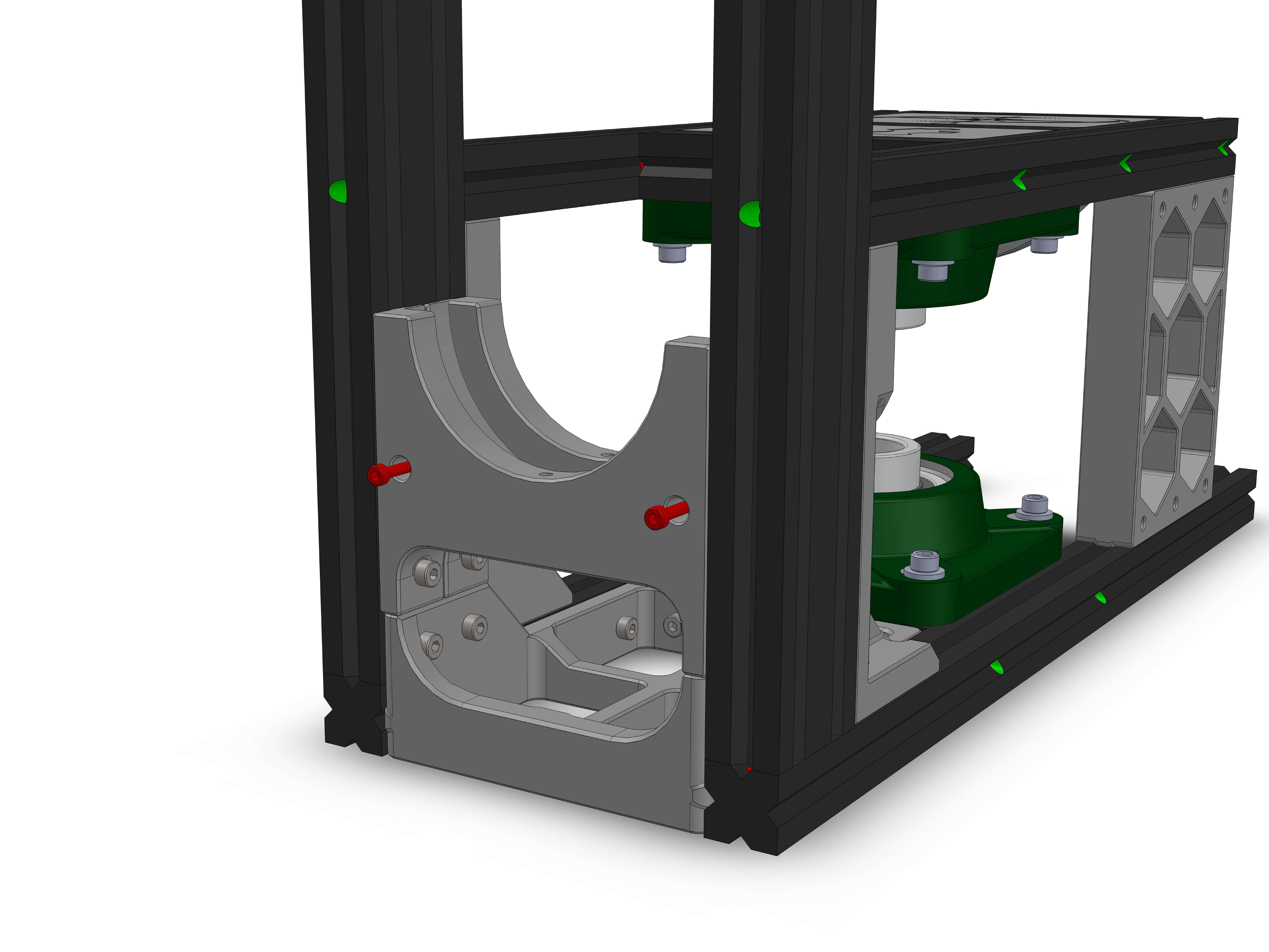
Insert the M3 inserts into the DEC holder that does not have through holes. Insert two M4 screws and T-nuts into the sides of each of the DEC holders
Attach the DEC_holders as shown. The one that has inserts in it goes in the rear, but with the inserts facing the front.
The other one should have the thin section of the through holes facing the inserts.
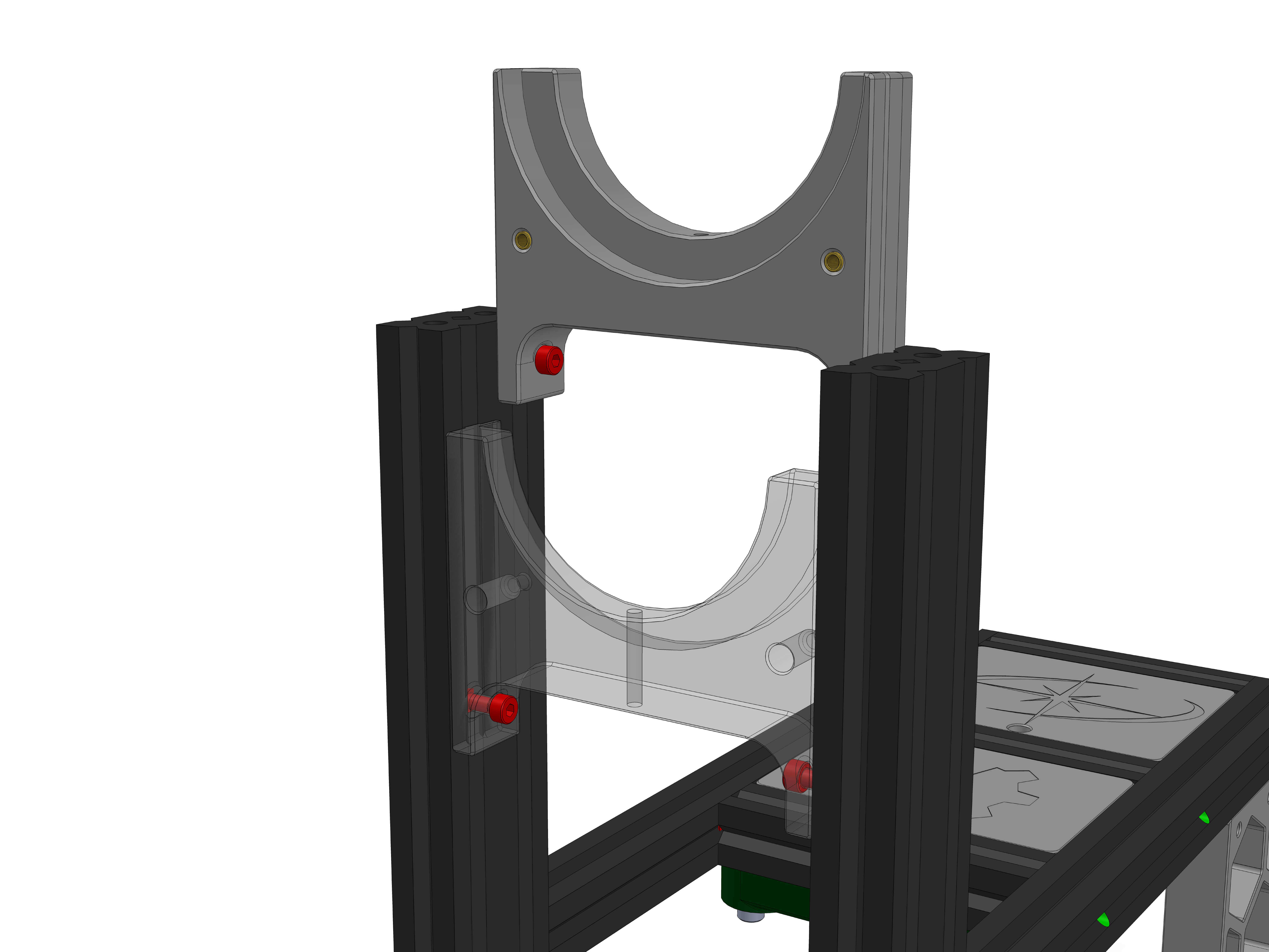
Slide the two parts all the way down until it rests on the bottom parts.
Insert two M3x12 into the through holes but do not tighten them yet. If they don't disappear in the part, you have mounted it the wrong way around.
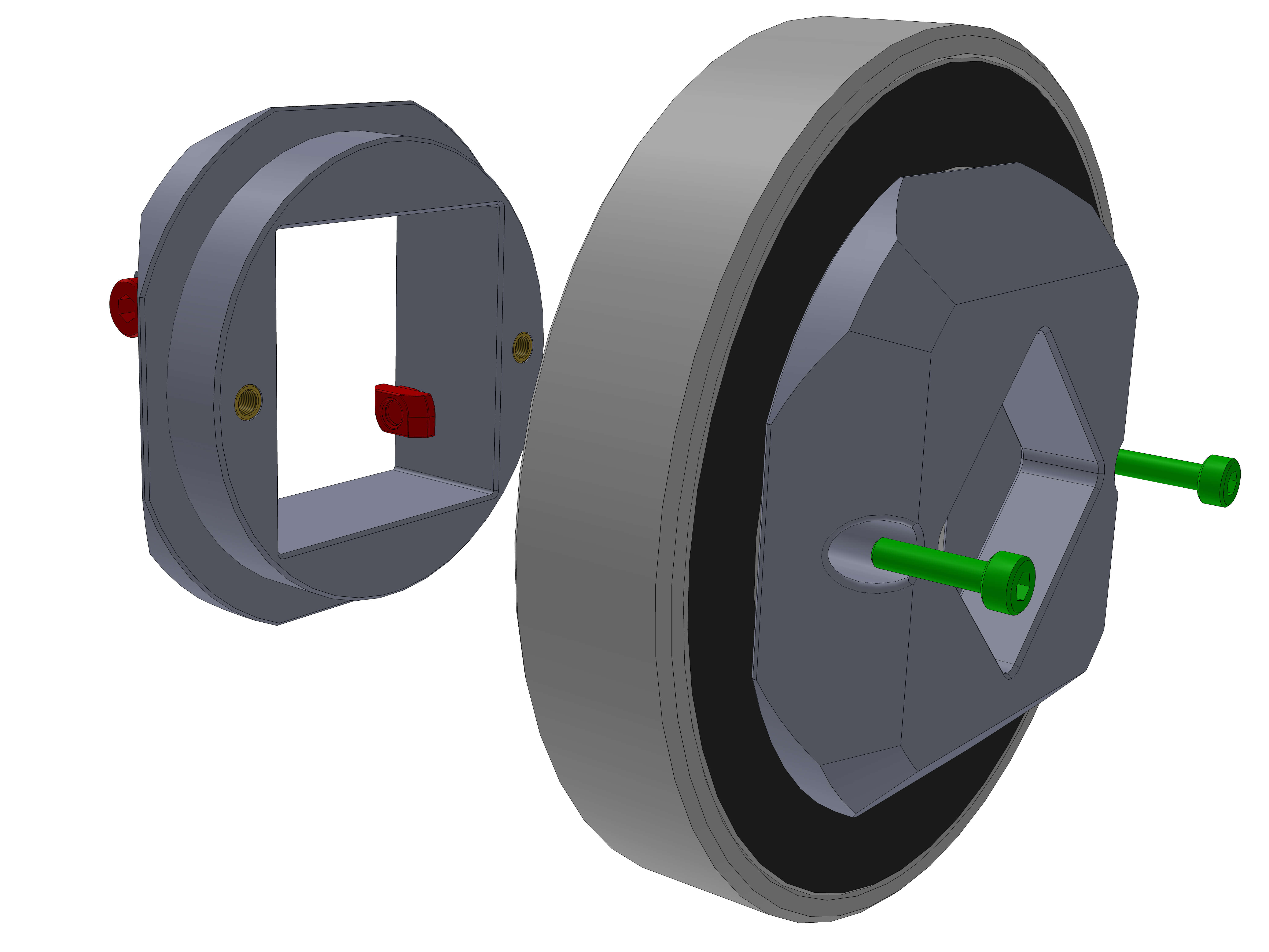
Parts:
- 4040_adapter_rear
- 4040_adapter_mid
Hardware:
- 6012 bearing
- M4x12 screws (2)
- M4 T-nuts (2)
- M3 inserts (2)
- M3x12 screws (2)
Insert the two M3 inserts into the 4040_adapter_mid part. Then attach two M4x12 & T-nuts to it. Place the bearing on the adapter_mid part and then push the adapter_rear part onto it, making sure the through holes align with the inserts. Then insert two M3x12 screws and tighten them to torque 3.
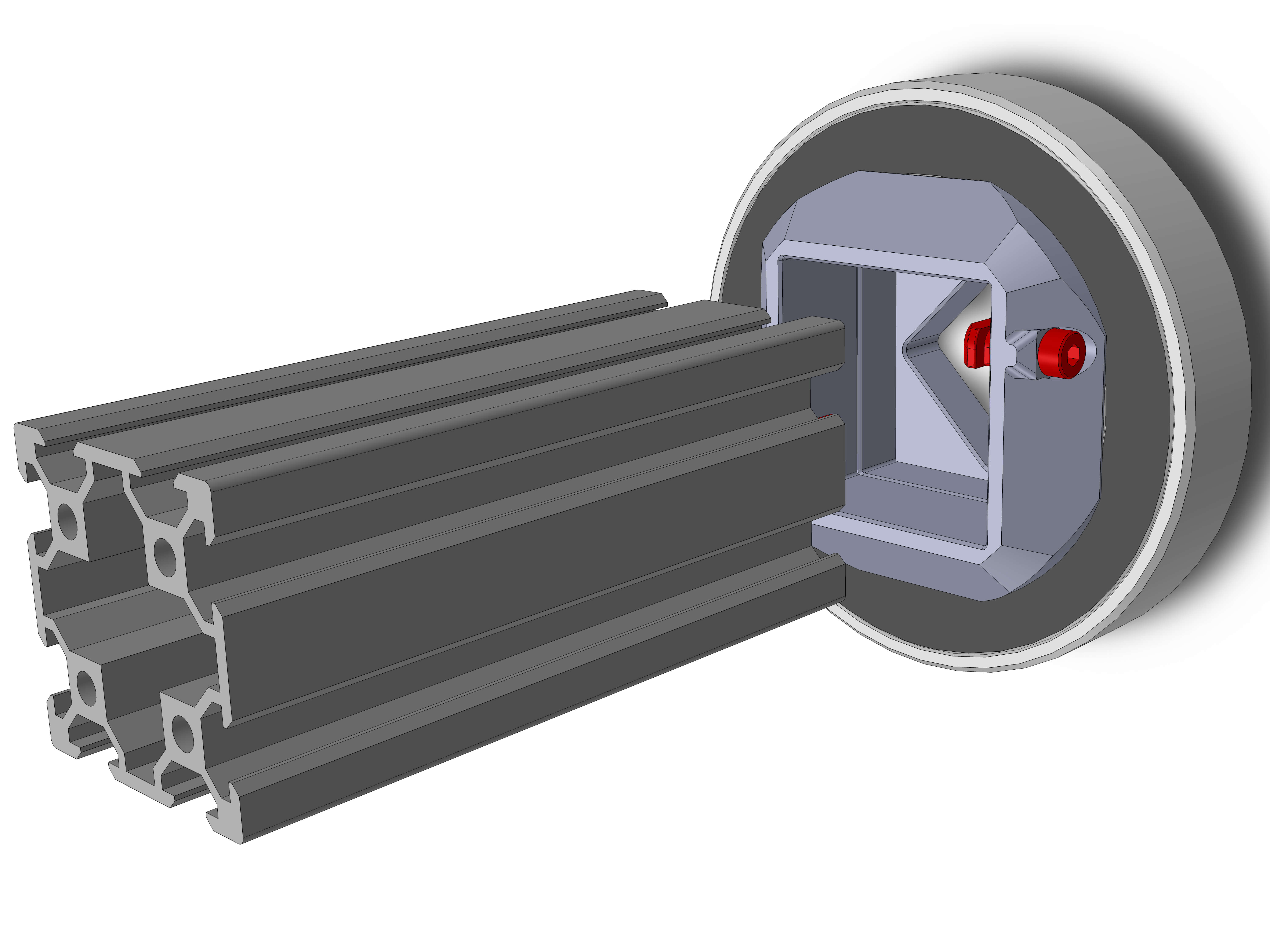
Hardware:
- 4040: 100mm
Insert the 4040 extrusion. This might take some force. Make sure its inserted all the way, then tighten the M4 screws to torque 3.
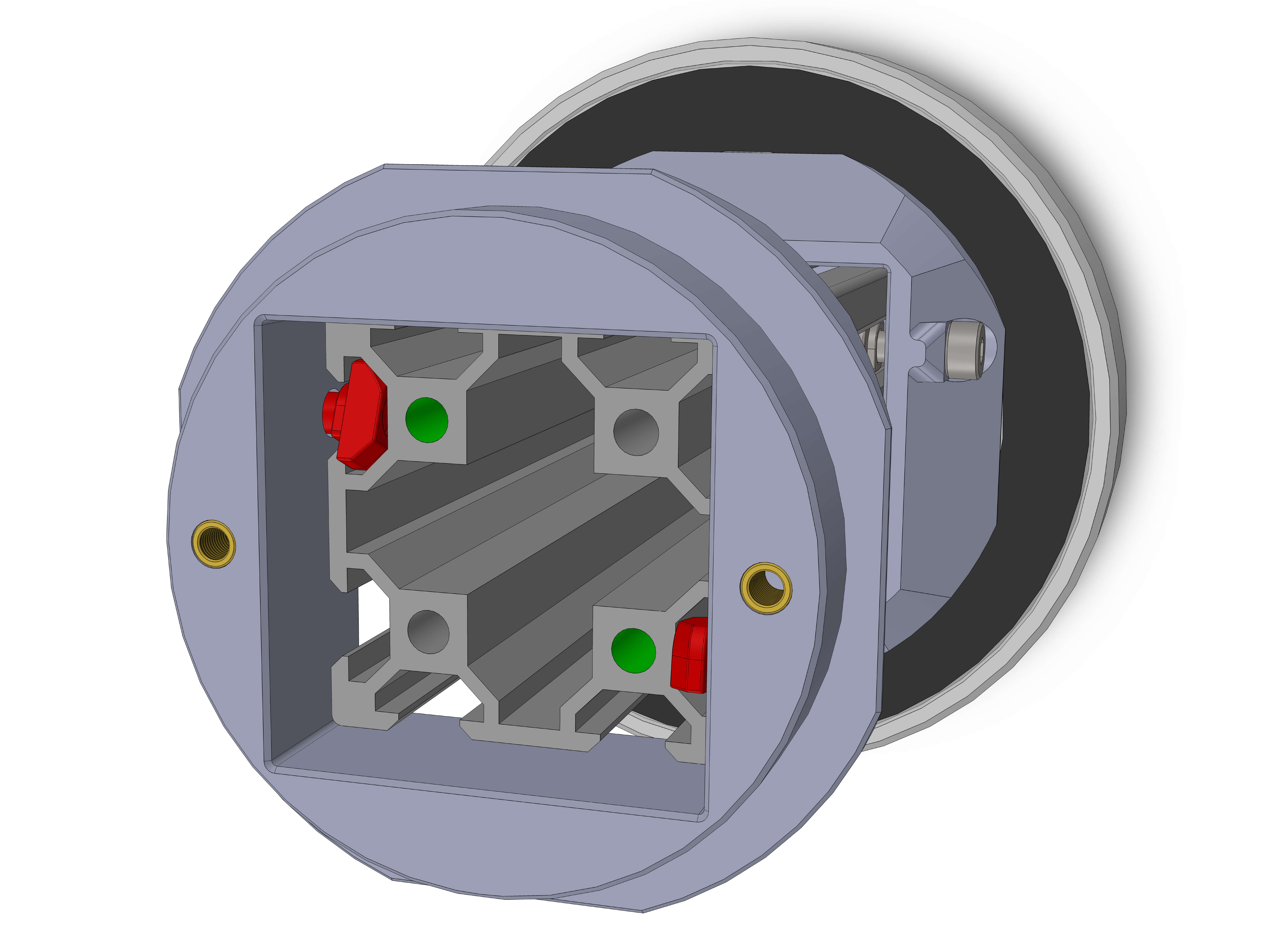
Parts:
- 4040_adapter_mid
Hardware:
- M3 inserts (2)
- M4x12 screws (2)
- M4 T-nuts (2)
Attach the other 4040_adapter_mid. Note the orientation of the threads (green) to the inserts.
Parts:
- 4040_adapter_front
Hardware:
- 6012 bearing
- M3 inserts (4)
- M4x12 screws (2)
- M4 T-nuts (2)
- M3x12 screws (2)
Insert the four M3 inserts into the adapter. Attach the two M4x12 screws and T-nuts.
Attach the bearing, then place the 4040_adapter_front, making sure the through holes align with the inserts, then use two M3x12 screws to fasten the two parts together. Tighten to torque 3.
Do not tighten the M4 screws yet. The part should be able to slide on the extrusion (might require a little force). Make the extrusion stick out a little bit.
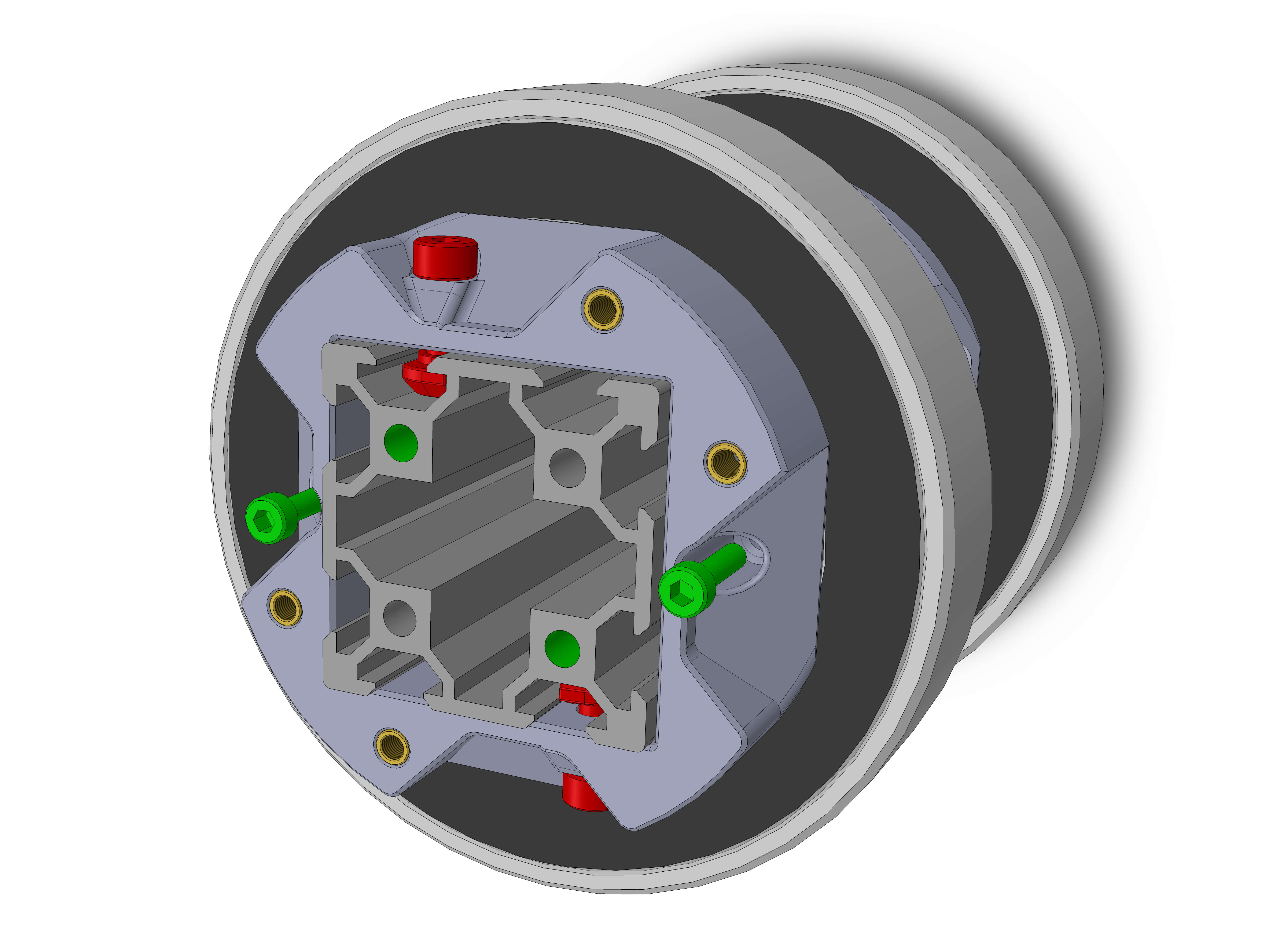
Parts:
- DEC_wheel_2.3
Hardware:
- 2020: 200mm (EX-A)
- M4x12 screws (2)
- M4 T-nuts (2)
- M3 inserts (1)
Attach two M4x12 and T-nuts to the extrusion as shown. Attach the DEC_wheel part and make sure the DEC wheel slot is aligned with the end of the extrusion.
Insert the M3 inserts on the left edge and in the belt depression.
Tighten the M4 screws, but push both parts to a flat surface to prevent them from moving.
Parts:
- DEC_wheel_1
Hardware:
- M4x12 screws (2)
- M4 T-nuts (2)
- M3 inserts (7)
Insert the M3 inserts into the edges of the part.
Attach two M4x12 and T-nuts to the DEC_wheel_1 and attach it to the extrusion.
If you want to route some cables to the RIGHT side of the DEC wheel, insert them now as shown. A USB extension cord would be a good candidate.
Slide the two parts together and use two M3x12 screws (green) to screw them together. Then tighten the two M4 screws to torque 3.
Make sure that the two holes in the extrusion are oriented vertically
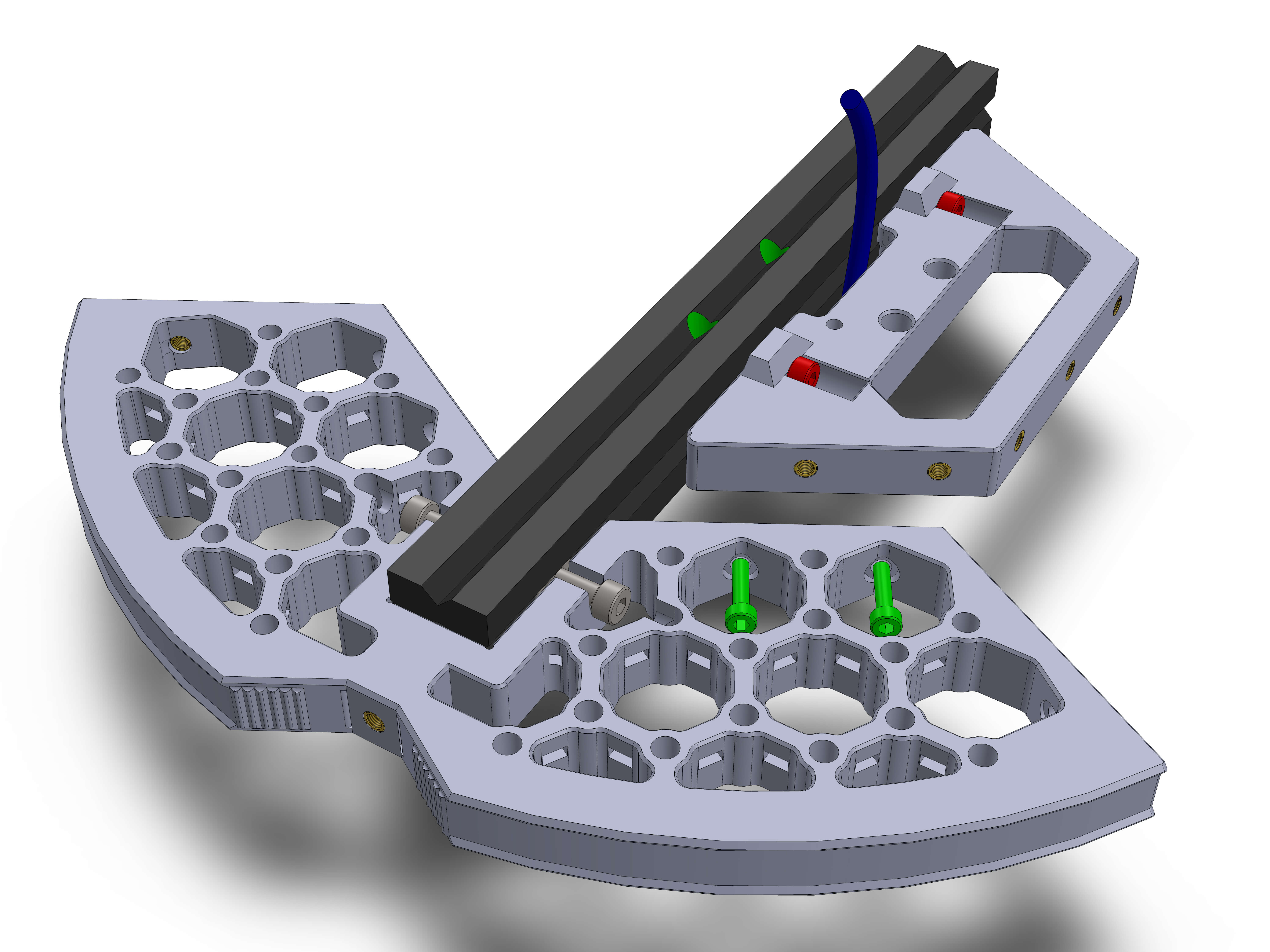
Hardware:
- M5x20 flathead screws (2)
Take two M5x20 flathead screws and slide them in the extrusion slot on the bottom side of the assembly.
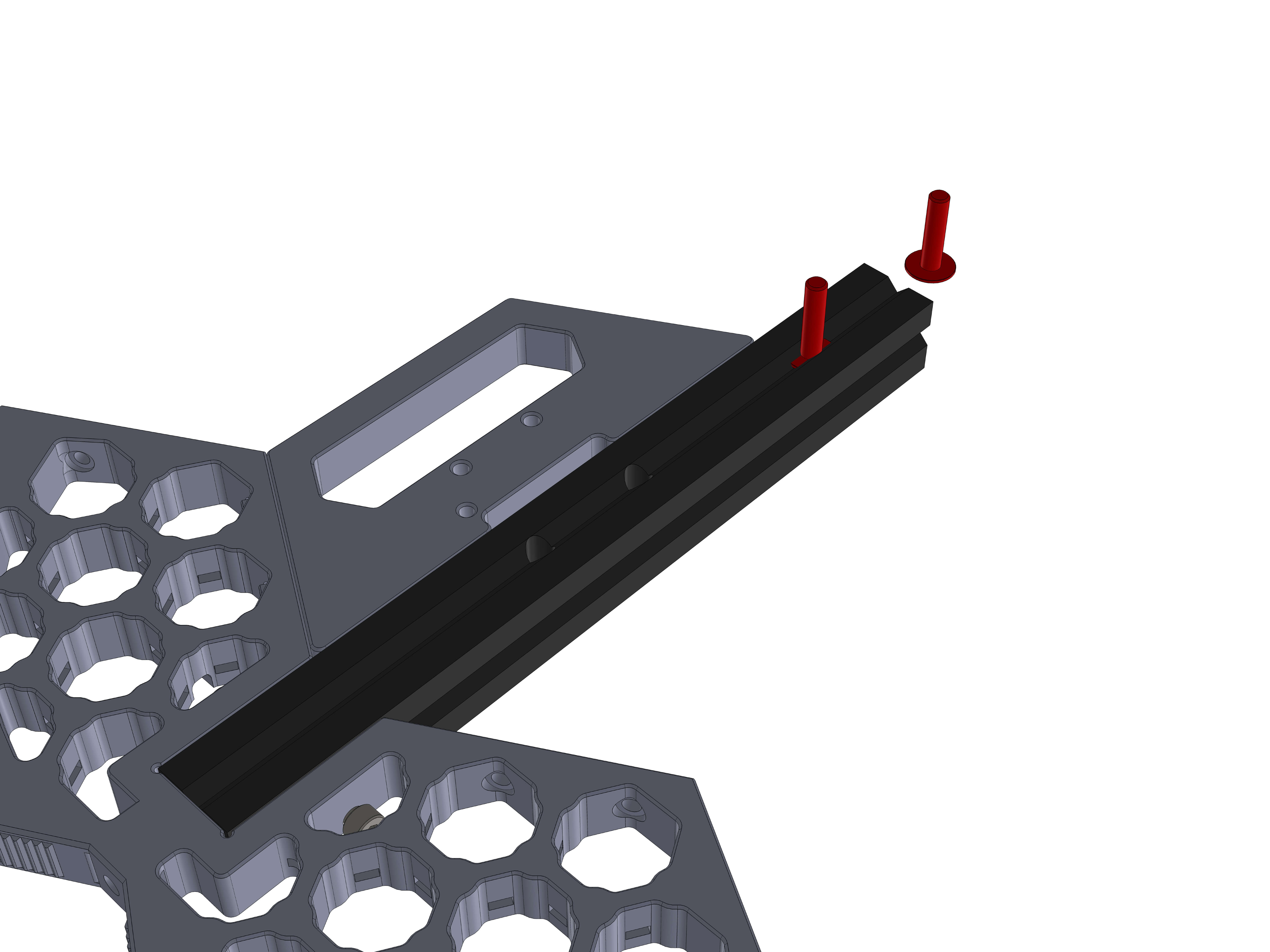
Parts:
- DEC_wheel_2.1
Hardware:
- M3 insert
- M4x12 screw
- M4 T-nut
- M3x12 screws (6)
Insert the M3 inserts into the DEC_wheel_2.1 part where the green screw connects it to the existing assembly.
Then attach a M4x12 screw and T-nut to the extrusion and attach the DEC wheel part like the earlier step. Use six M3x12 screws to attach it.
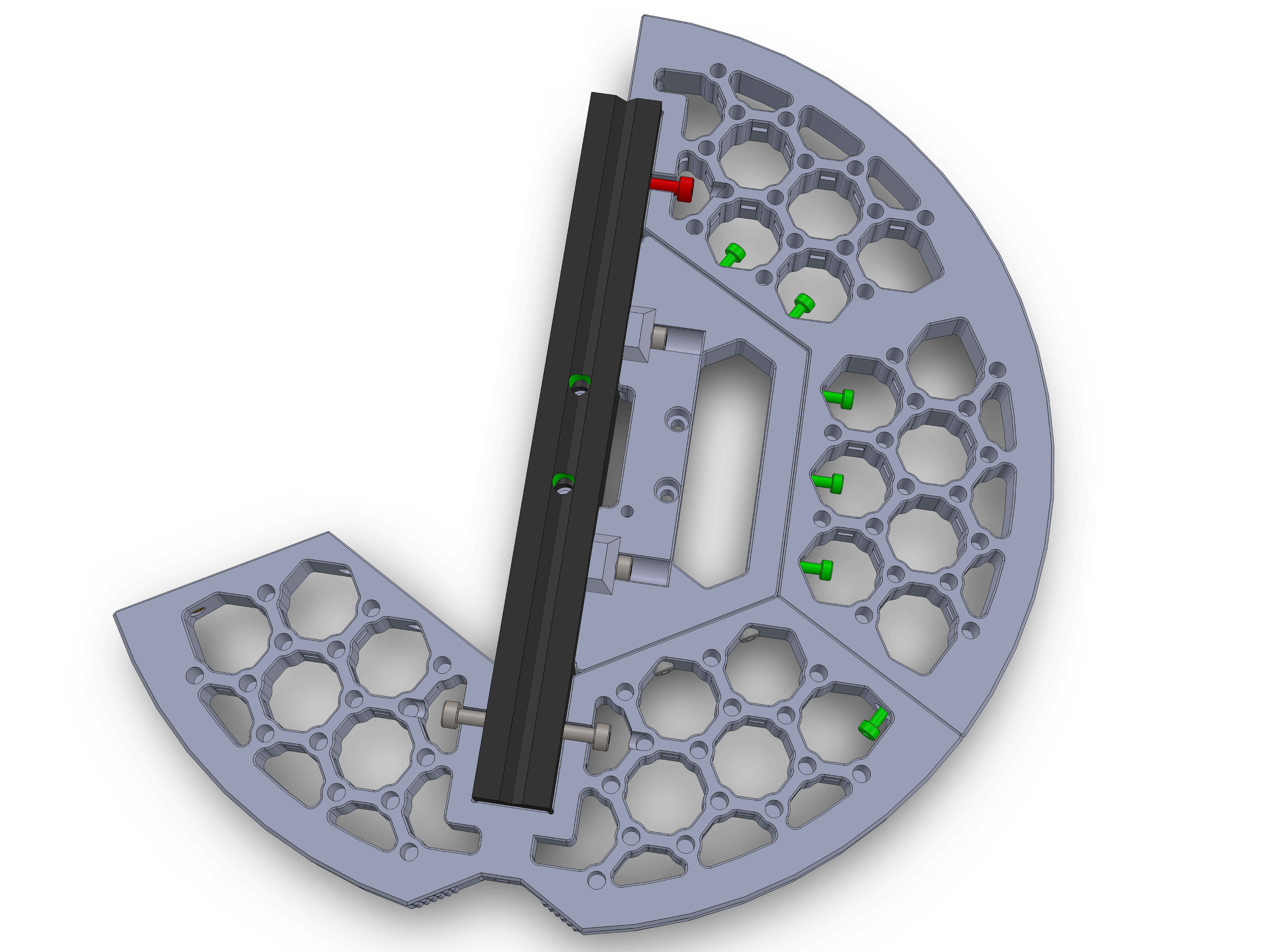
Parts:
- DEC_wheel_1
Hardware:
- M4x12 screws (2)
- M4 T-nuts (2)
- M3x12 screws (2)
Attach the remaining DEC_wheel_1 like the previous one.
If you want to route some cables to the LEFT side of the DEC wheel, insert them now.
Attach two M3x12 screws (green) and tighten them first, then tighten the M4 screws.
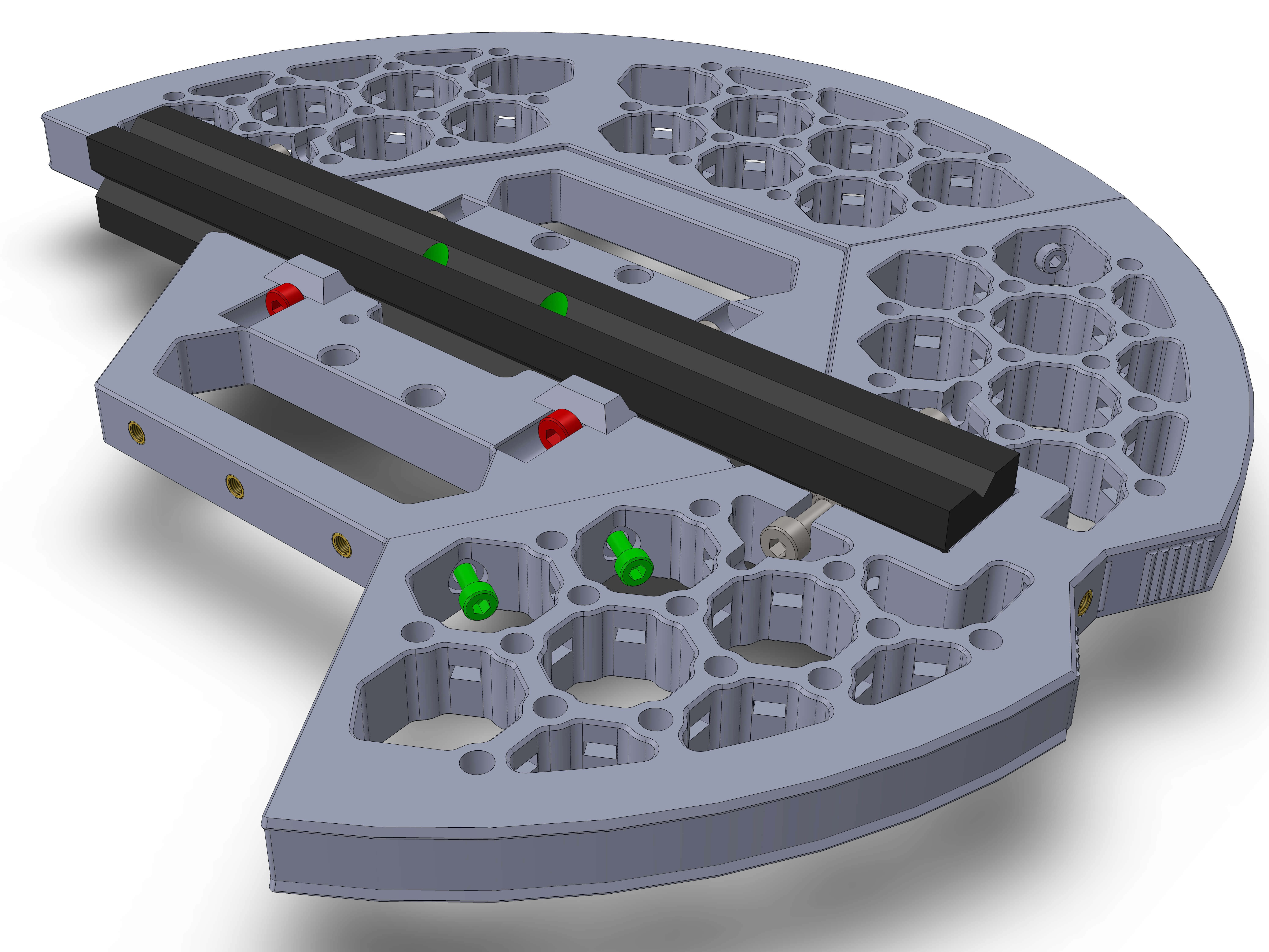
Part:
- DEC_wheel_2.2
Hardware:
- M4x12 screw
- M4 T-nut
- M3x12 screws (7)
- M3 insert
Like the previous DEC_wheel_2.1, attach a M4x12 and TNut, then use 6 M3x12 screws to screw the part to the others.
The DEC wheel has mounts for custom addons. See the specifications to mount your own things to it
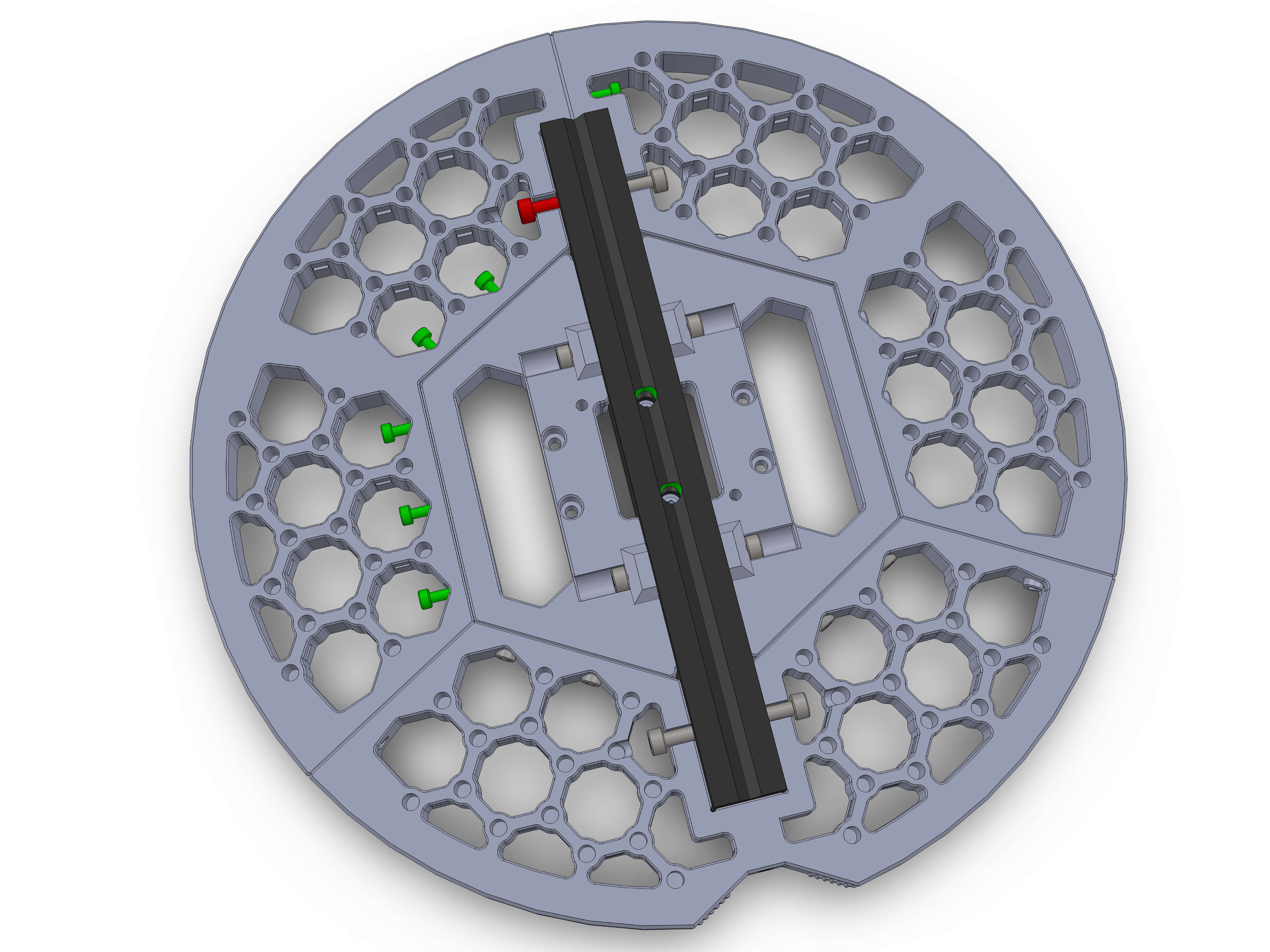
Hardware:
- M4x12 screws (2)
- M4 T-nuts (2)
- M3x12 screws (4)
Attach the 4040 assembly to the DEC wheel as shown. If you have any cables, route them through the 4040 extrusion.
The threads in the 4040 extrusion should align with the drill holes in the 2020 extrusion.
Bring the M5x20 screws in position, then screw them in in an alternating fashion to prevent them from binding. Dont tighten them yet, the extrusion should still be able to move slightly.
Insert 4 M3x12 screws (green) into the DEC_wheel_1 parts as shown and tighten them. They should now pull the 4040_adapter towards the DEC wheel and align it.
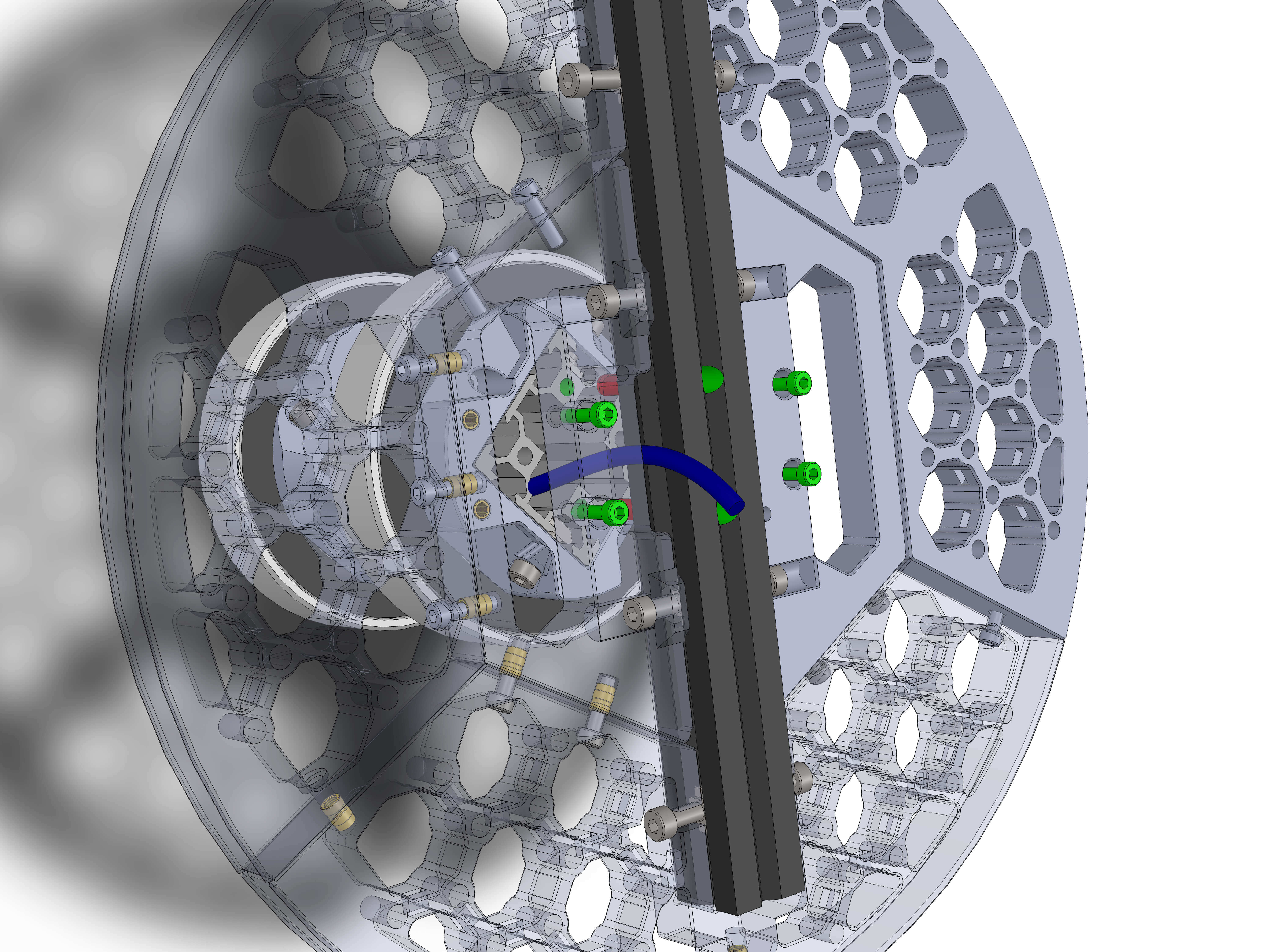
If the 4040_adapter sits flush to the DEC wheel, tighten the two M5x20 screws to torque 5.
Regardless of whether or not you used blindjoints for the rest of the assembly, you MUST use them here. The weight of your entire scope will rest on this joint and the 4 M3 screws will NOT hold it. They are only used for alignment.
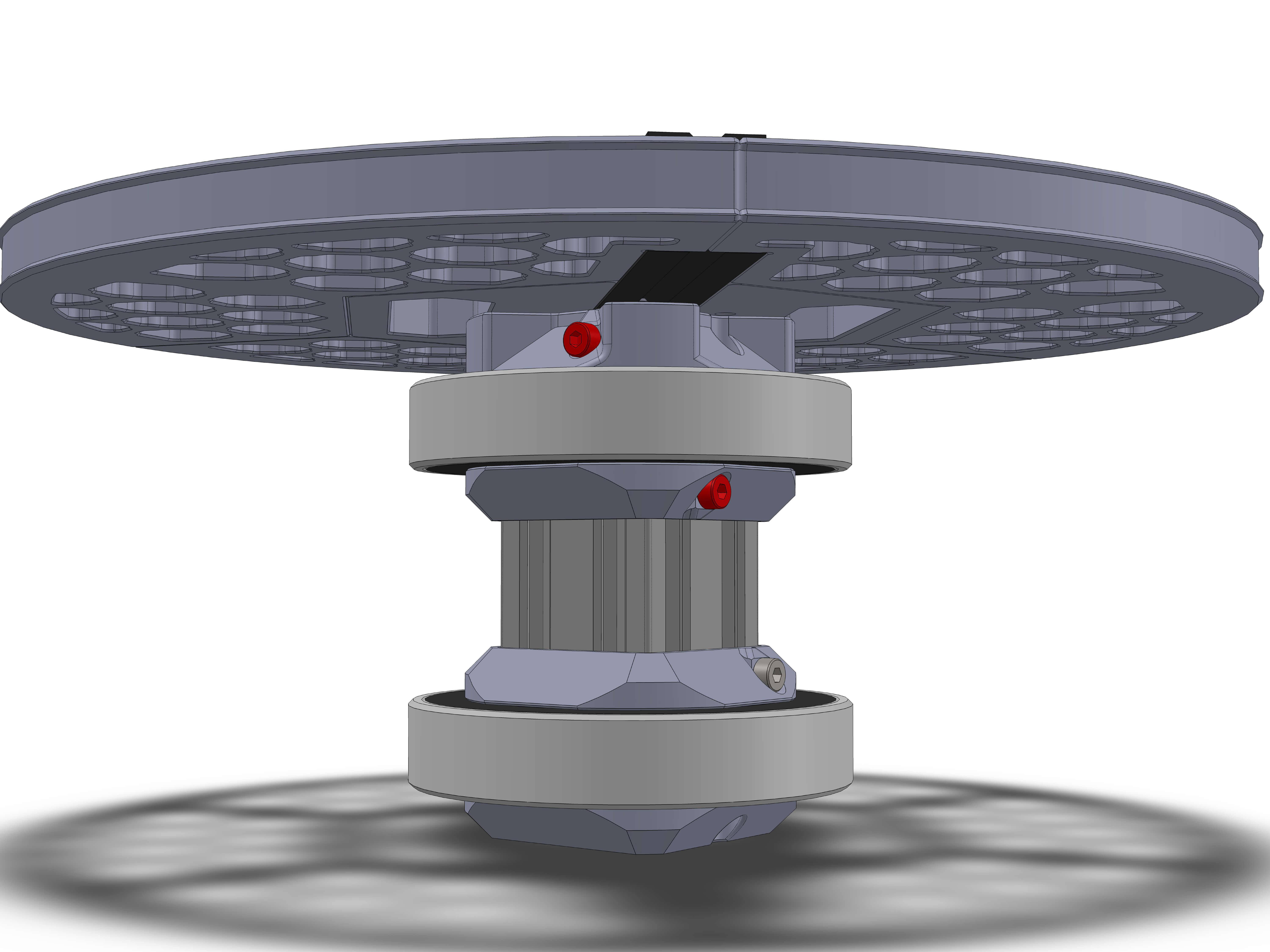
Place the DEC wheel assembly to the previous assembly as shown.
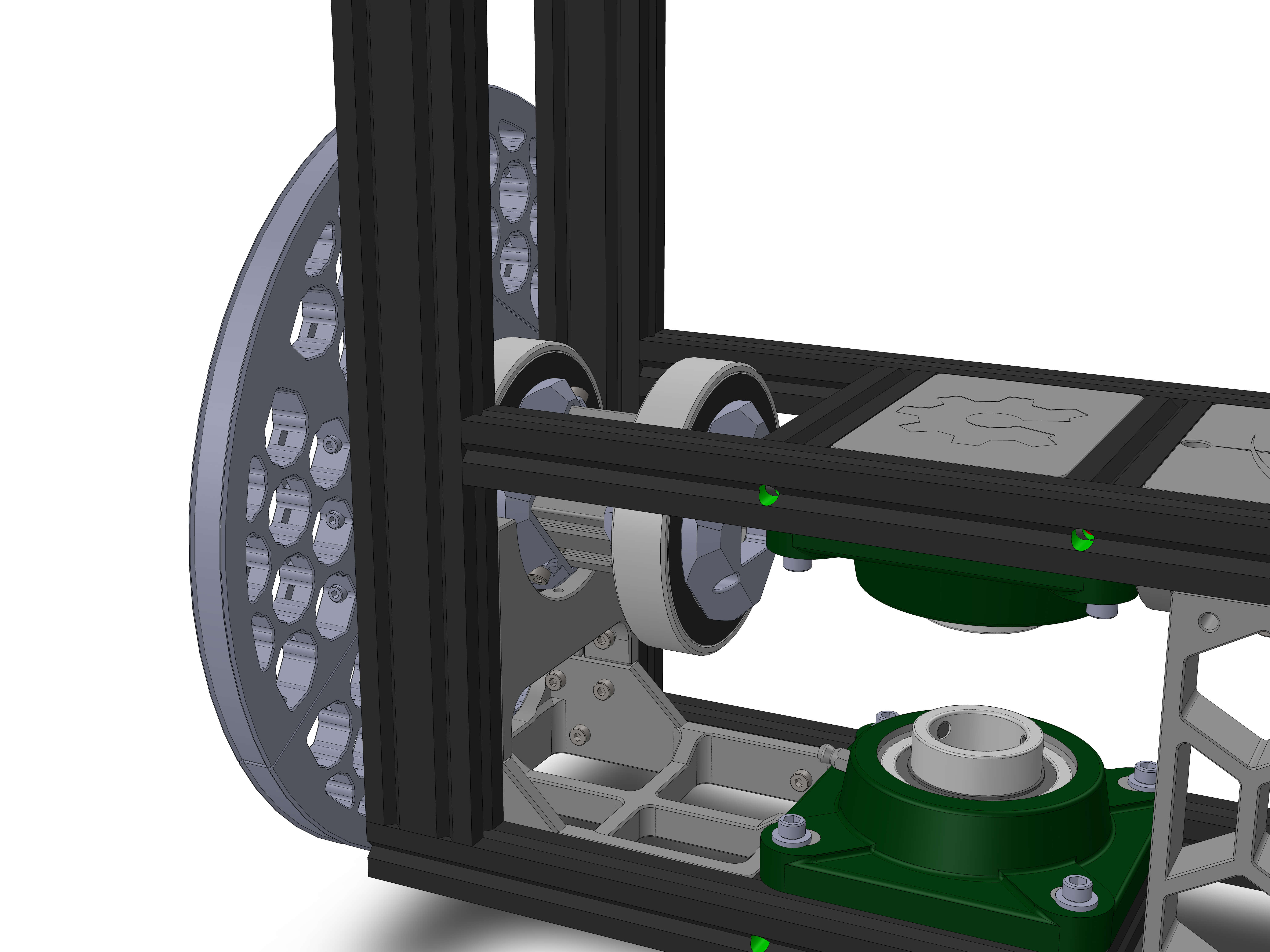
Parts:
- DEC_holder_1
- DEC_holder_2
Hardware:
- M4x12 screws (4)
- M4 T-nuts (4)
- M3 inserts (2)
- M3x12 screws (4)
Insert the M3 inserts into the holder as shown.
Attach M4x12 and T-nuts to the DEC_holders and attach them as shown. Note their orientation, it is the same as earlier.
Slide them all the way to the bottom, and tighten the M4 screws while gently pushing the parts down onto the 6012 bearing.
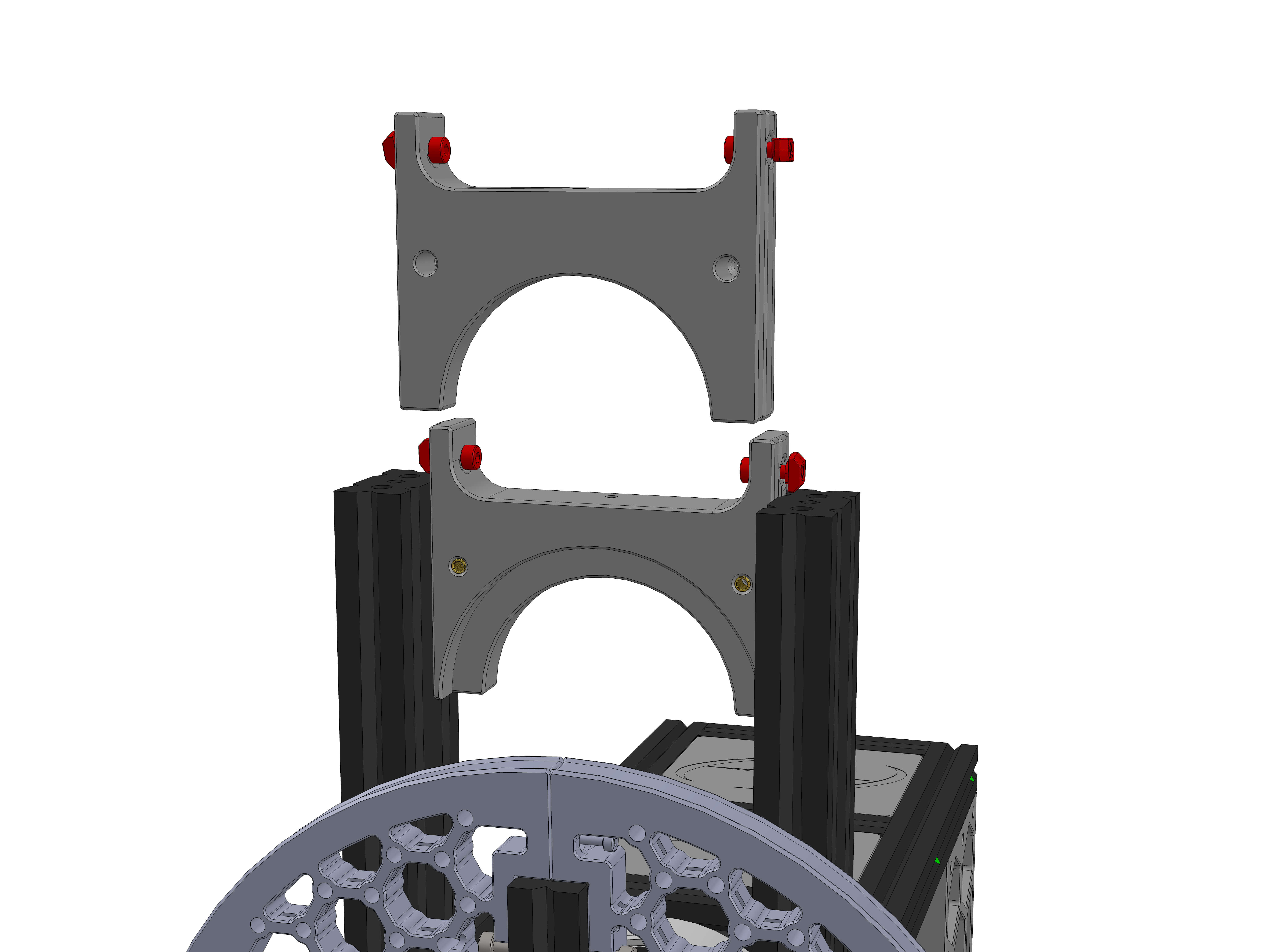
Rotate the DEC wheel to access the holes for the M3 screws. Insert two at the top, then tighten all of them to torque 3. There are a total of 4 M3 screws to tighten.
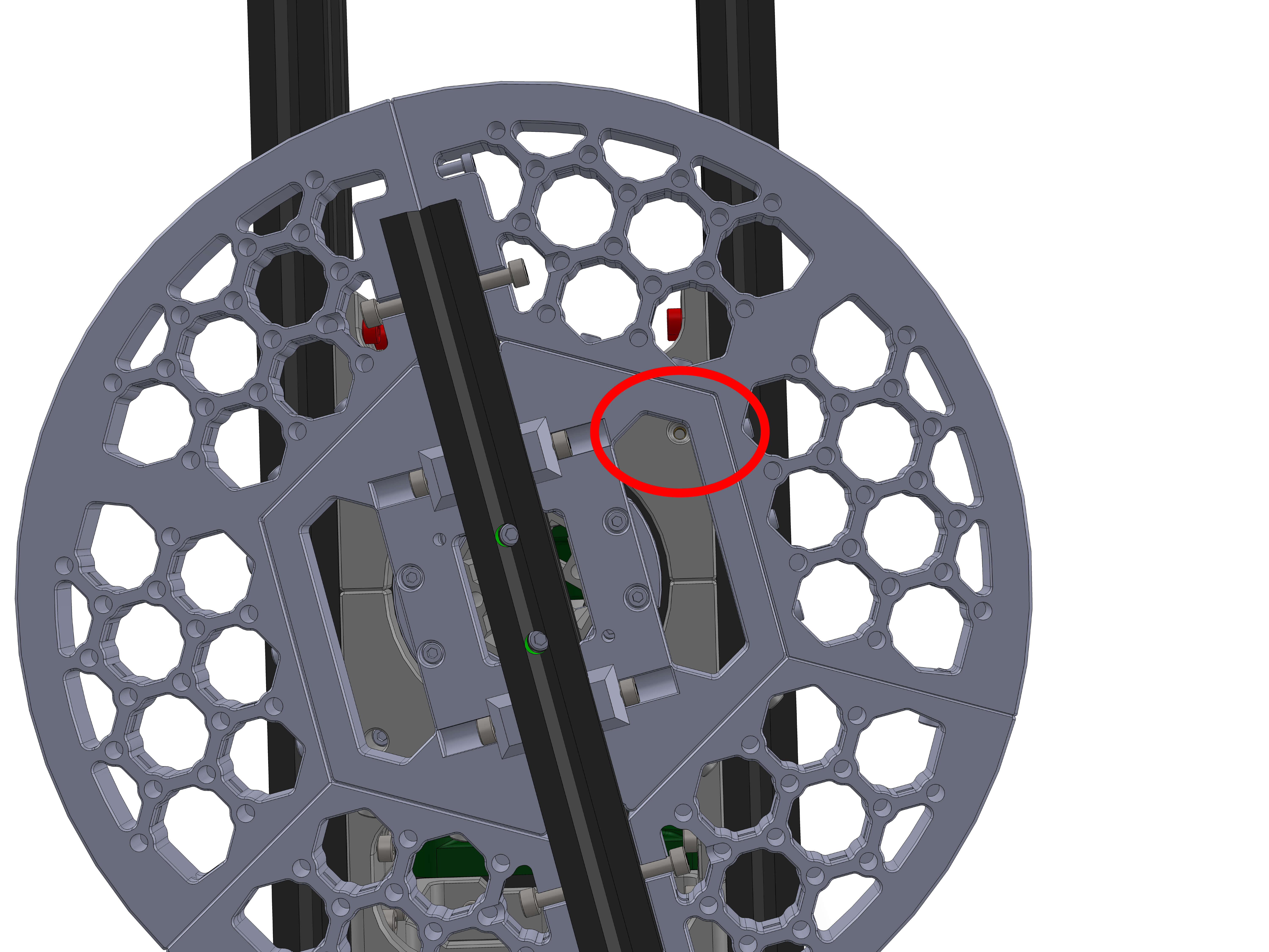
Parts:
- DEC_bearingHolder_front_bottom (The one that has insert holes)
Hardware:
- M4x12 screws (2)
- M4 T-nuts (4)
- M3 inserts (2)
Insert the M3 inserts into the holes, two at the side and two at the top.
Attach two M4x12 and T-nuts to the part.
Attach it as shown, but do not tighten the M4 screws yet.
Parts:
- DEC_bearingHolder_rear_bottom (The one that has through holes)
Hardware:
- M3 inserts(2)
- M4x12 screws (2)
- M4 T-nuts (2)
- M3x12 screws (2)
Insert the M3 inserts into the holes at the top.
Attach two M4x12 and T-nuts to the part and attach it as shown. Do not tighten the M4 screws yet.
Take two M3x12 screws and insert them into the through holes. Tighten them to torque 3, then tighten the 4 M4 screws to torque 3.
Parts:
- DEC_bearingHolder_rear_top
- DEC_bearingHolder_front_top
Hardware:
- M4x12 screws(4)
- M4 T-nuts (4)
- M3 inserts (2)
Insert the two M3 heat inserts into the side of DEC_bearingHolder_front_top (make sure you're not putting it in through holes, because then you've got the wrong part).
Attach two M3 screws and T-nuts to each part as shown.
Place the part with the heat inserts over the bearing as shown and insert the M3 screws. Tighten the M3s to the bottom plastic case.
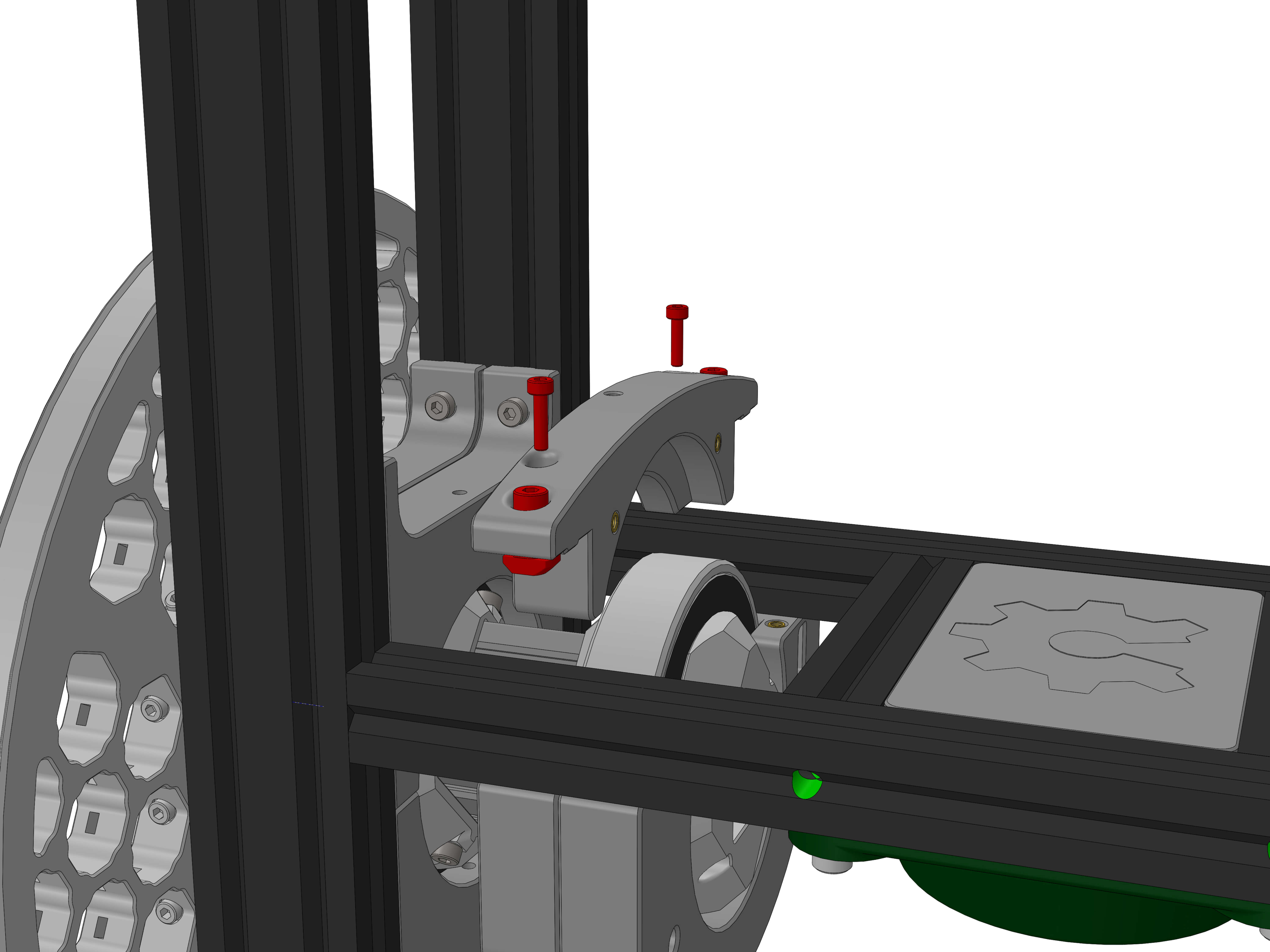
Now place the other part with the through holes over the bearing as shown and screw into the bottom part with two M3x12 screws.
Now insert two M3x12 into the side facing holes and tighten them reasonably tight, but making sure that the DEC wheel still turns freely.
Now tighten the 4 M4 screws with the T-nuts into the extrusion.
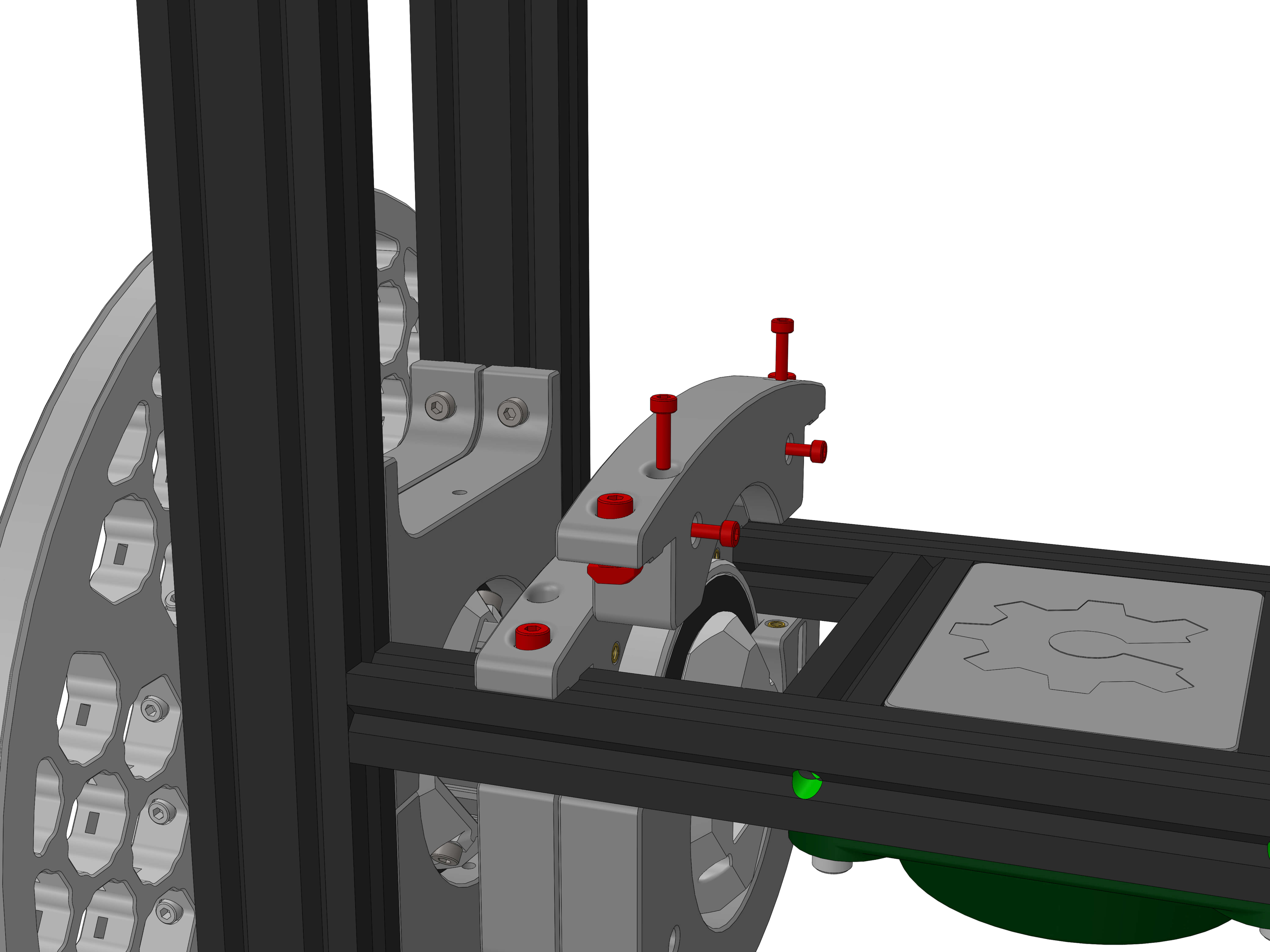
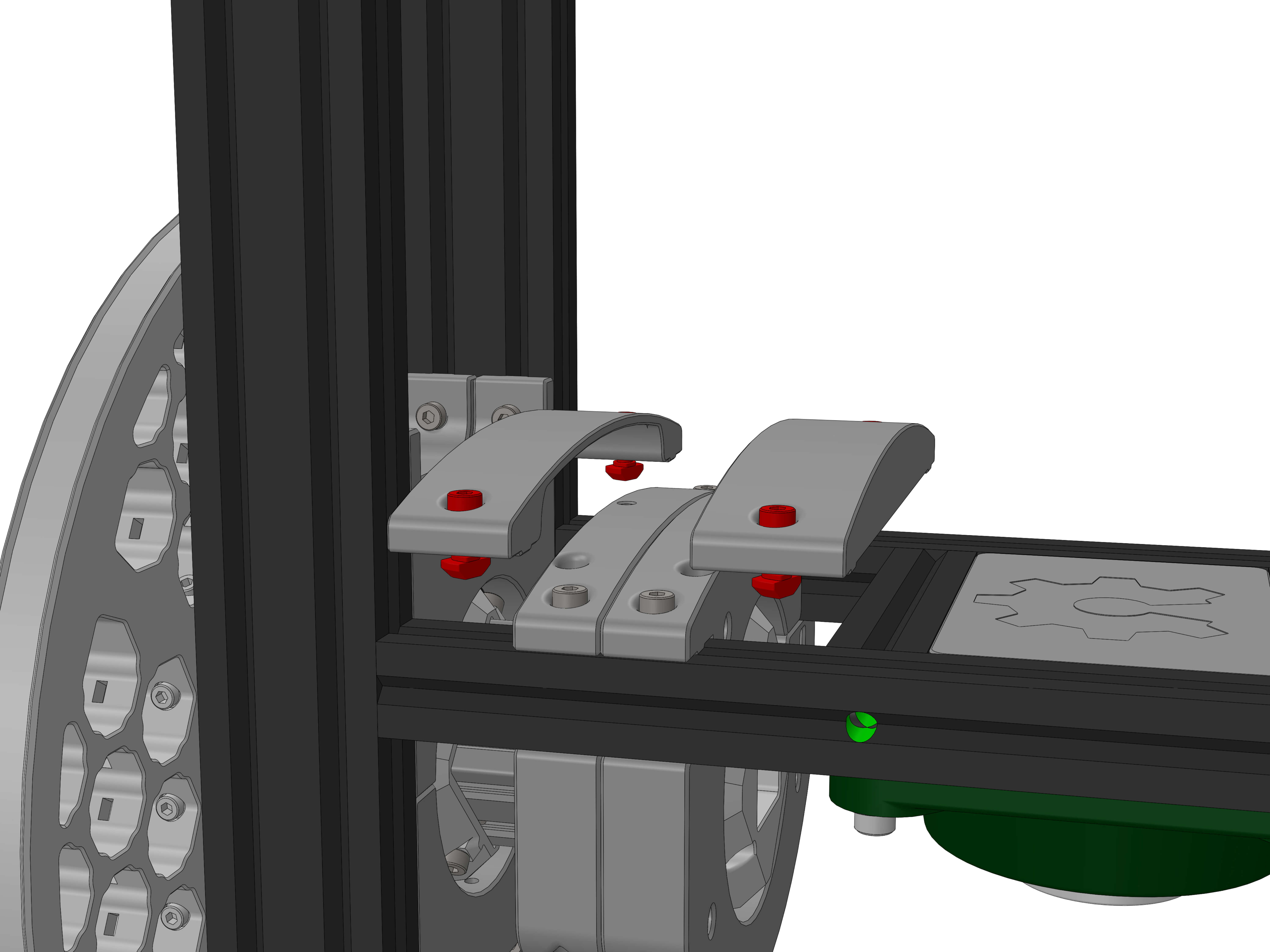
Parts:
- top_cover
- top_cover2
Hardware:
- M4x12 screws (4)
- M4 T-nuts (4)
Insert screws and T-nuts as shown.
Place top_cover2 close to the vertical extrusion and tighten the screws.
Place the top_cover behind the bearing with the closed side out as shown. Tighten the M4 screws into the extrusion.
You have finished the top assembly of you OAM!

Continue with Part 4 of the instructions:
OAM Assembly Part 1: Base
OAM Assembly Part 2: ALTAZ base
OAM Assembly Part 3: Top Assembly
OAM Assembly Part 4: Gearboxes
OAM Assembly Part 5: Final Assembly