¶ Preparation
¶ Assembly
OAM Assembly Part 1: Base
OAM Assembly Part 2: ALT-AZ base
OAM Assembly Part 3: Top Assembly
OAM Assembly Part 4: Gearboxes
OAM Assembly Part 5: Final Assembly
¶ OpenAstroMount Assembly Part 2: ALT-AZ Base
In this step:
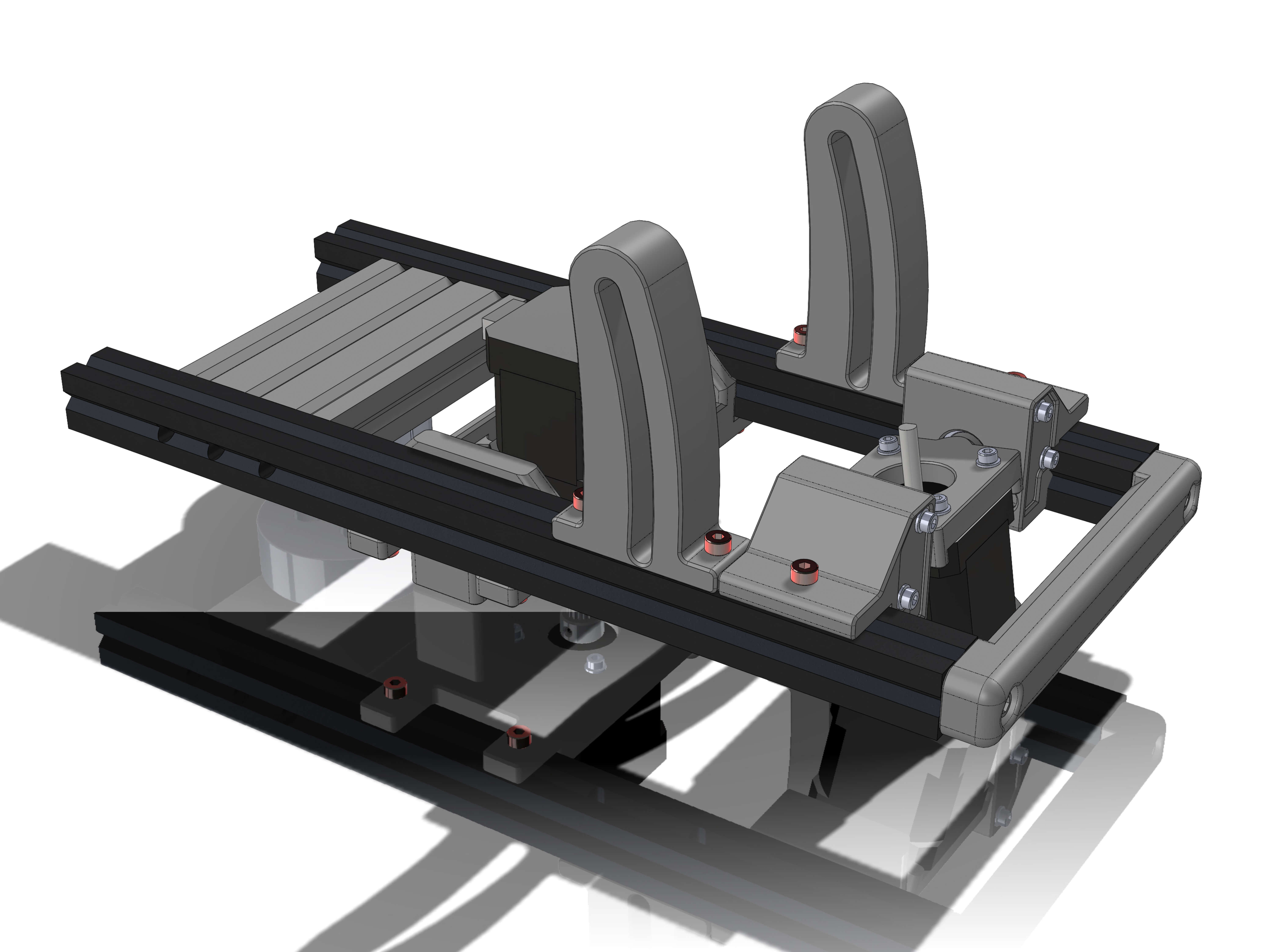
Hardware:
- 2x 300mm (EX-B)
- 1x 2060x100 extrusion OR 3x 2020x100 (tapped EX-G) extrusion
- M5/M6x20 (6) buttonhead screws
Attach the 2060/2020x100's to the ALT-AZ extrusions as shown, making sure you can see the buttonheads through the holes. Tighten the screws to torque 5.
Do this on a flat surface to ensure all extrusions are parallel to each other.
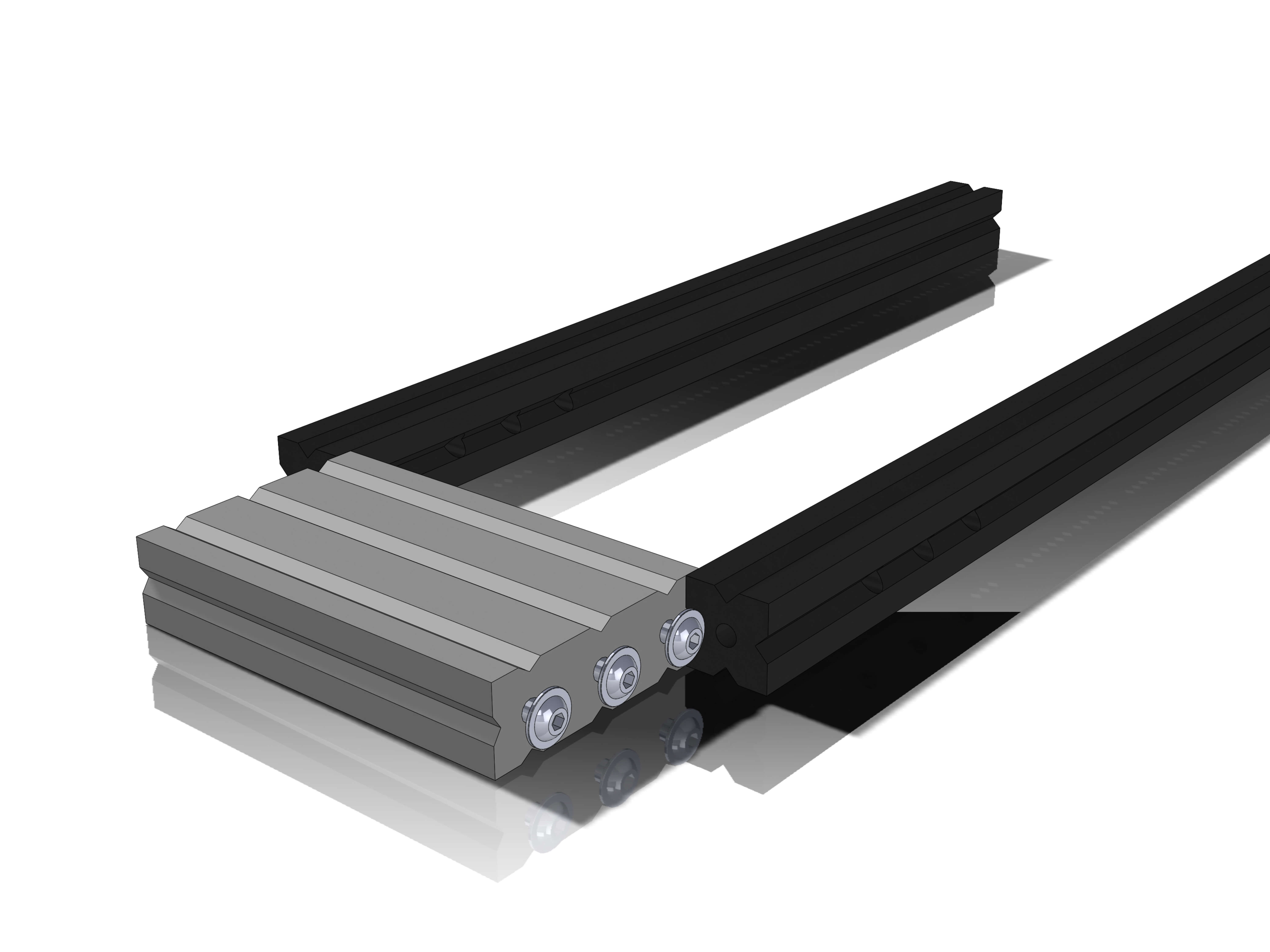
This section is for EQ tripods only, skip for different tripods
Parts:
- Tripod_adapter_EQ5_1
- Tripod_adapter_EQ5_2
Hardware:
- M5x12 screws (4)
- M6 washers (4)
- M5 T-nuts (4)
- M4x12 screws (2)
- M4 inserts (2)
Insert the M4 inserts as shown into the half without the through holes.
Attach the four M5x12, M5 T-nuts and M6 washers through the two adapter halves as shown.
Then screw the two halves together with two M4x12 screws.
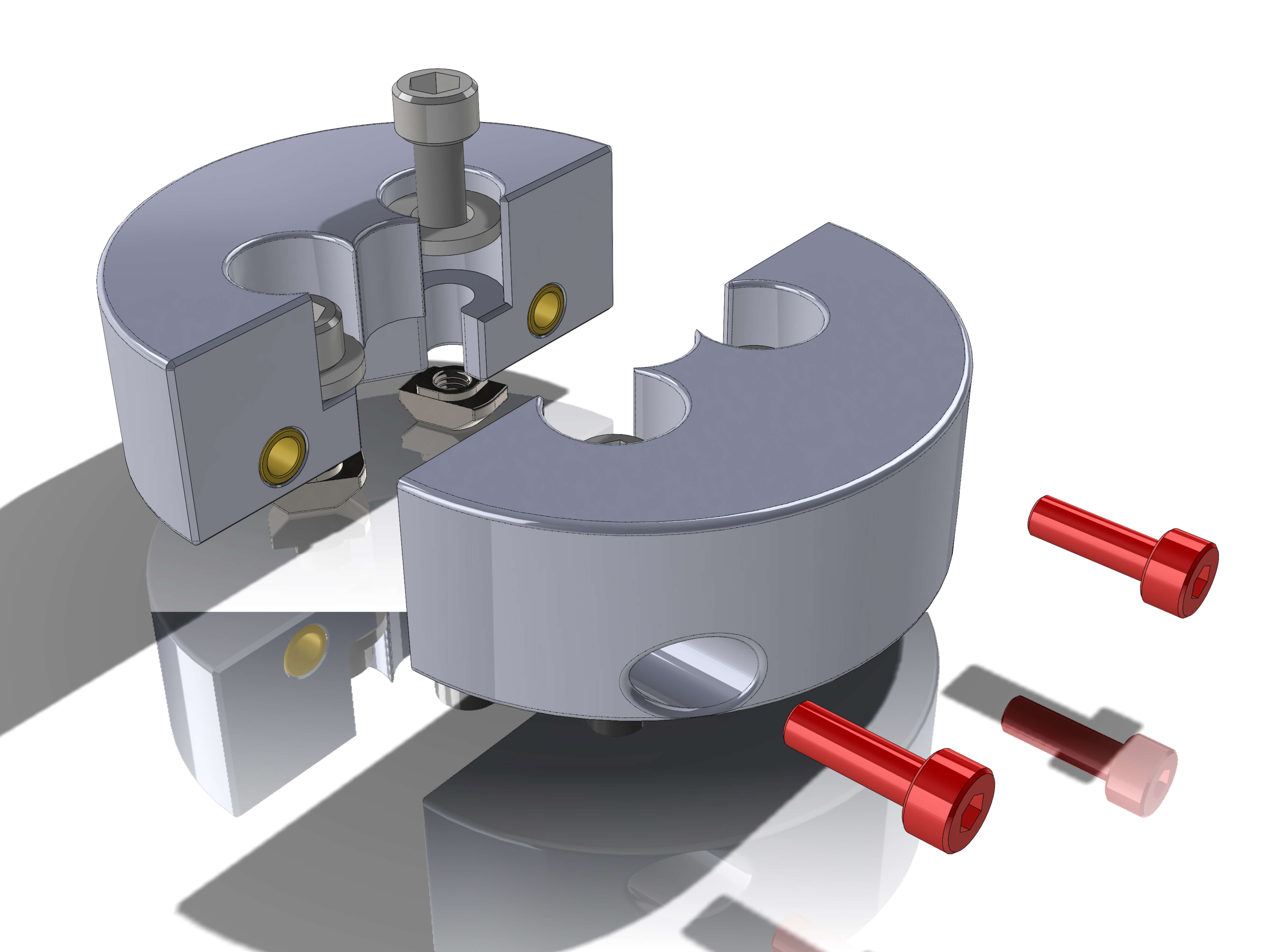
Parts:
- AZ_motor_mount
Hardware:
- NEMA17
- M3x10 screws (4)
- M3 washers (4)
- M3 inserts (4)
Insert the M3 inserts as shown (in yellow). Attach the NEMA with the four M3x10 screws as shown. The cables of the stepper should face the side that has inserts.
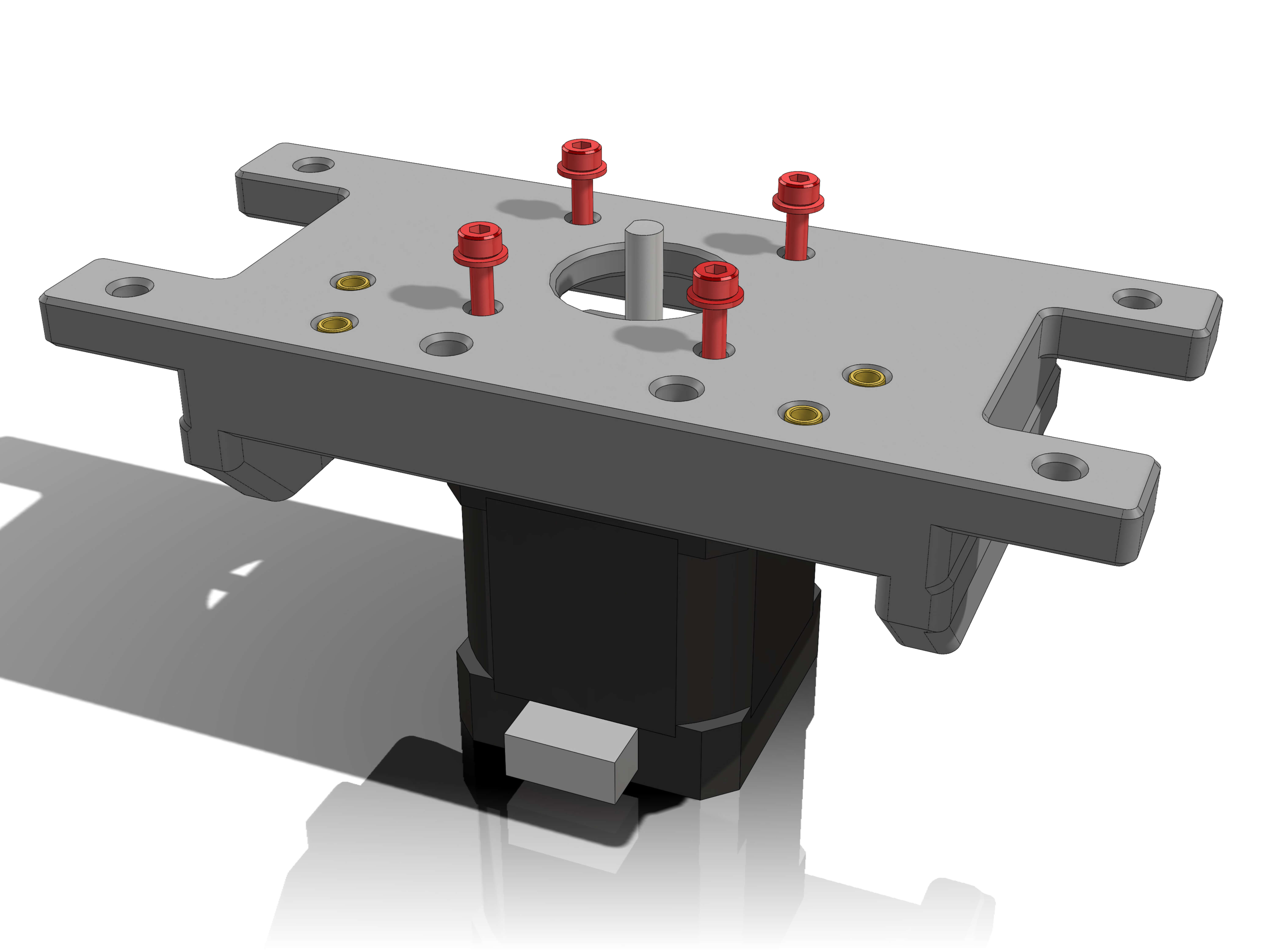
Parts:
- AZ_idler_mount
Hardware:
- M3x12 screws (4)
Attach the idler mount as shown. Don't fasten the screws yet.
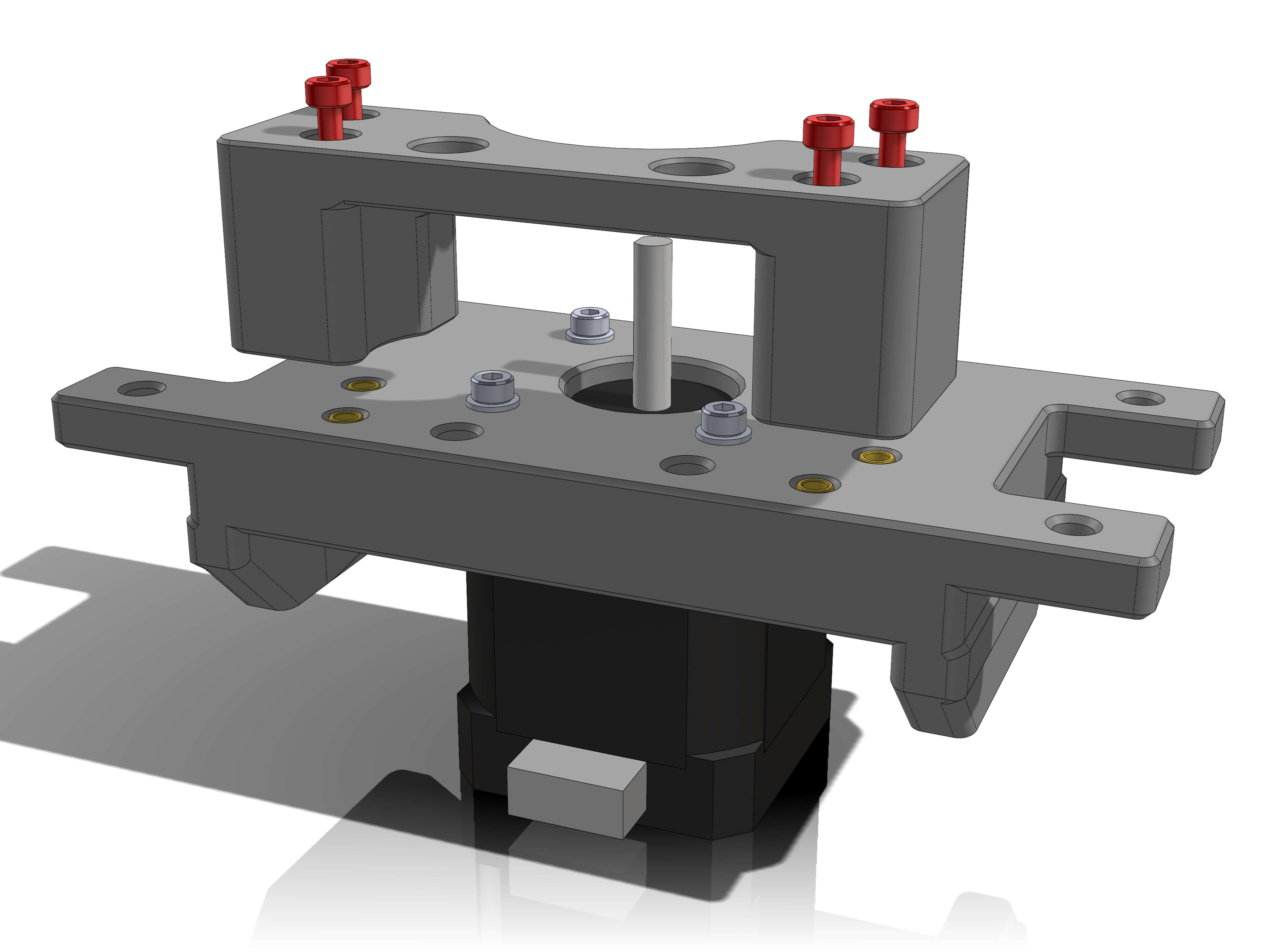
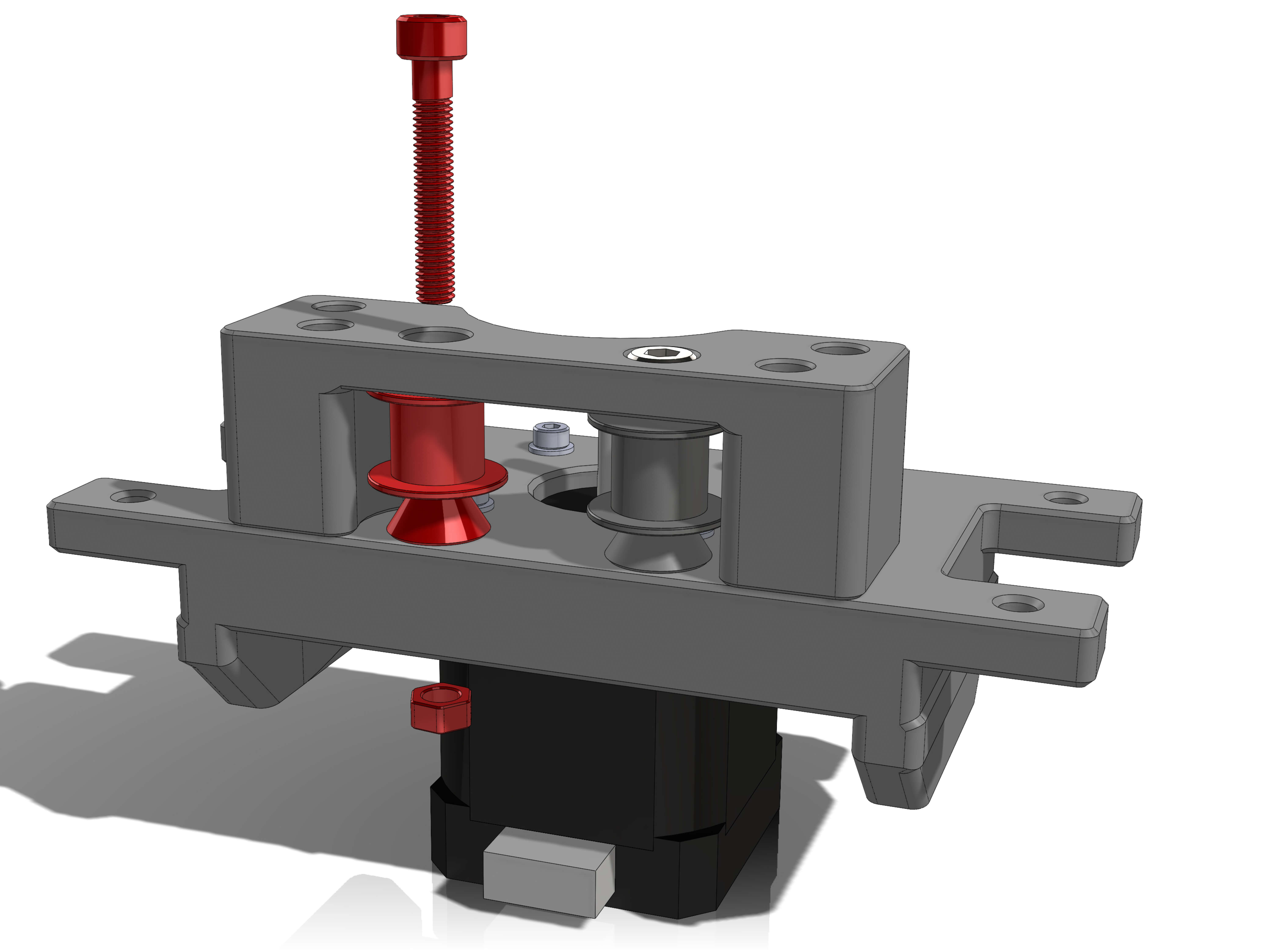
Parts:
- AZ_idler_distancer
Hardware:
- M5x30 screws (2)
- M5 nuts (2)
- 2GT idlers (2)
- 2GT 16T 9mm pulley
Attach the idlers as shown.
Atach the 9mm pulley to the stepper shaft, so that it lines up with the idlers.
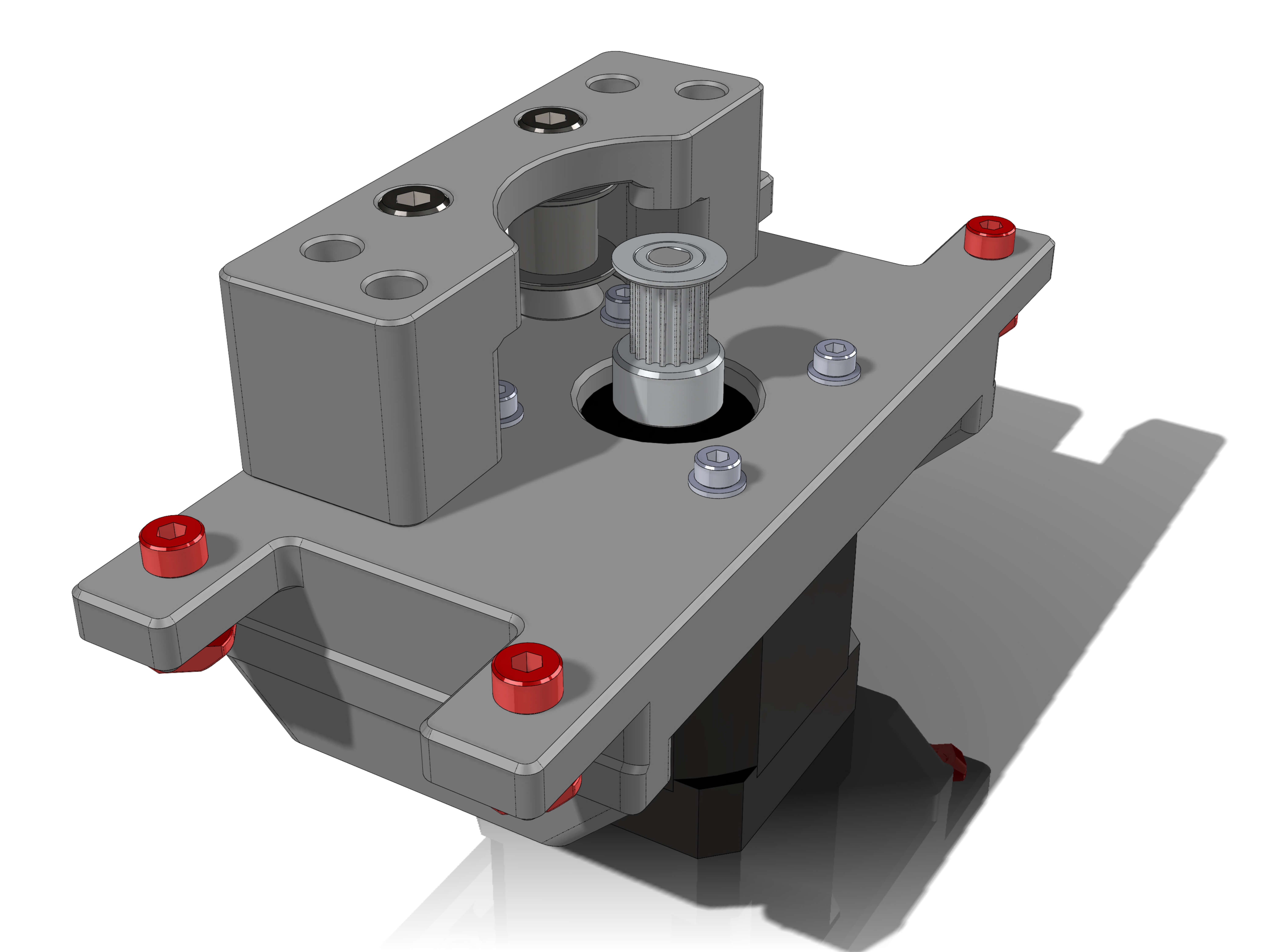
Hardware:
- M4x12 screws (4)
- M4 T-nuts (4)
Attach the four M4x12 and T-nuts in the shown locations. Note the orientation.
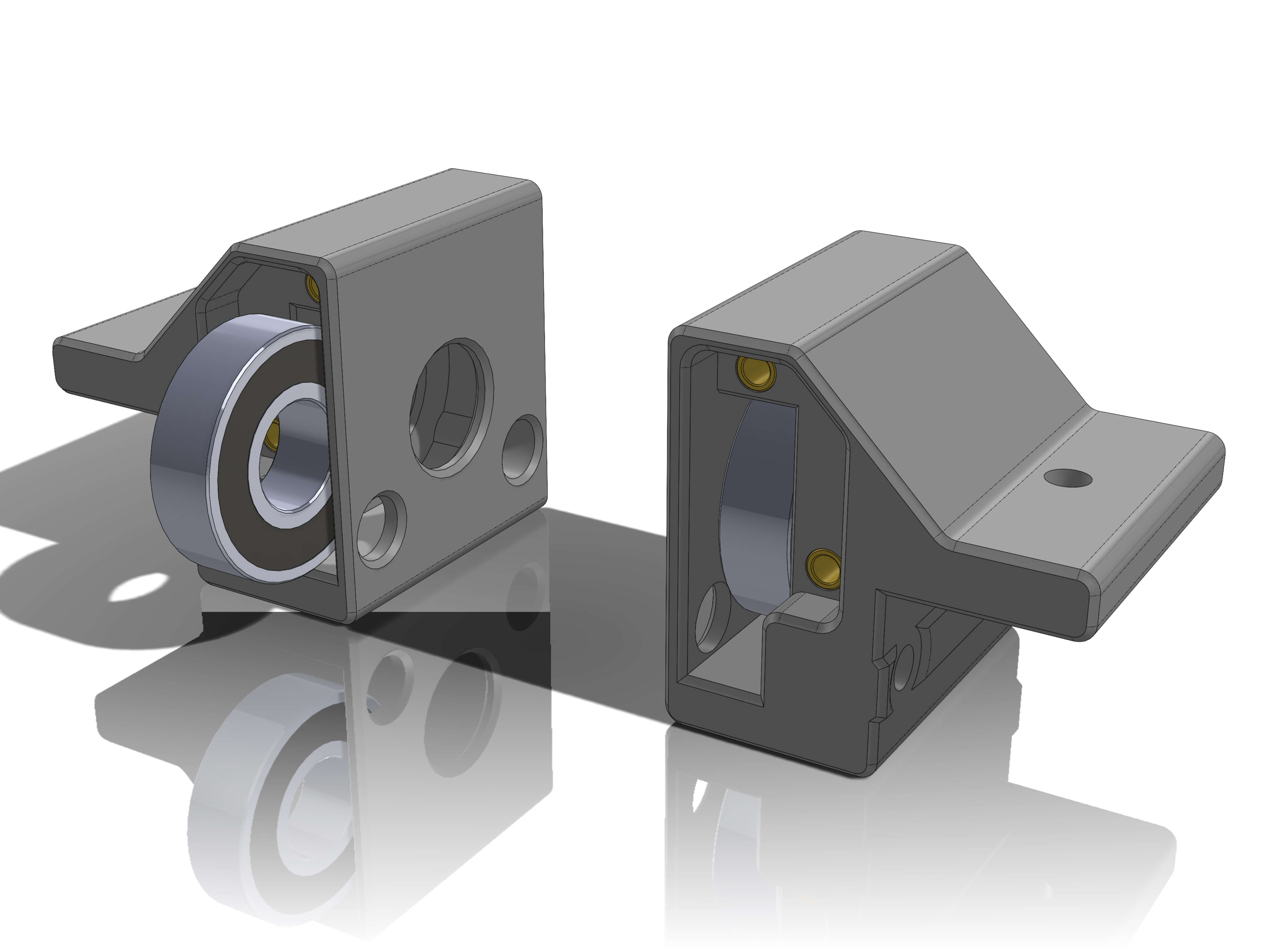
Parts:
- ALT_holder_left
- ALT_holder_right
Hardware:
- 6001 bearings (2)
- M3 inserts (4)
Insert two M3 inserts in each holder in the shown holes.
Insert the two 6001 bearings into the ALT_holders.
Parts:
- ALT_bearing_lid_left
- ALT_bearing_lid_right
Hardware:
M3x12 screws (4)
M3 washers (4)
Attach the bearing lids as shown.
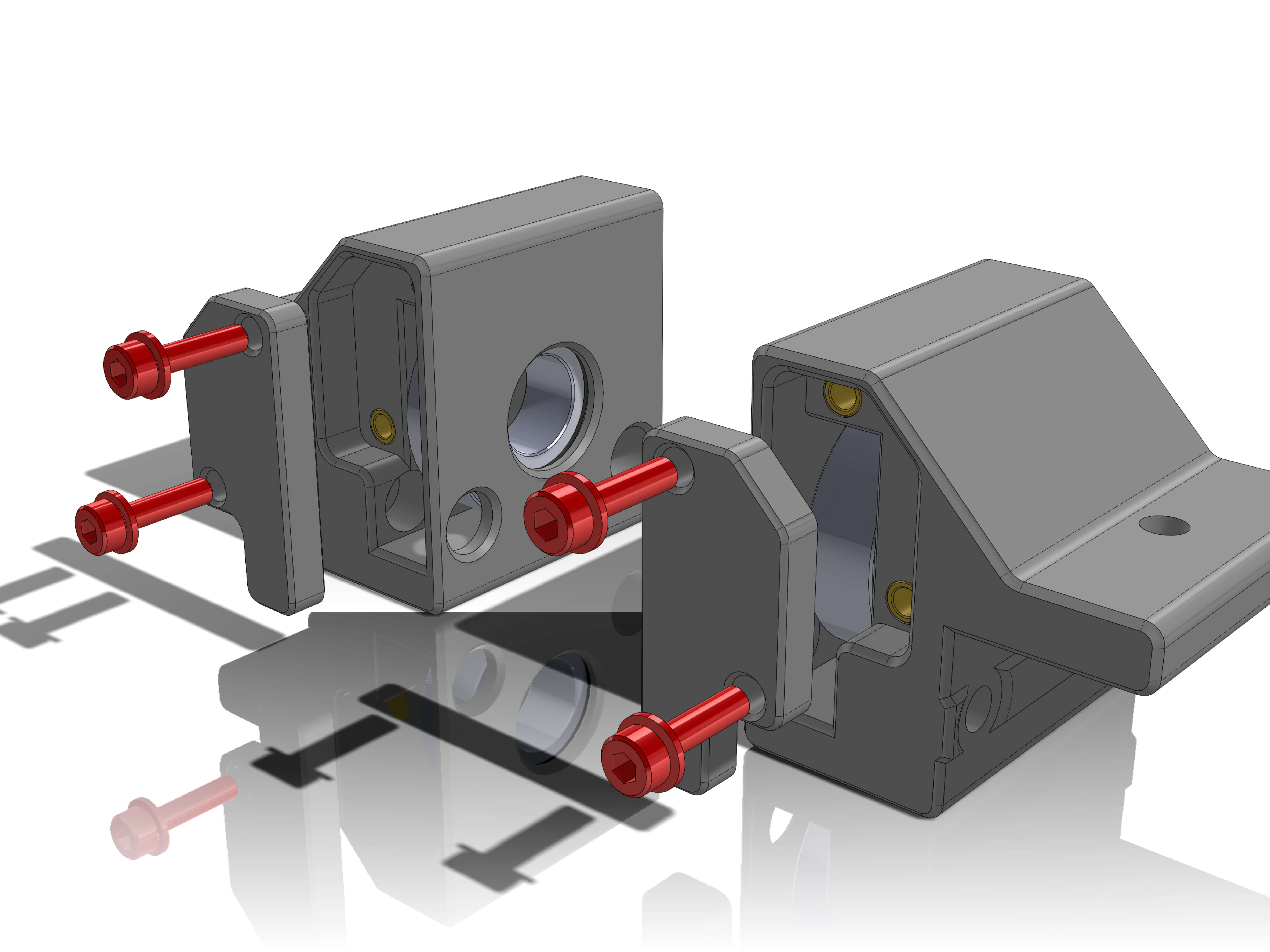
Parts:
- ALT_motor_holder
Push the ALT_motor_holder into the bearings in the ALT_holders. Make sure the connection doesn't have too much play.
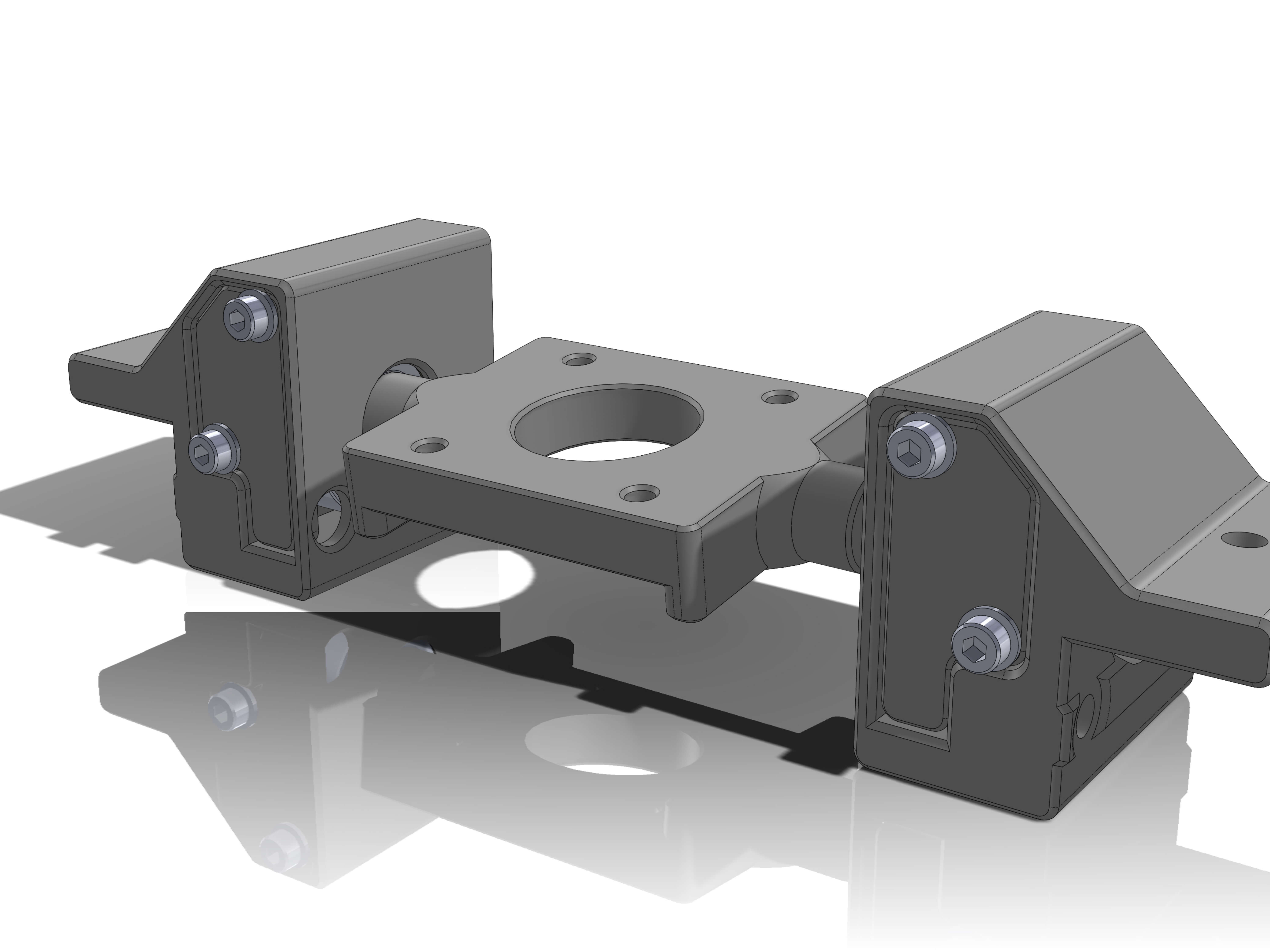
Hardware:
- NEMA17
- M3x12 screws (4)
- M3 washers (4)
- M4x12 screws (2)
- M4 T-nuts (2)
Attach the NEMA17 with the M3x10 screws and washers.
Attach the M4x12 screws and T-nuts on the shown locations.
If you are above 45° Latitude, make the stepper cable face away from the bearing_lids.
If you are below 45° Latitude, make the stepper cable face the bearing_lids.
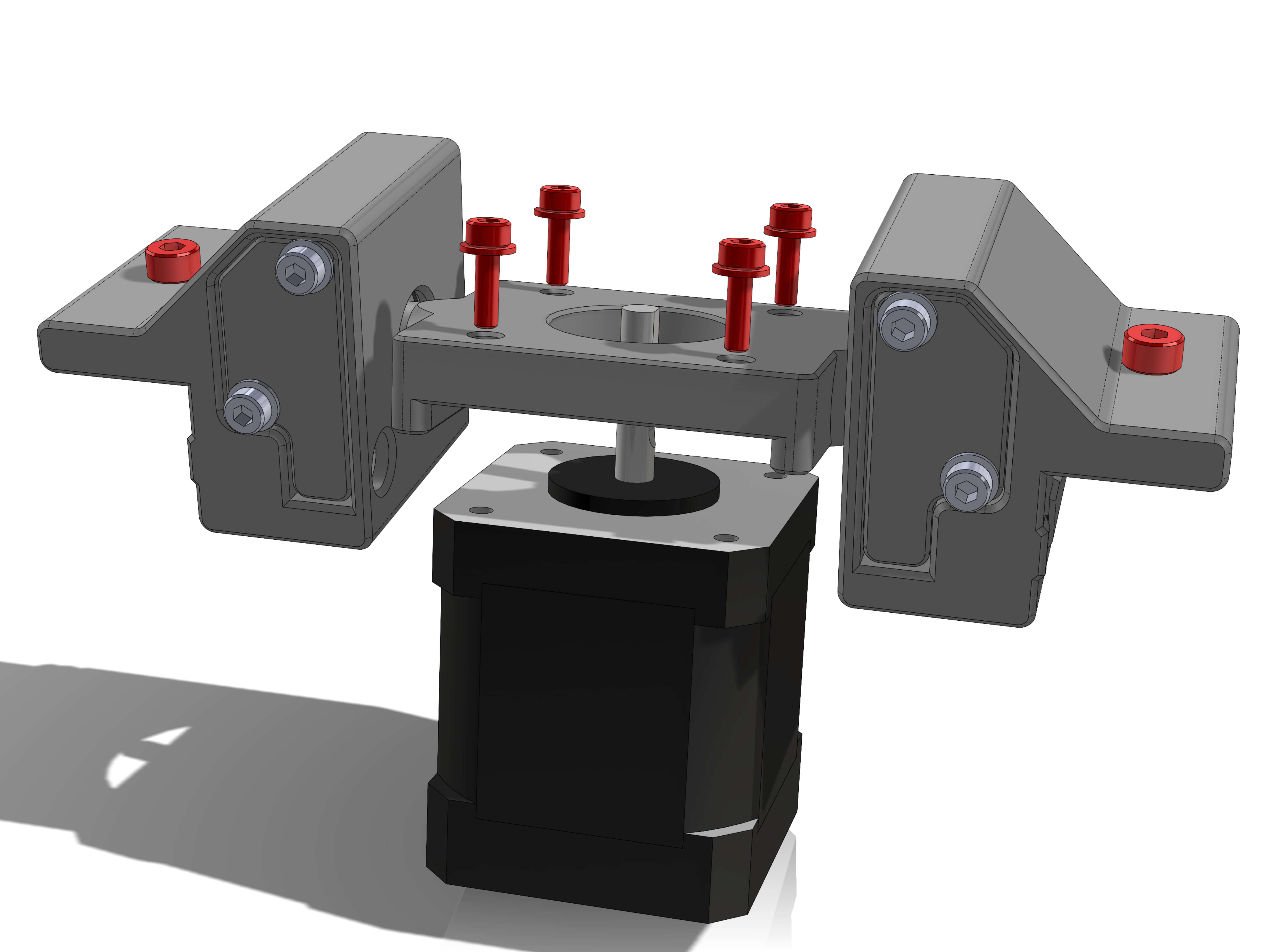
Hardware:
- ALT-AZ alu extrusions
- EQ5_tripod adapter
- M10 nut
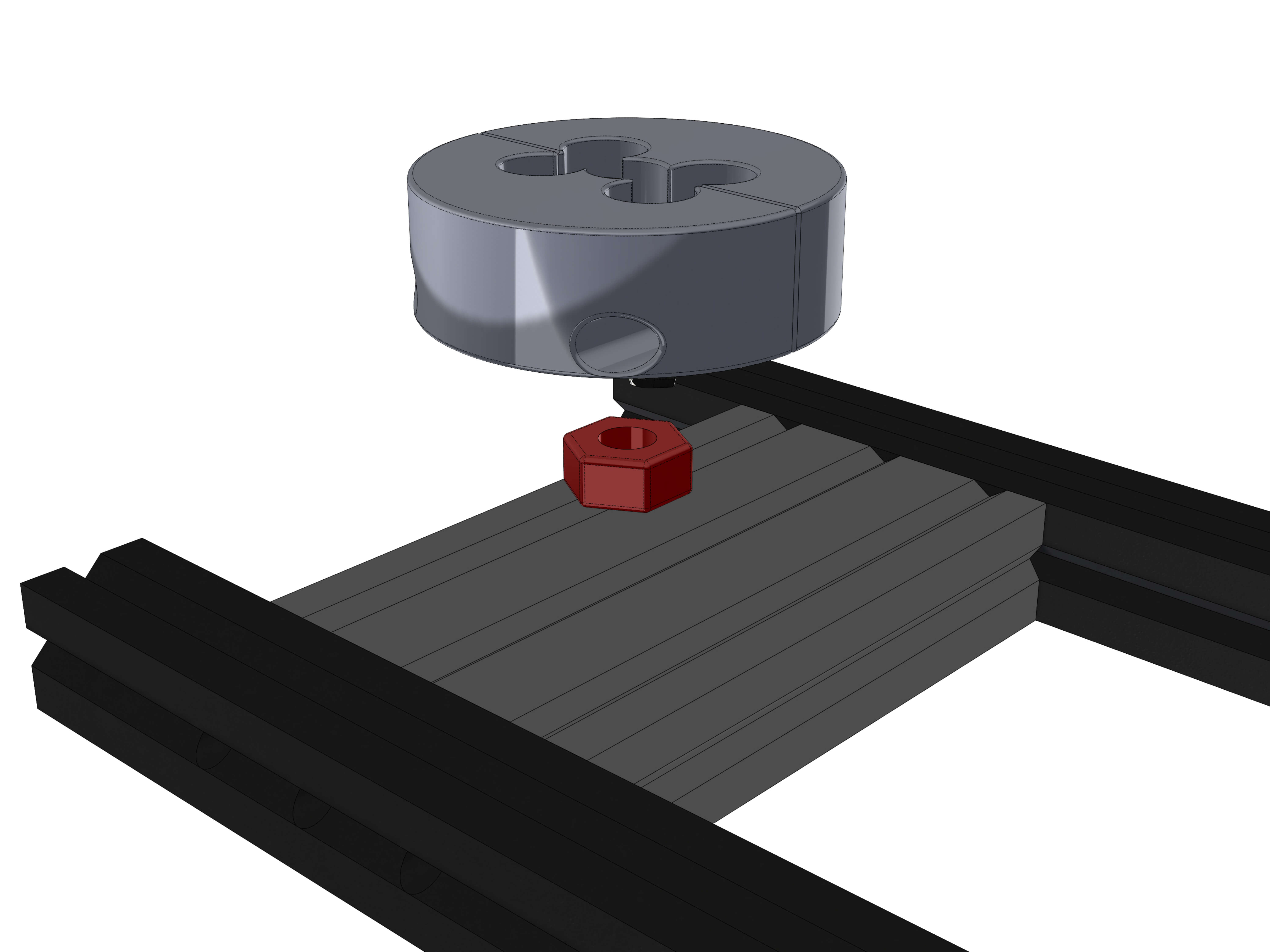
Take the extrusions and the adapter from earlier.
Insert the M10 nut into the EQ5_adapter, then use the M4 screws to mount the adapter to the alu extrusion. Make sure it's more or less centered.
Now attach the AZ_stepper assembly as shown. Tighten it only slightly for now so it doesn't move. The exact position will determined later. The pulley should be on the same side as the tripod adapter. The idlers and the steppers cable should face the front (Tripod adapter).
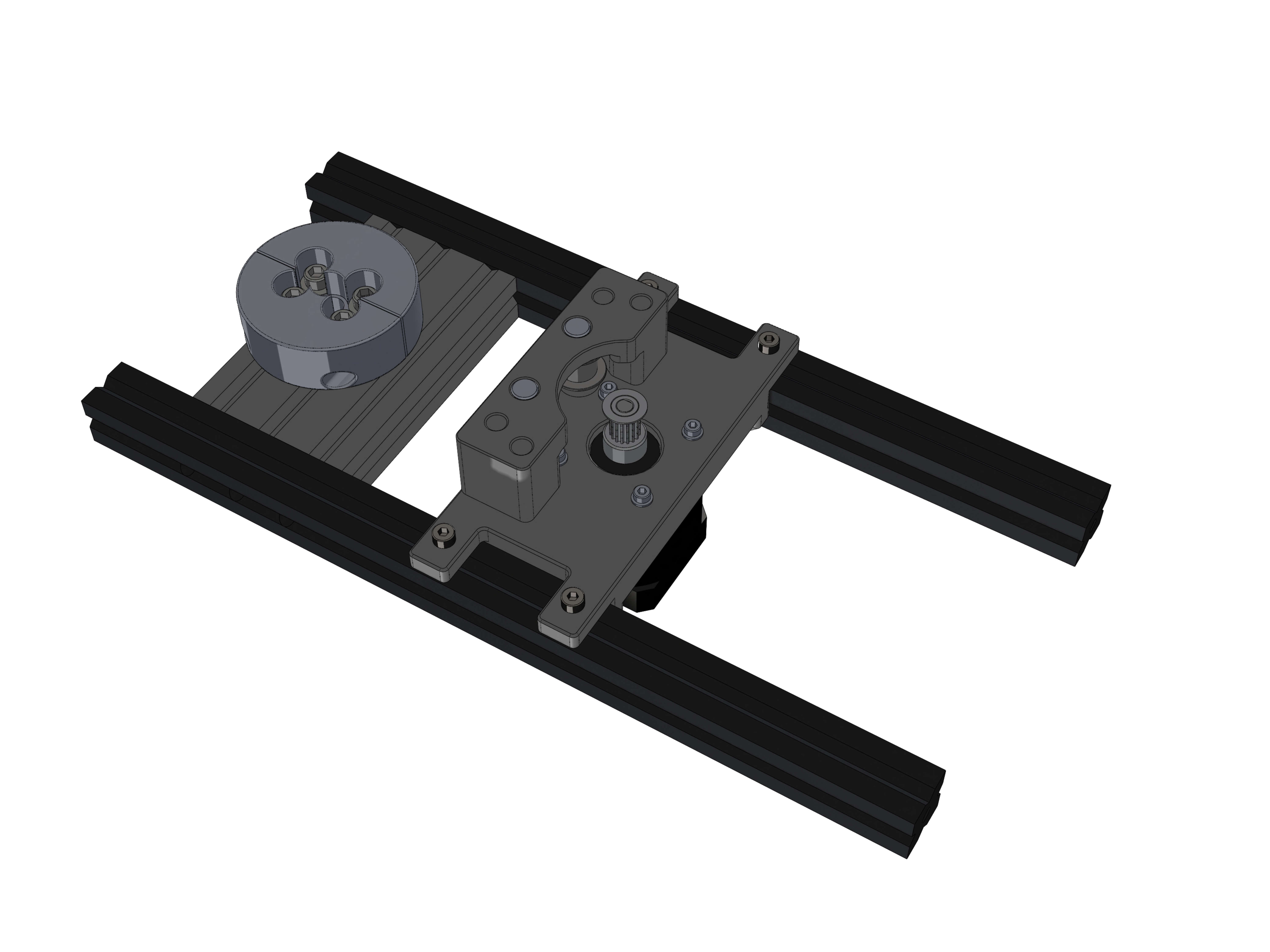
¶ ALT assembly for 0-45° Latitude
If you are above 45° Latitude, skip to here
Hardware:
- 2020x200mm (2) tapped on one end
- M5/M6x20 buttonhead screws (2)
Depending on where you are located, screw the two extrusions to the correct hole and tighten the screws to torque 5.
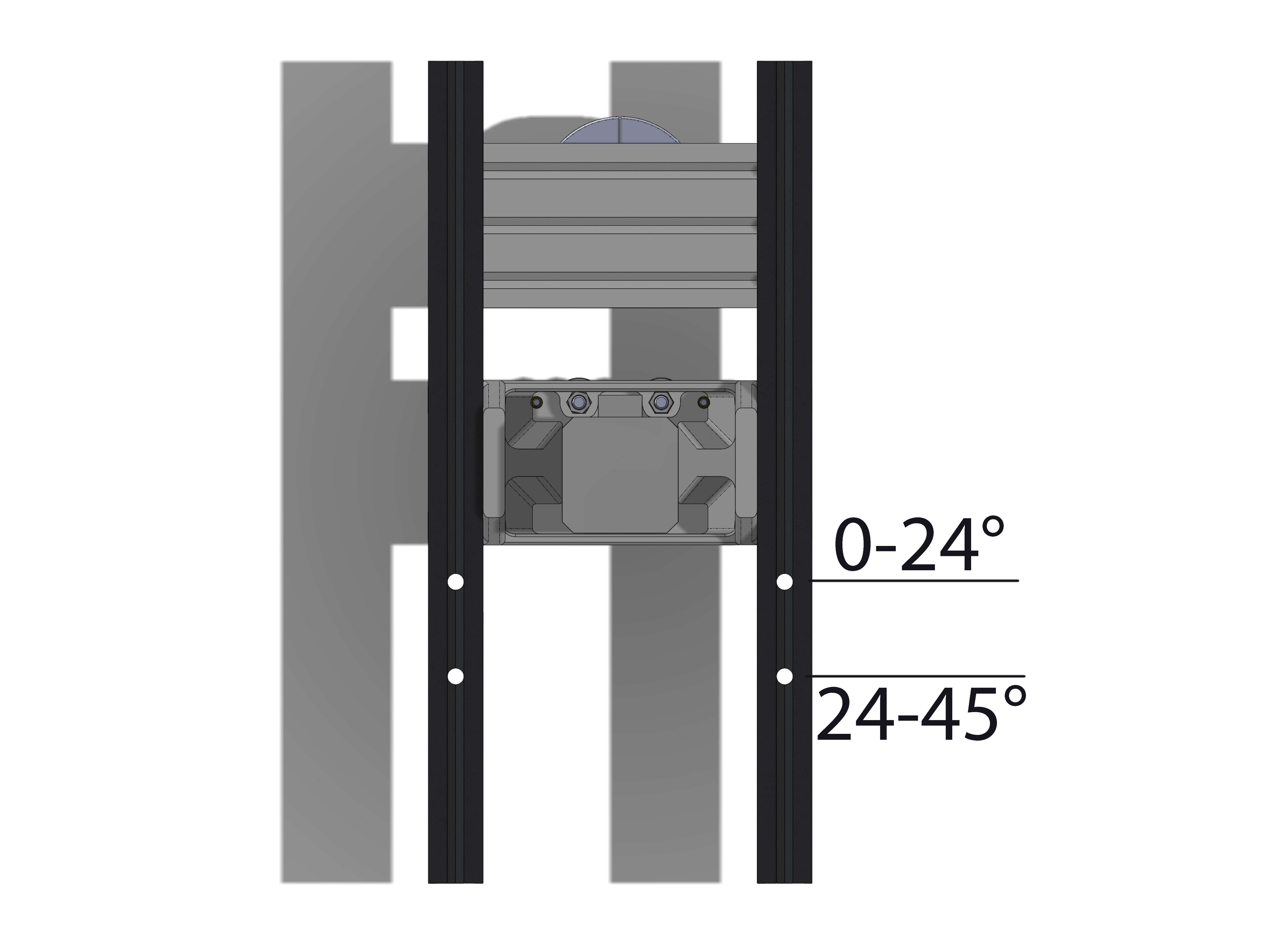
Take the ALT stepper assembly and slide it onto the extrusions from the top. Tighten the screws lightly, the exact position of the stepper will be adjusted later.
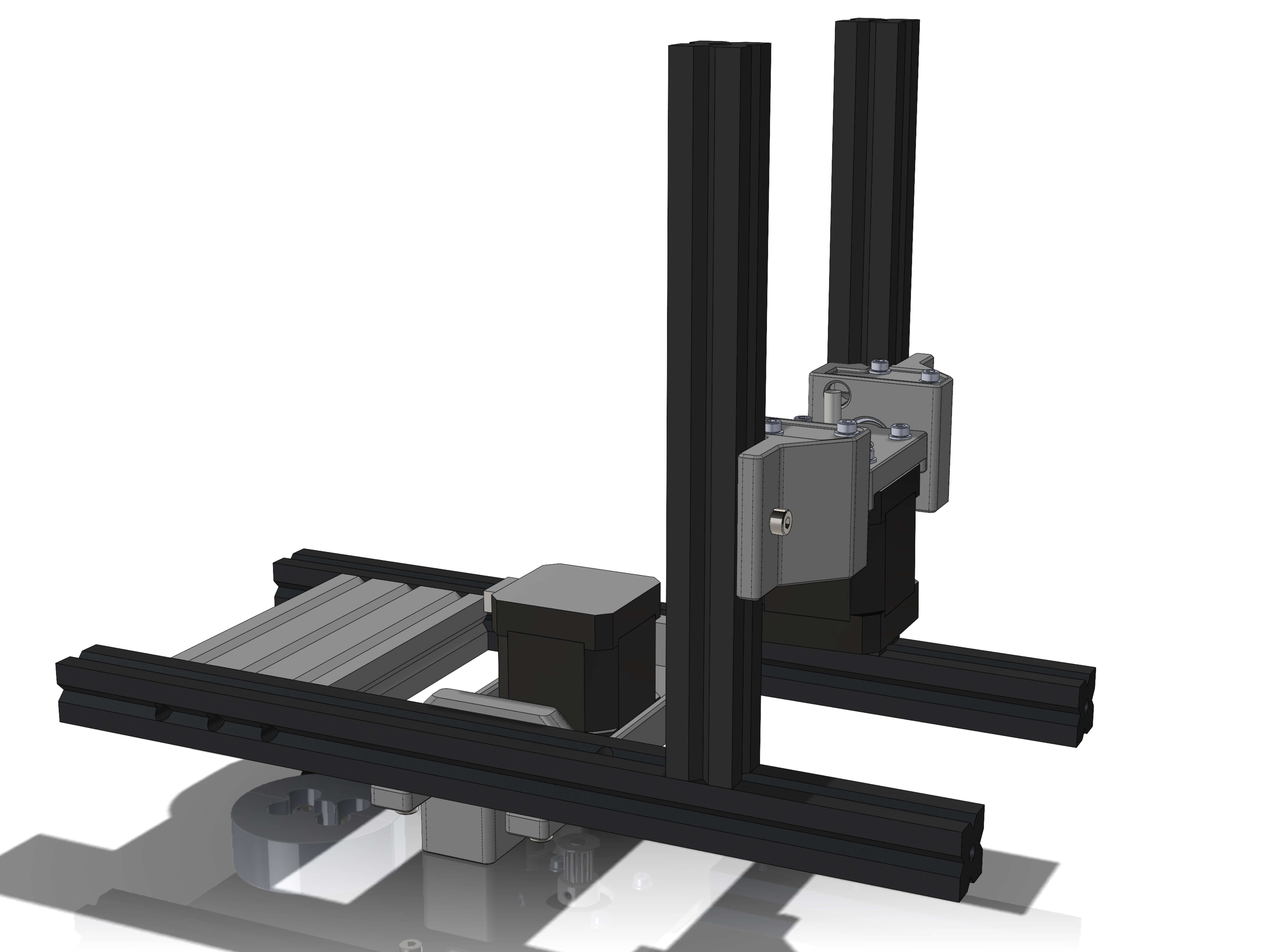
Parts:
- ALT_fastener_left_0-45deg
- ALT_fastener_right_0-45deg
Hardware:
- M4x12 screws (6)
- M4 T-nuts (6)
Attach the two ALT_fasteners as shown. If you don't know which part goes left and right, make the print surface side face inward.
The bottom side should be distanced to the top of the base extrusions by roughtly 50mm, however this will be spaced precisely in a later step.
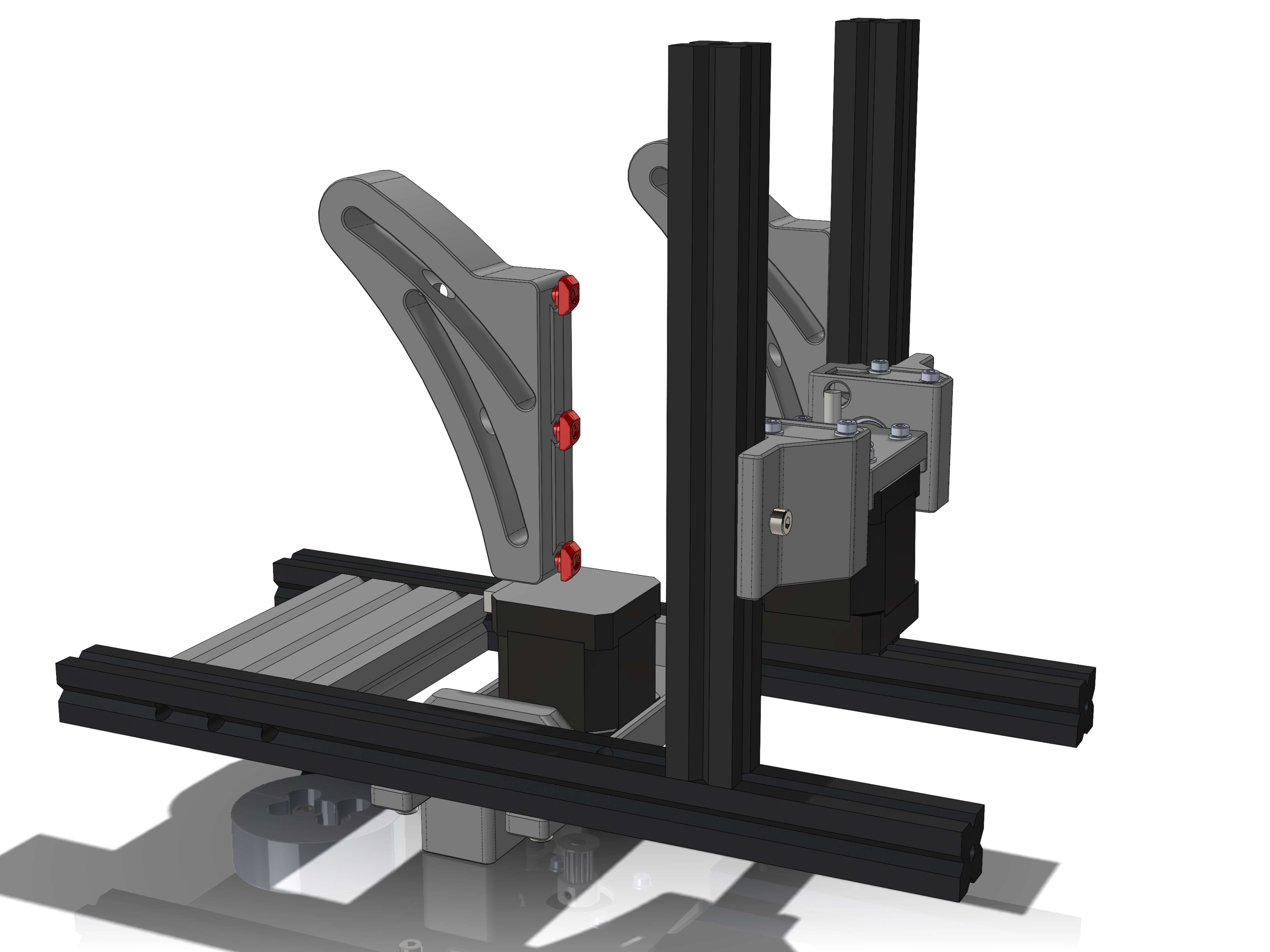
¶ ALT assembly for 45-65° Latitude
If you are below 45° Latitude, skip to here
Parts:
- ALT_fastener_left
- ALT_fastener_right
Hardware:
- M4x12 screws (4)
- M4 T-nuts (4)
Attach the ALT_fasteners with the M4 screws and T-nuts as shown. If you don't know which part goes left and right, make the print surface side face inward.
The rear part of the fastener should be spaced roughly 65mm away from the end of the alu extrusion, however this will be spaced precisely in a later step.
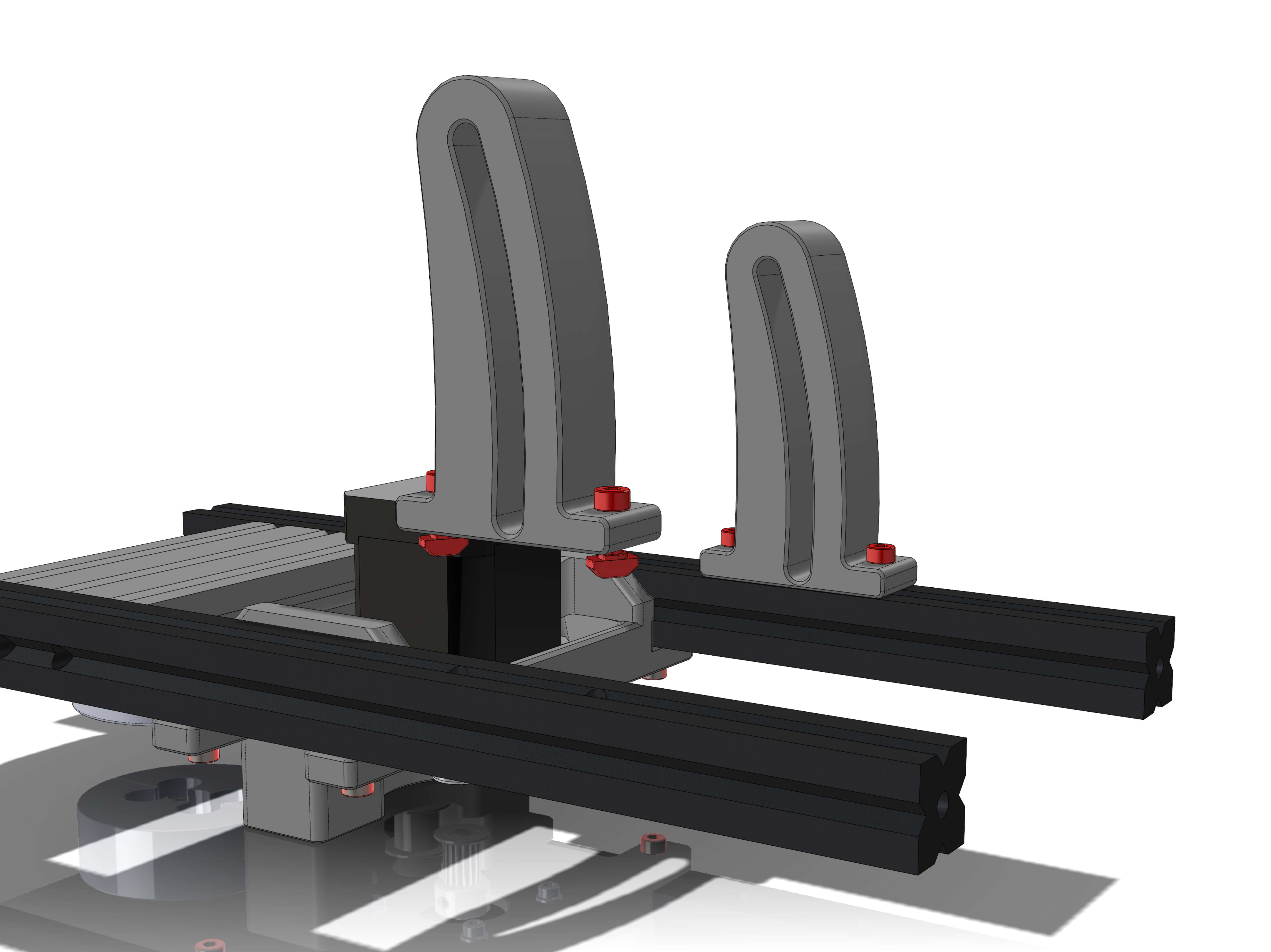
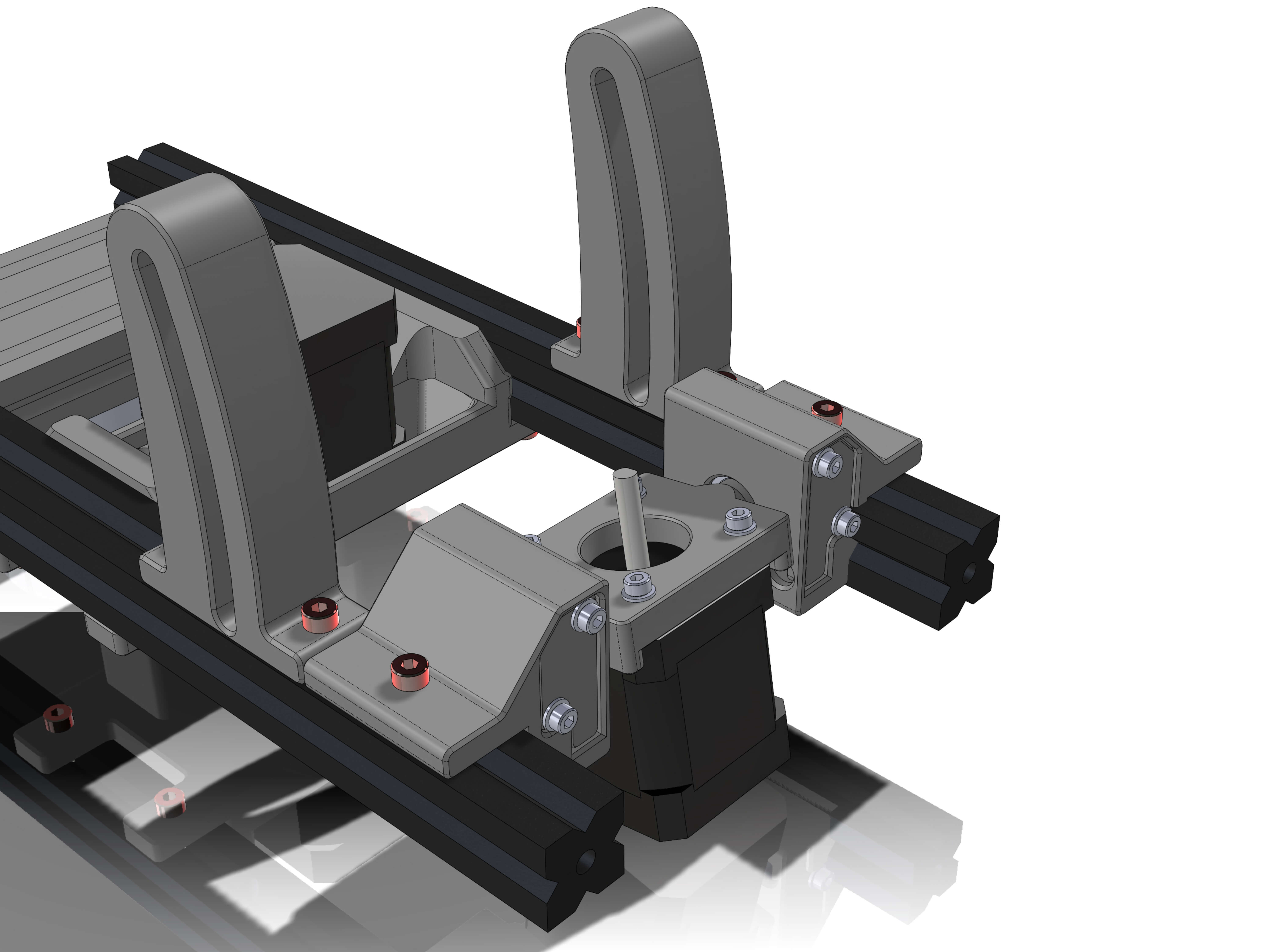
Slide the ALT stepper assembly onto the ALTAZ base extrusions as shown. Make the bearing_lids face the rear and the stepper cable the front.
¶ Rear Holder
Parts:
- rear_handle
Hardware:
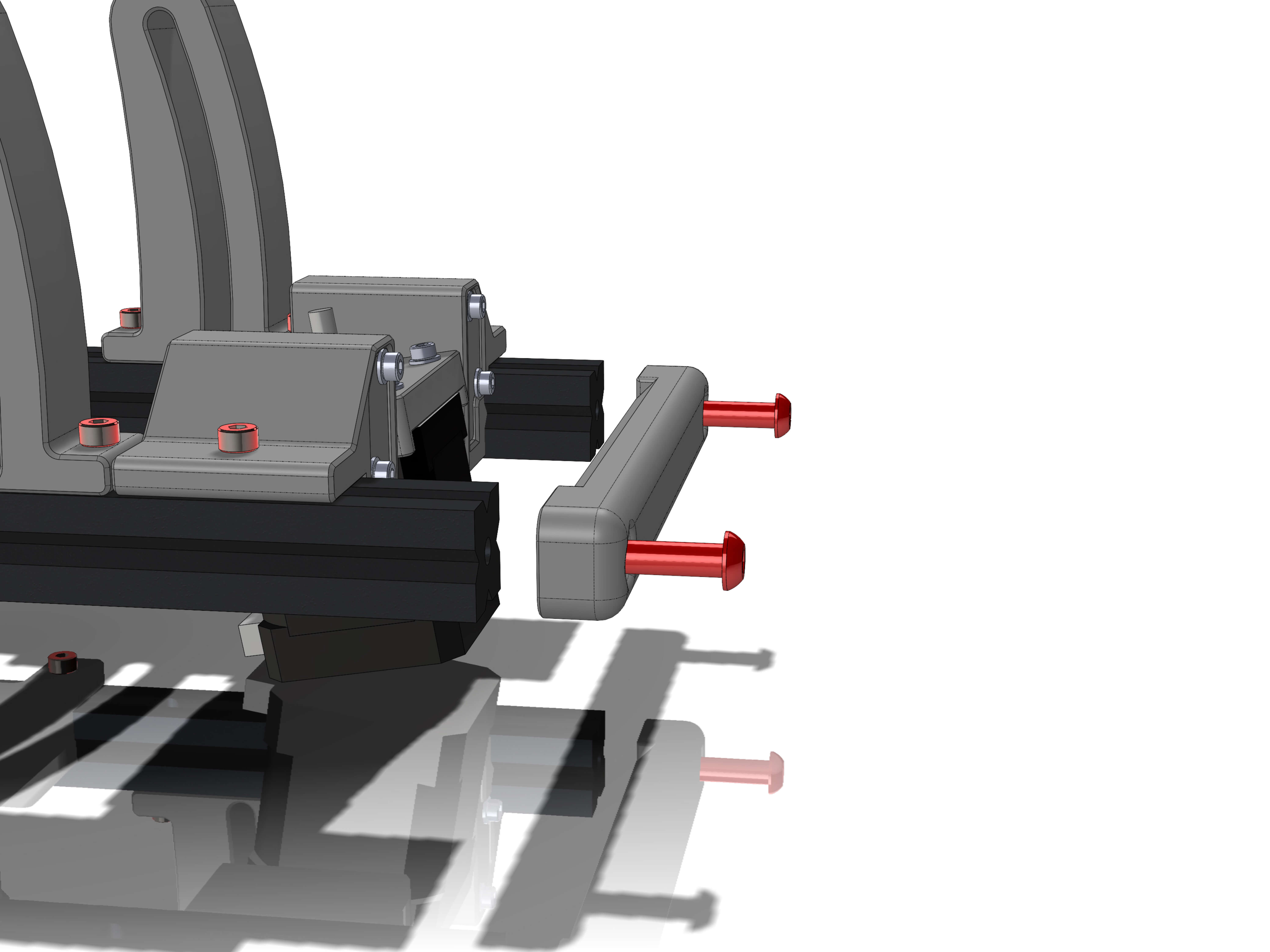
- M5/M6x20 buttonhead screws (2)
Lastly, attach the rear handle with two M5/M6 bolts.
Verify the connection is good and the print is fine. You will later carry the 12kg of the mount with this handle.
Congratulations, you have finished the ALT-AZ assembly of your OAM!

Continue with Part 3 of the instructions:
OAM Assembly Part 1: Base
OAM Assembly Part 2: ALTAZ base
OAM Assembly Part 3: Top Assembly
OAM Assembly Part 4: Gearboxes
OAM Assembly Part 5: Final Assembly