This is the page for the outdated version 3.0 of the OpenAstroGuider. See this page for version 3.1
¶ Preparations
¶ Inserts
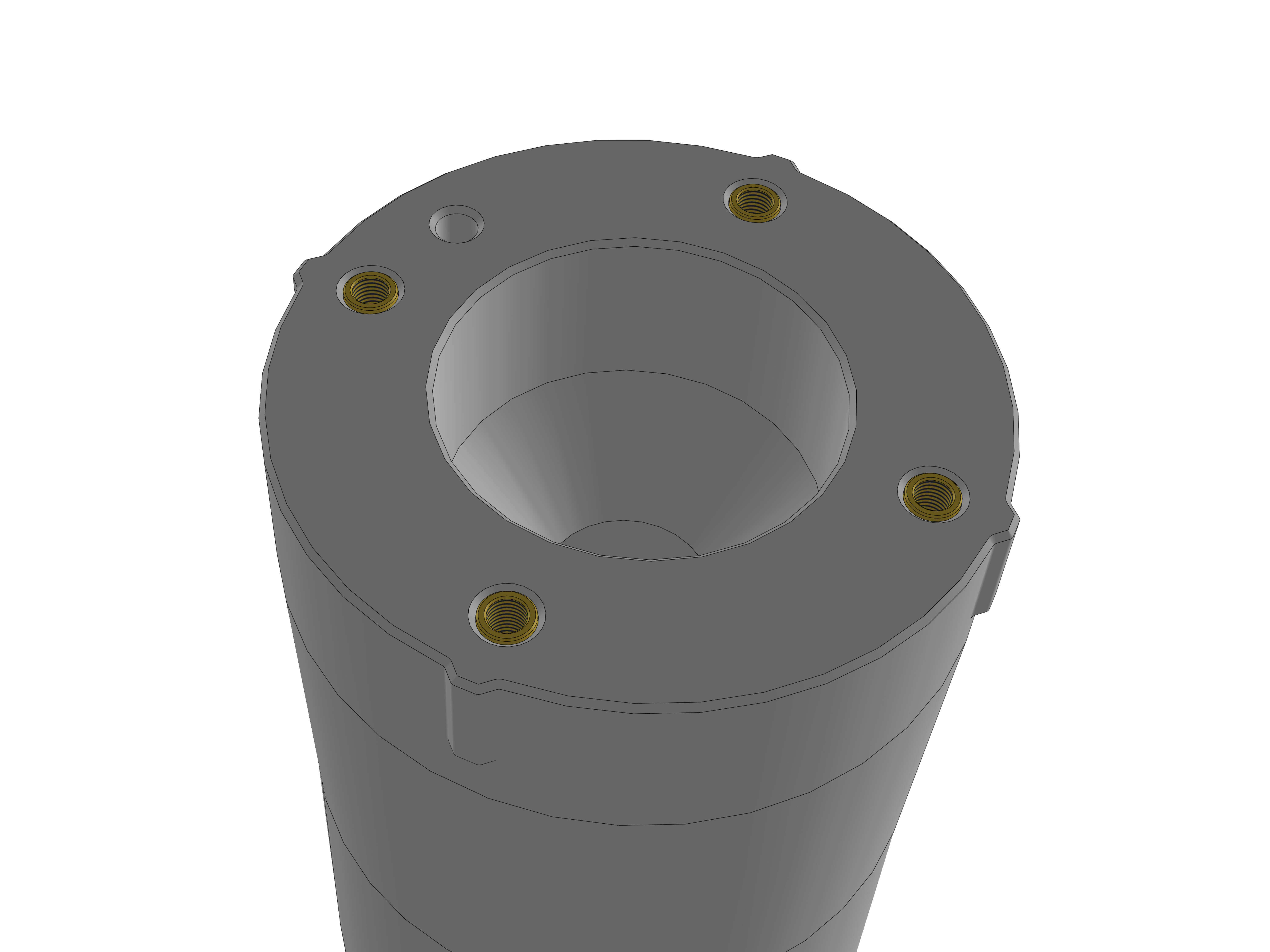
If you choose to build OAG v3 with inserts, you will need to use 4 M3x4.6x6 inserts for the rear part. Make sure theyre a little past flush and the surface stays smooth.
¶ Assembly
Unpack the lens and Dew heater.
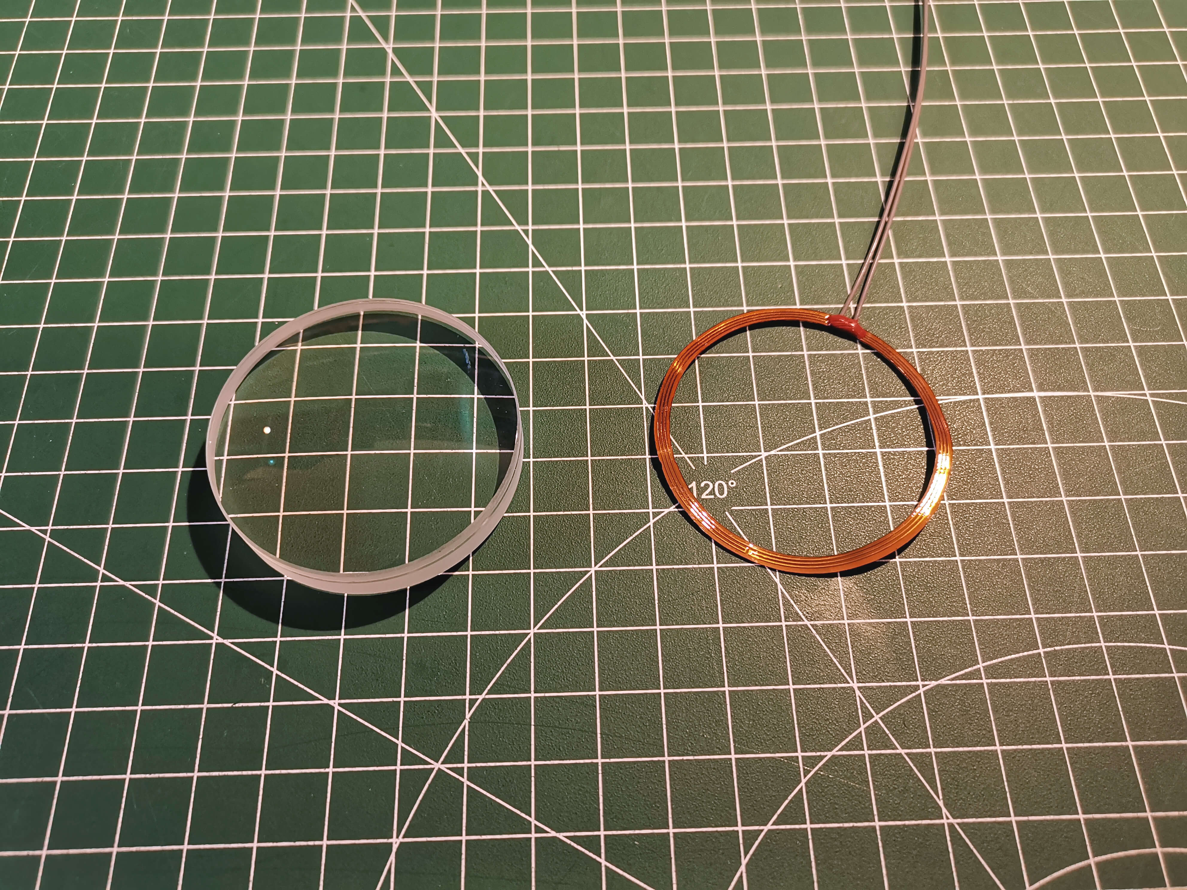
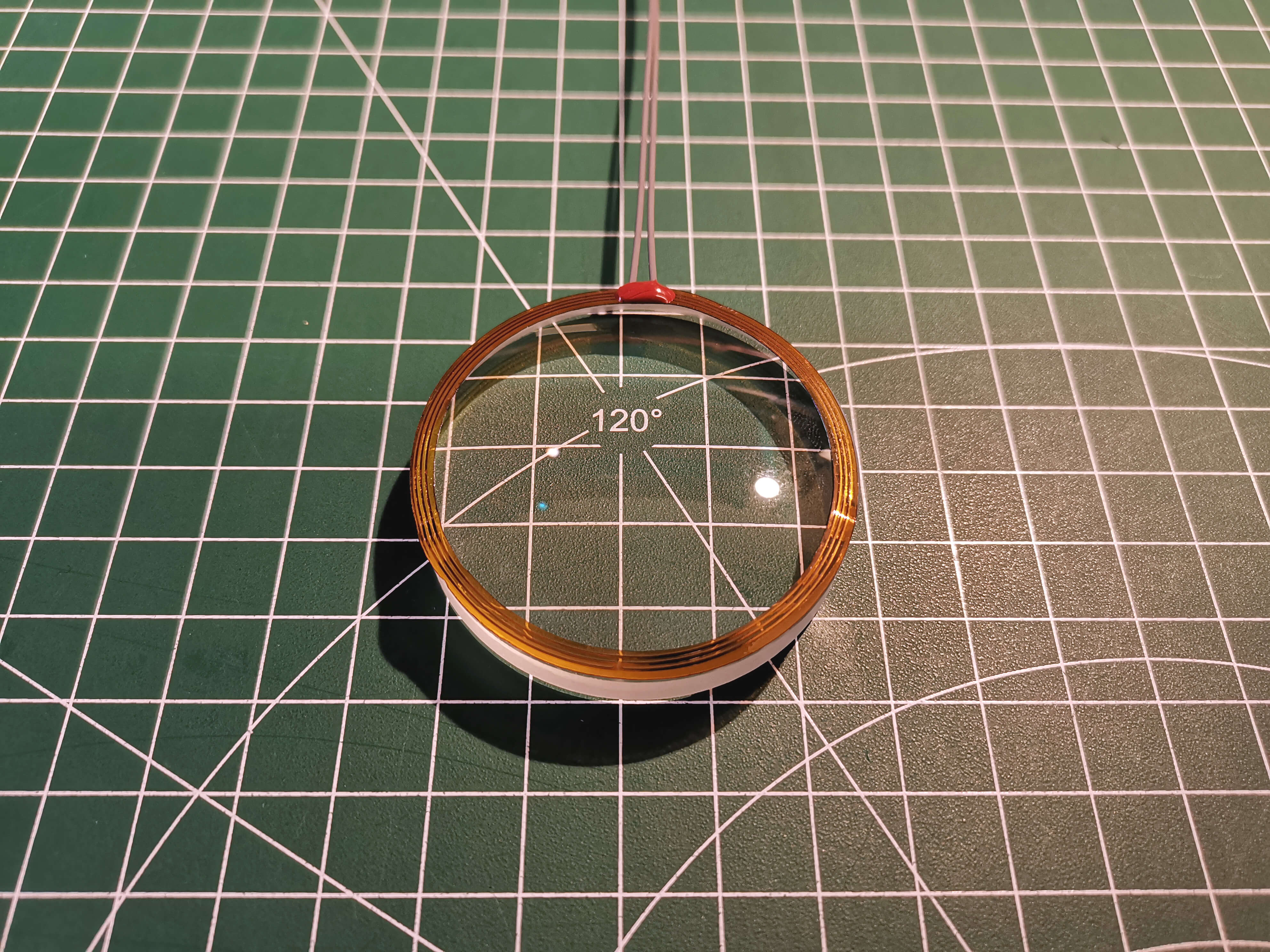
Carefully remove the cover from the gluestrip on the heater and place it on the top edge of the lens. The top is the part that has more curvature.
If you don't have any grease available, skip this step. Adding some grease is recommended though.
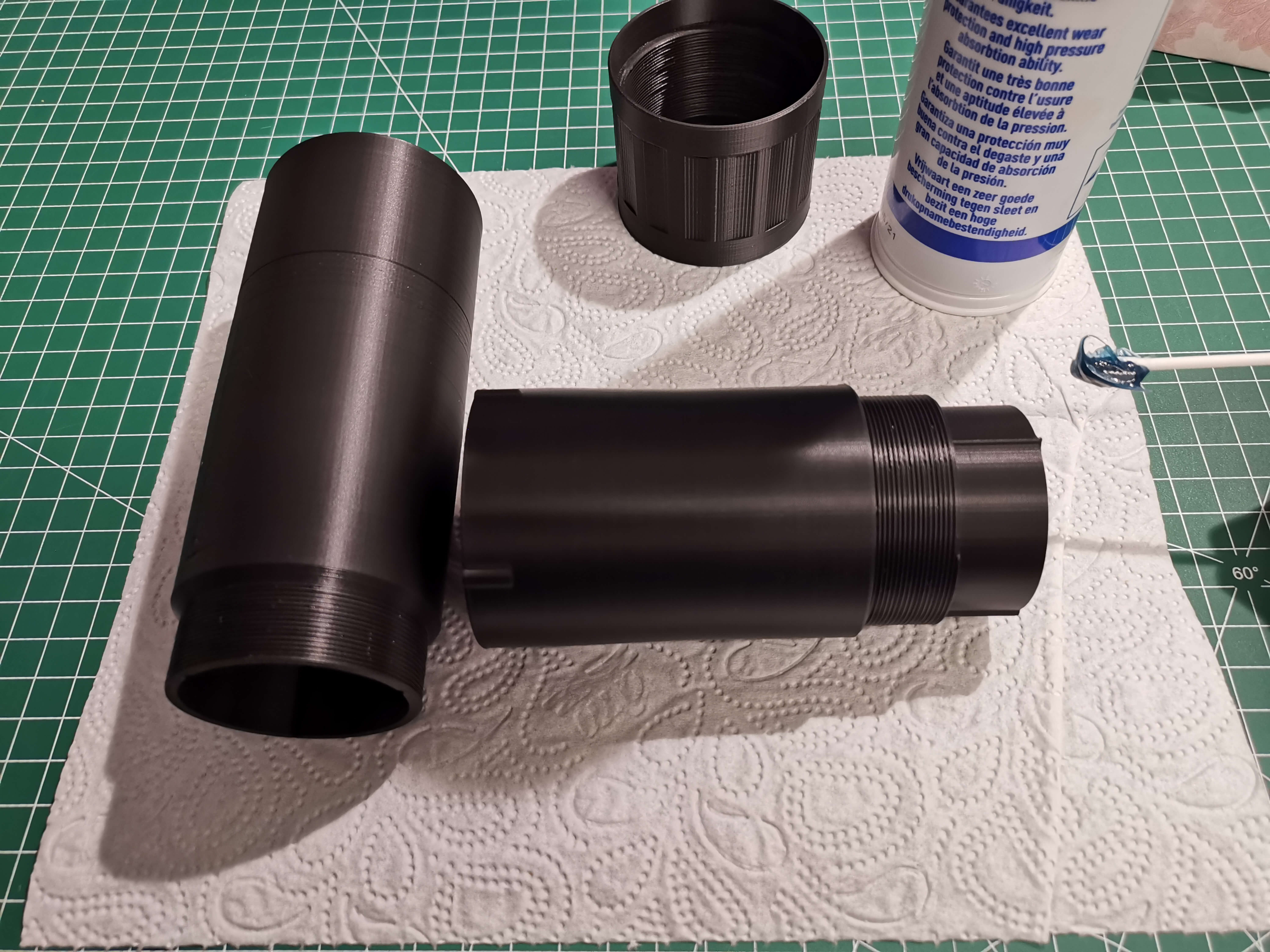
Apply a generous amount of general purpose grease to the thread and top section of the rear part. Apply extra grease to the three sprockets.
Also apply grease to the thread part of the front guider part.
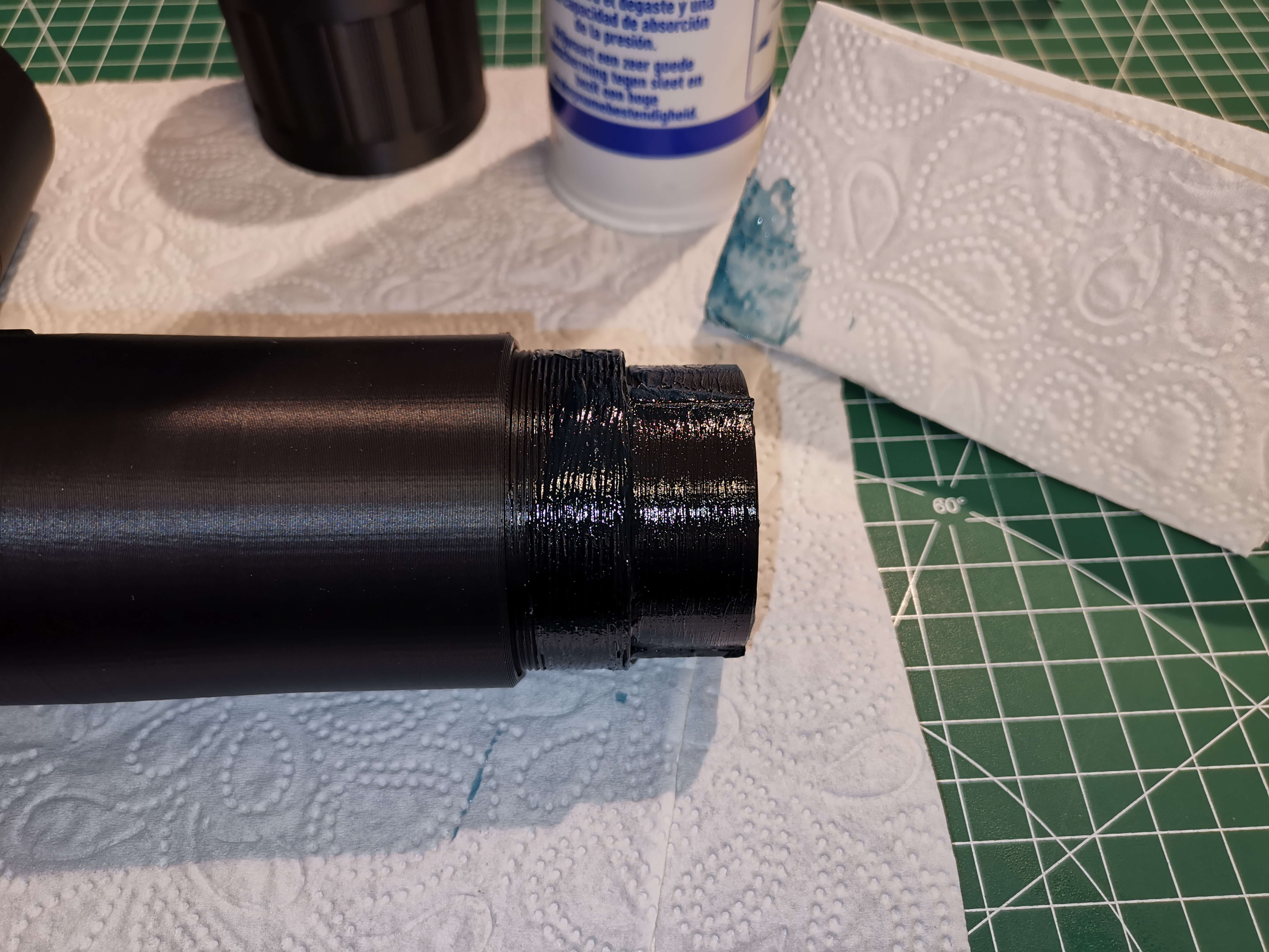
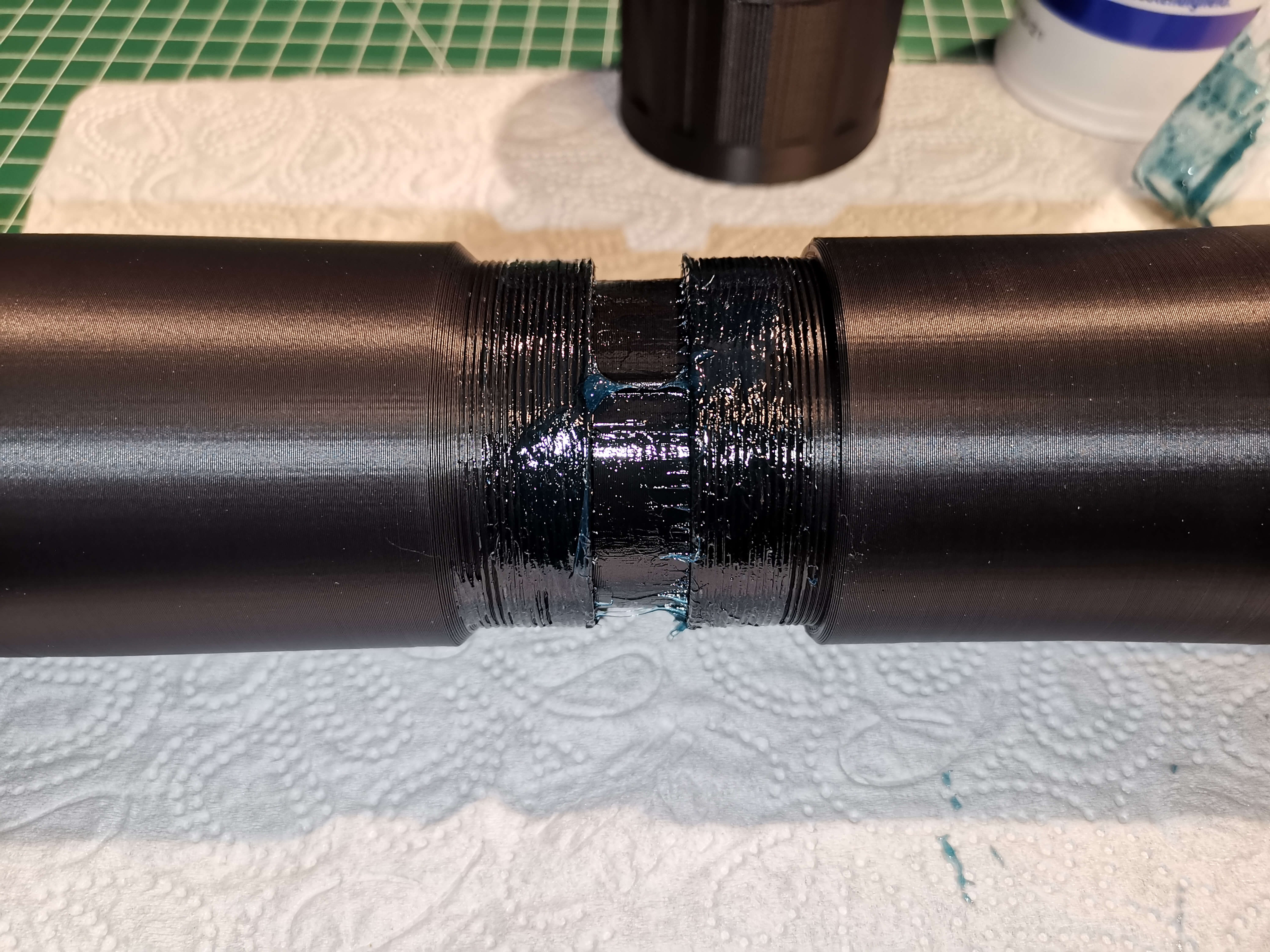
Put the two pieces together without the mid part and move them in and out a few times until they move smooth.
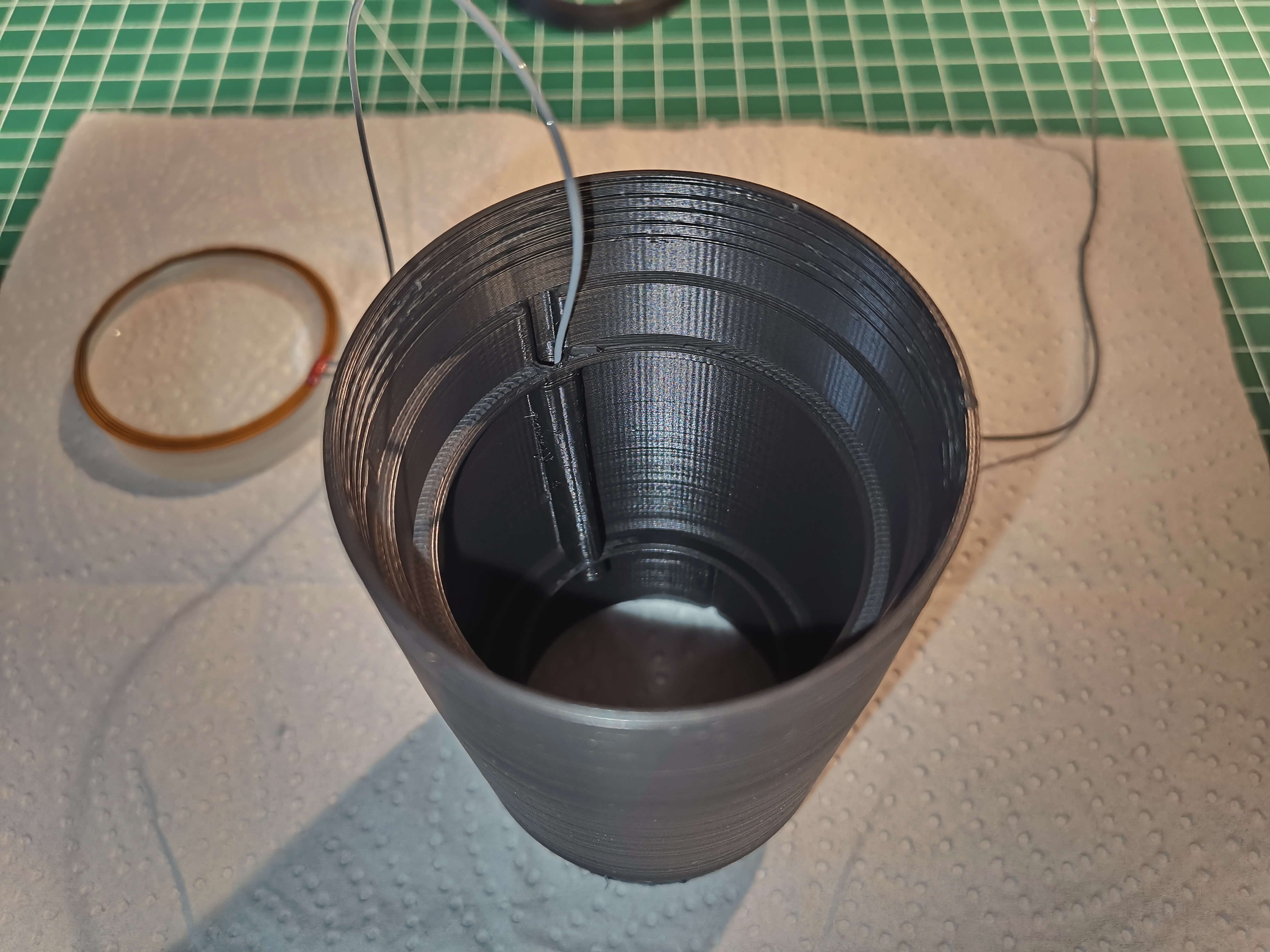
Now take the front part and route one of the cables of the dew heater through the small hole at the top. Only one cable fits through at a time.
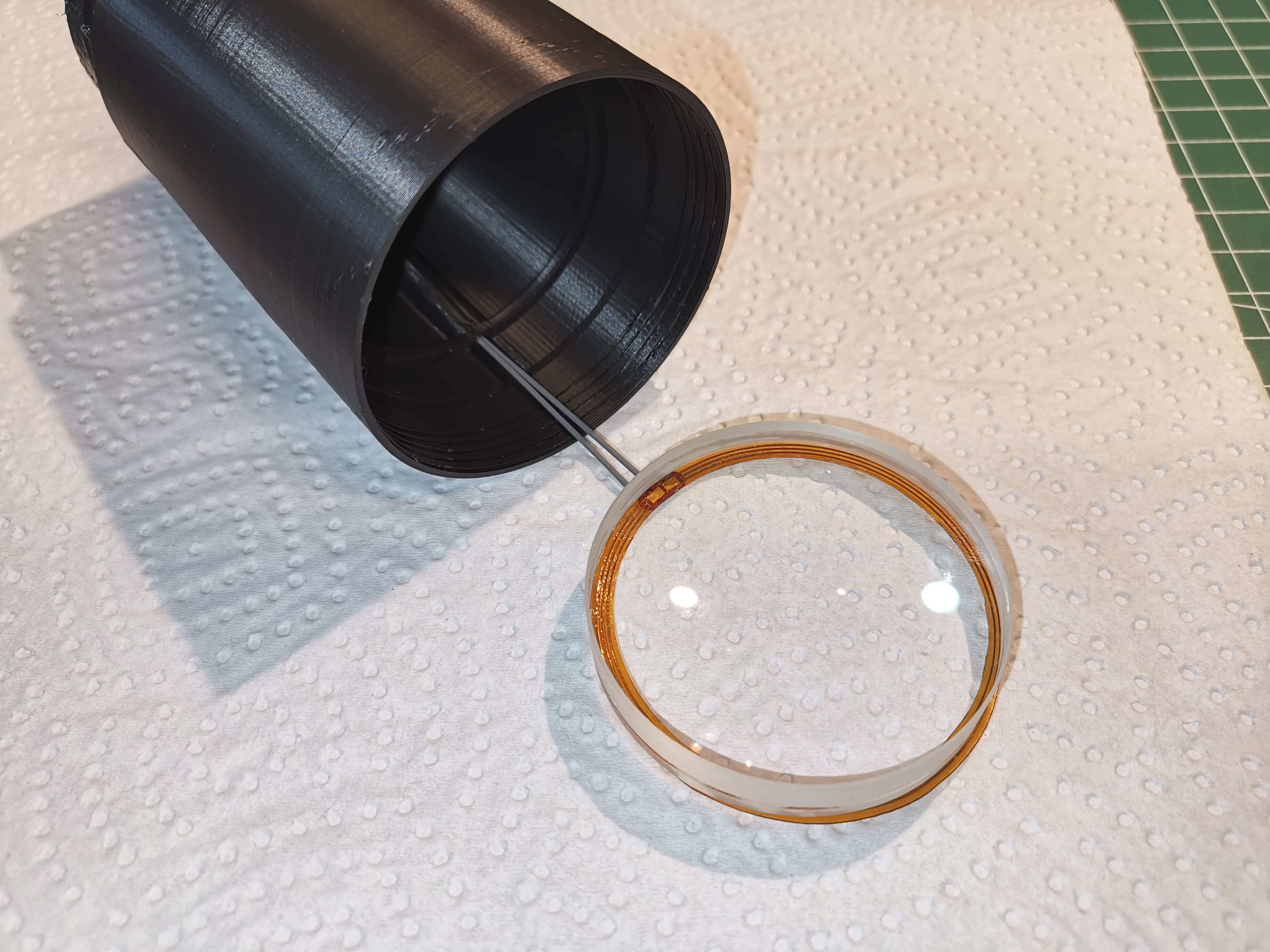
Route the other cable through too and pull the lens in slowly. Make sure the cables arent twisted.
Note the lens is laying on it's front side (dew heater side) in the image.
Now carefully place the lens in the front piece. Use a piece of paper or gloves to not get fingerprints on the lens.
Make sure the red part of the dew heater is right over the cable channel.
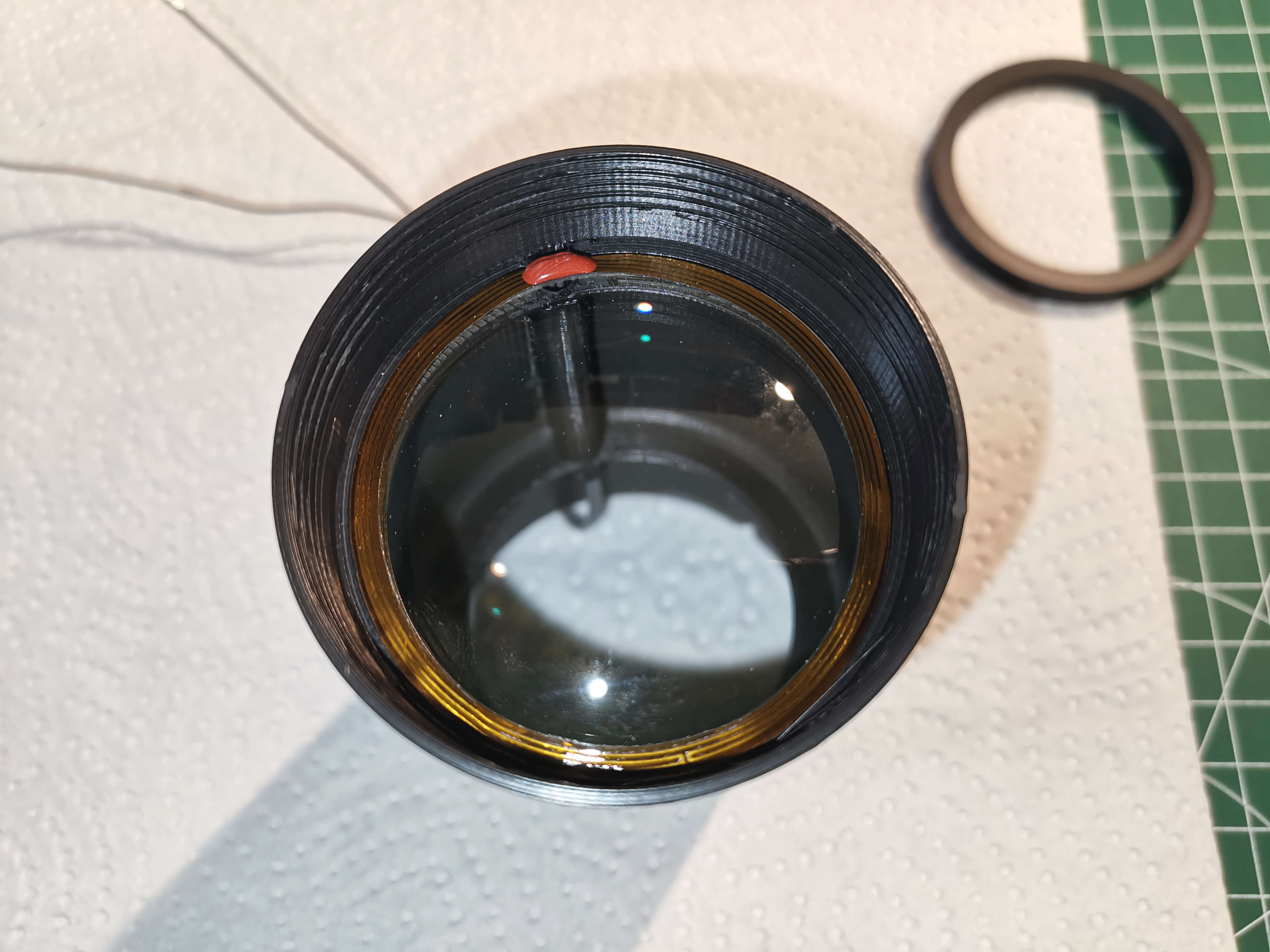
Place the lens_holder over the lens. The small cutout should fit over the red part of the dew heater.
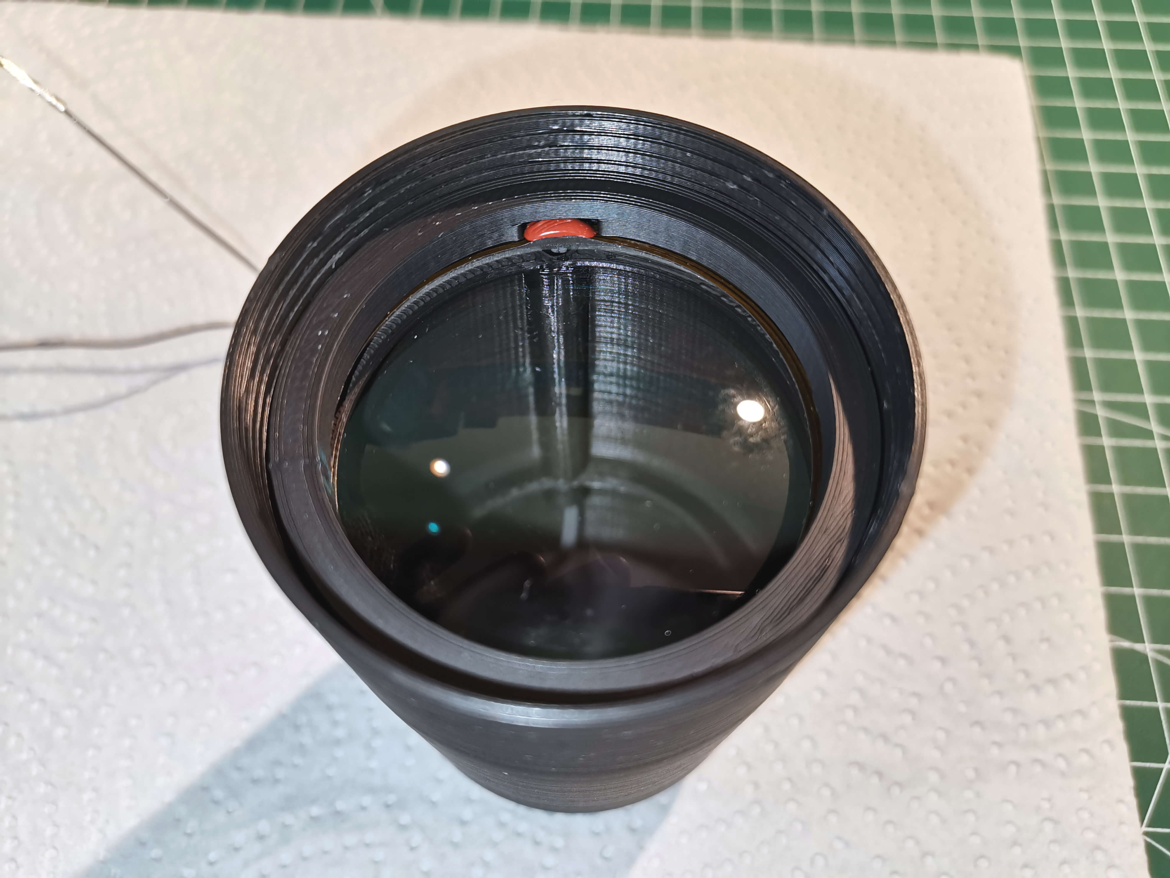
Screw on the dew shield. Only tighten it very lightly and make sure the lens_holder doesn't turn while doing so!
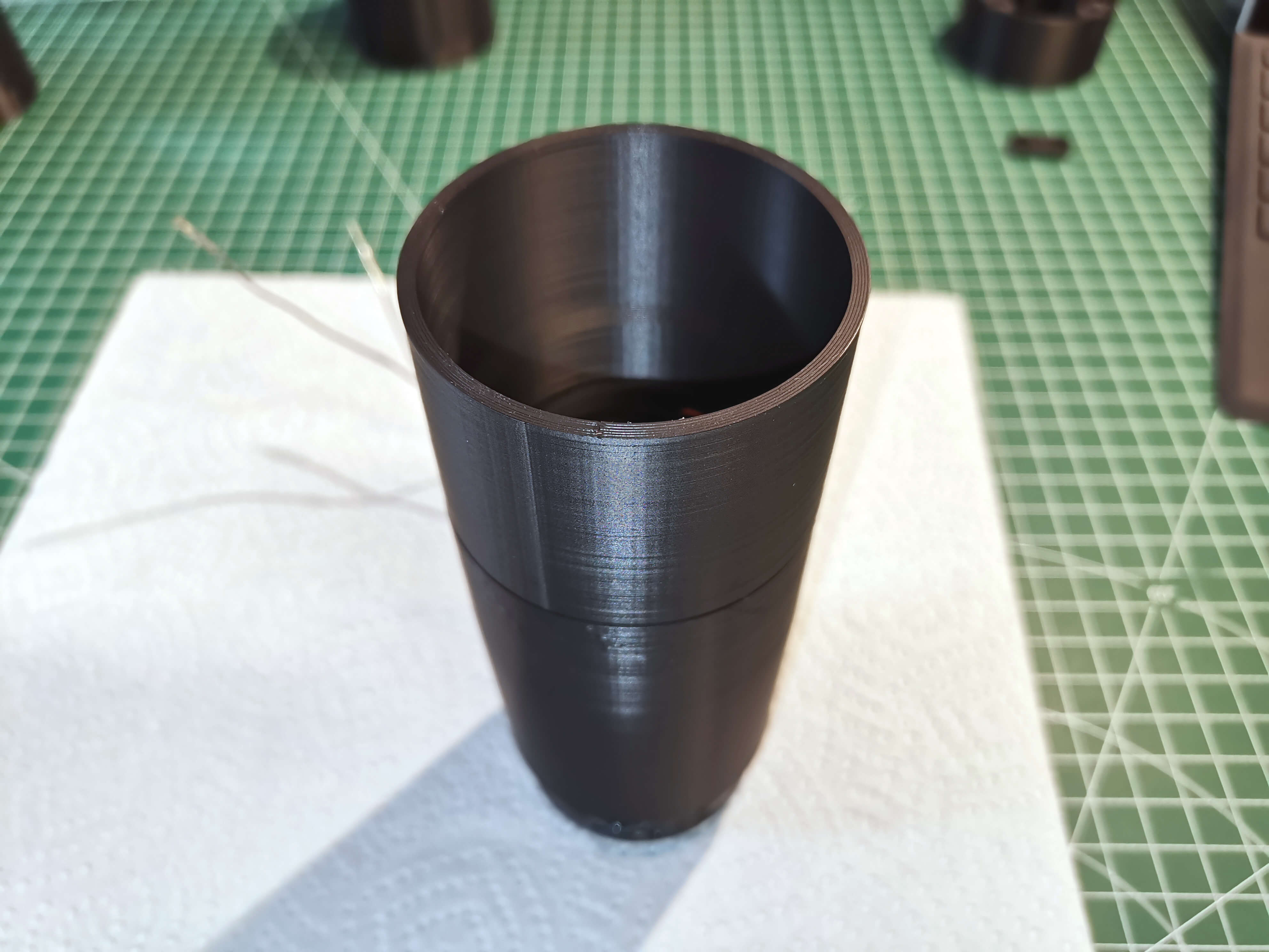
Route the cables through the mid section and screw it on by one or two turns. There is a small arrow on it that indicates the correct orientation, make sure it faces towards the front.
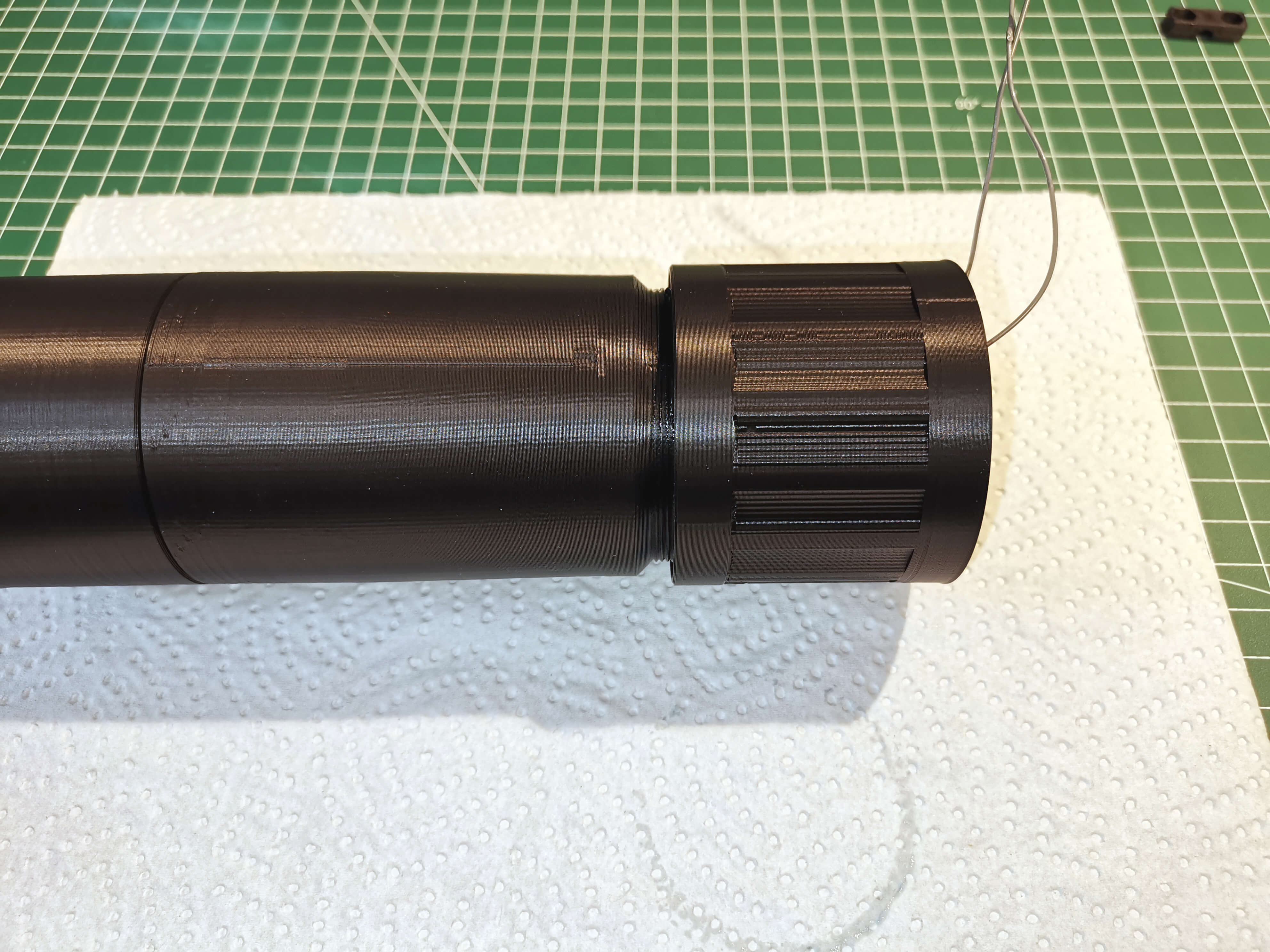
Take the rear section. There is also a small cable channel. Route the longer cable through and get the shorter one in as far as possible.
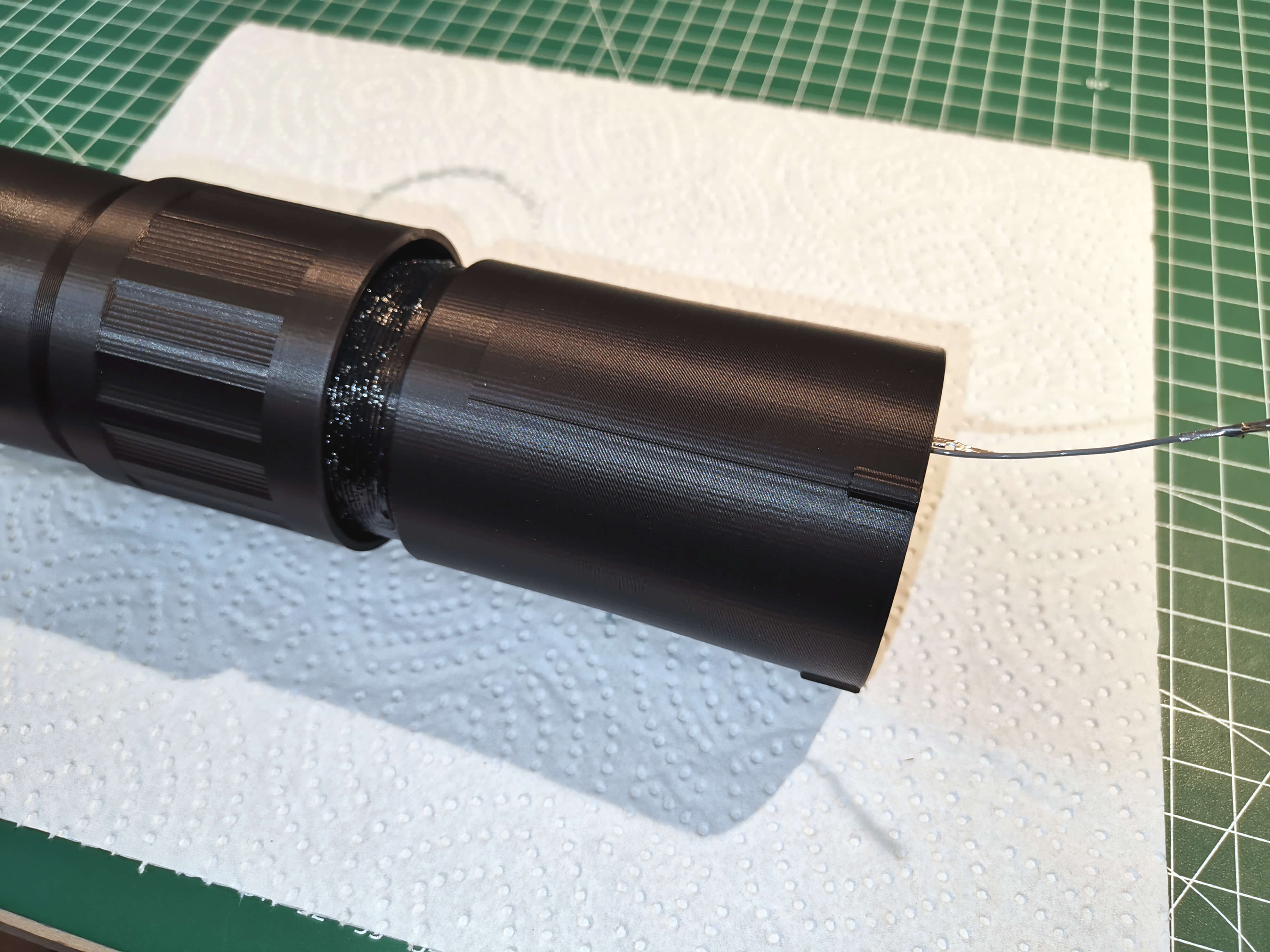
Now comes a very fiddly step. There are two "T" shapes printed on both front and rear. Align them.
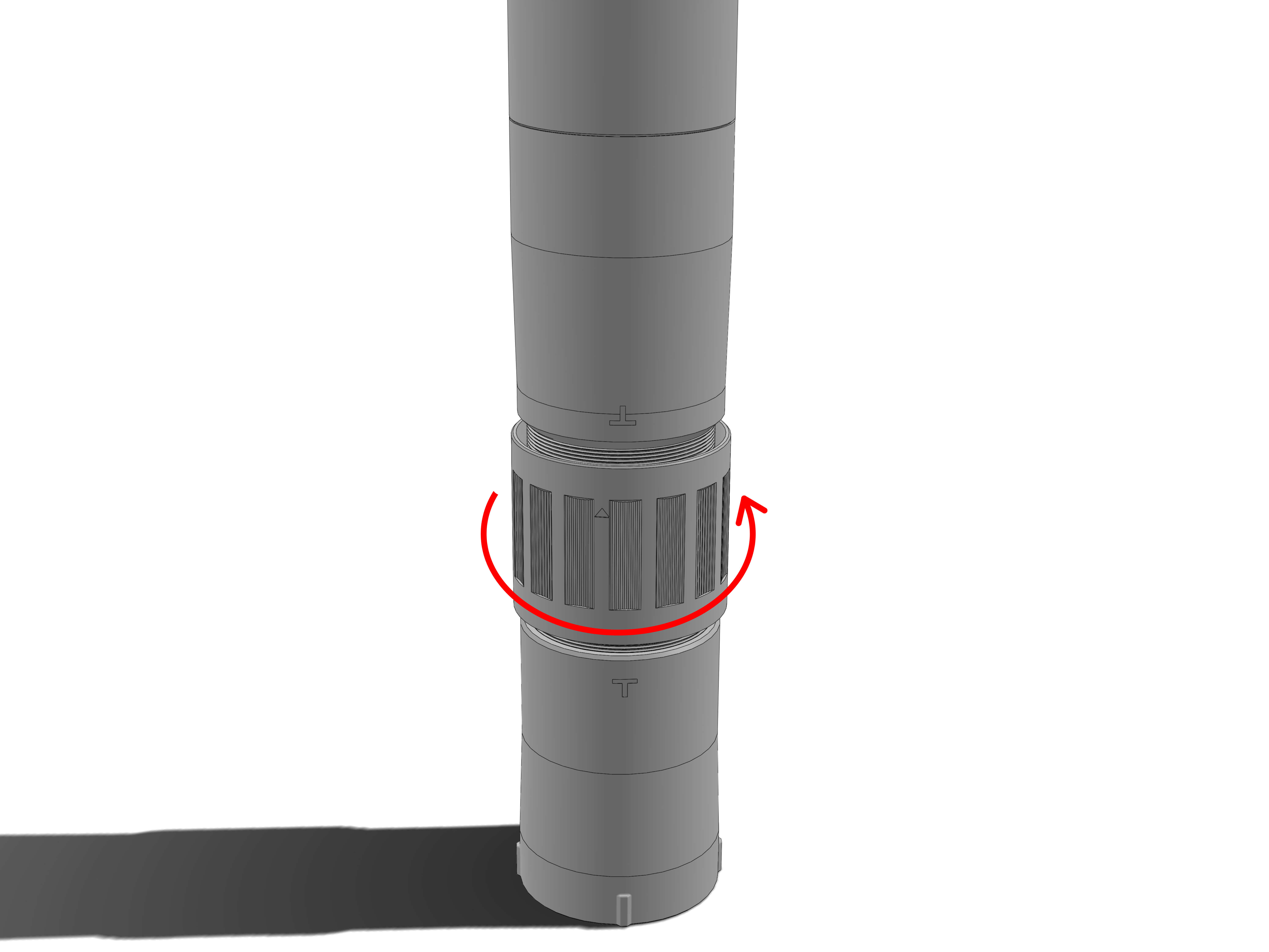
Hold the front and rear in one hand and make sure the rear is touching the mid's thread as straight as possible. Then rotate the mid righthand to catch the rear thread. This might take some tried. Once it has caught you can continue turning until the sprockets inside catch. You might feel a little resistance, but don't use force. As long as the "T" shapes are aligned it should go in very easy.
Once the sprockets have caught you can rotate the focuser without holding front and back.
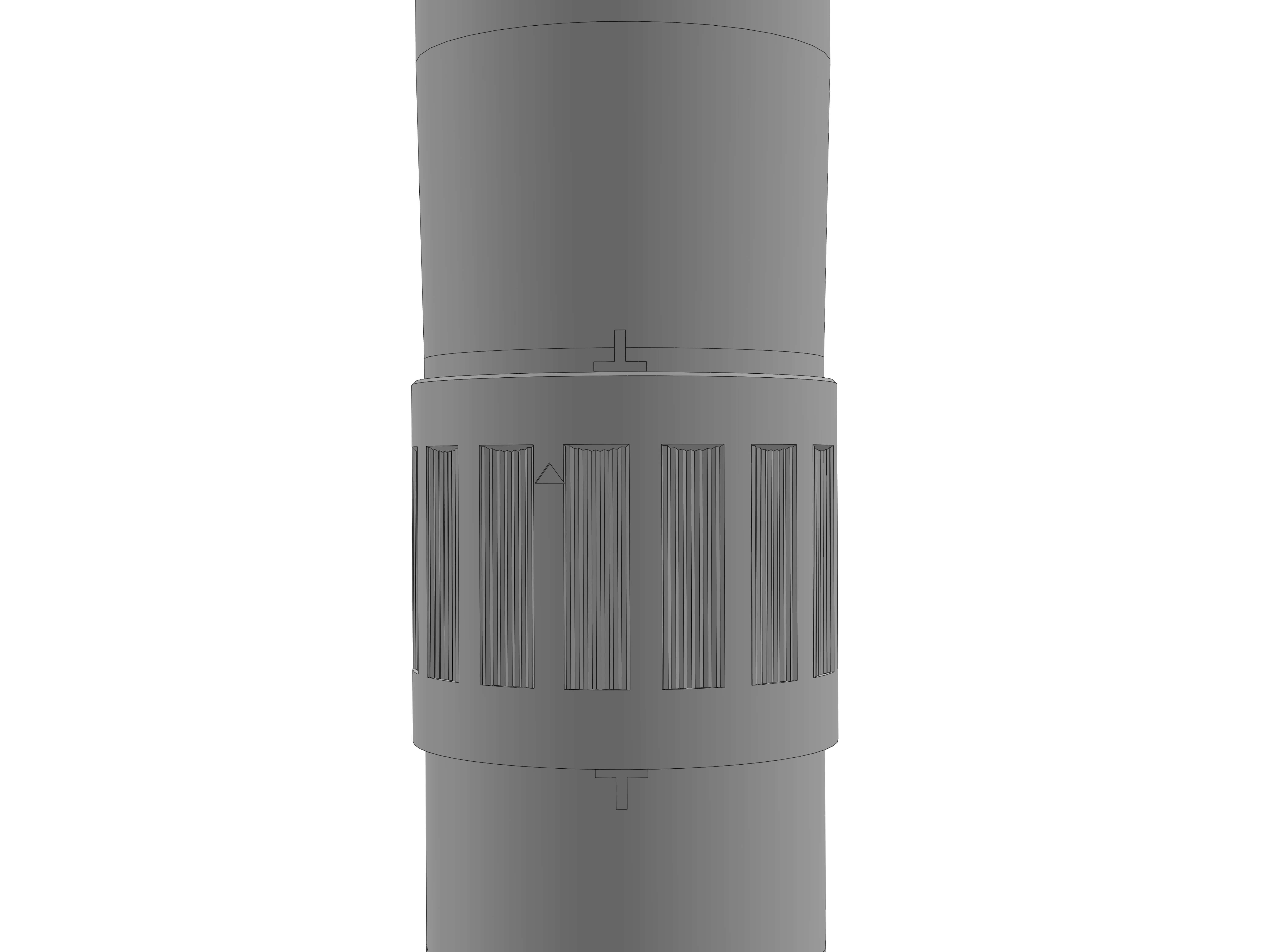
Continue rotating the mid until it's edges have roughtly reached both "T" shapes.
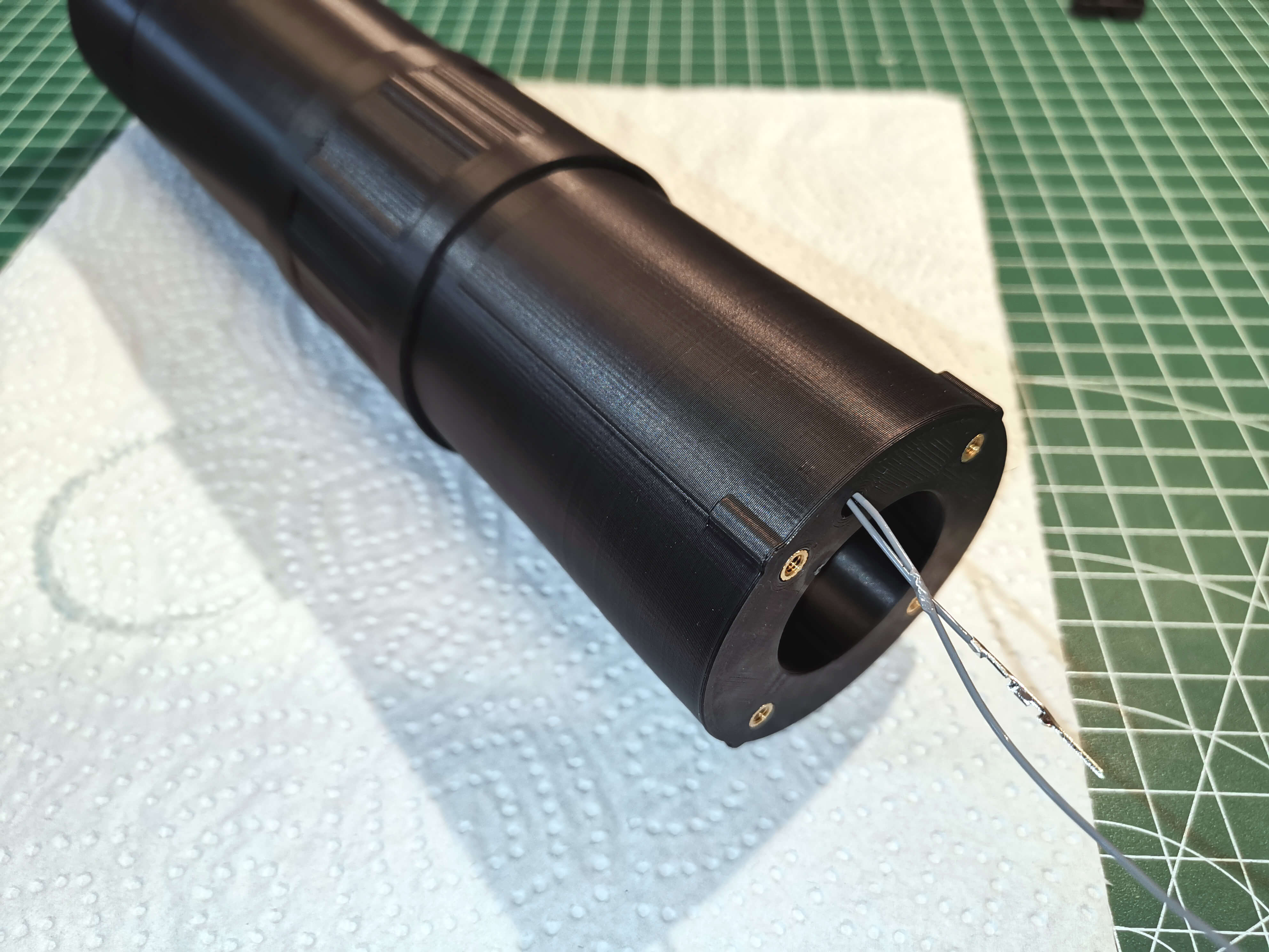
With front and back screwed in, both dew heater cables should now stick out the back.
Place the two black pin holders over the ends of the wires. There are openings on top of the metal wire ends that align with a spring loaded tab on the black sheaves so that they snap into place.
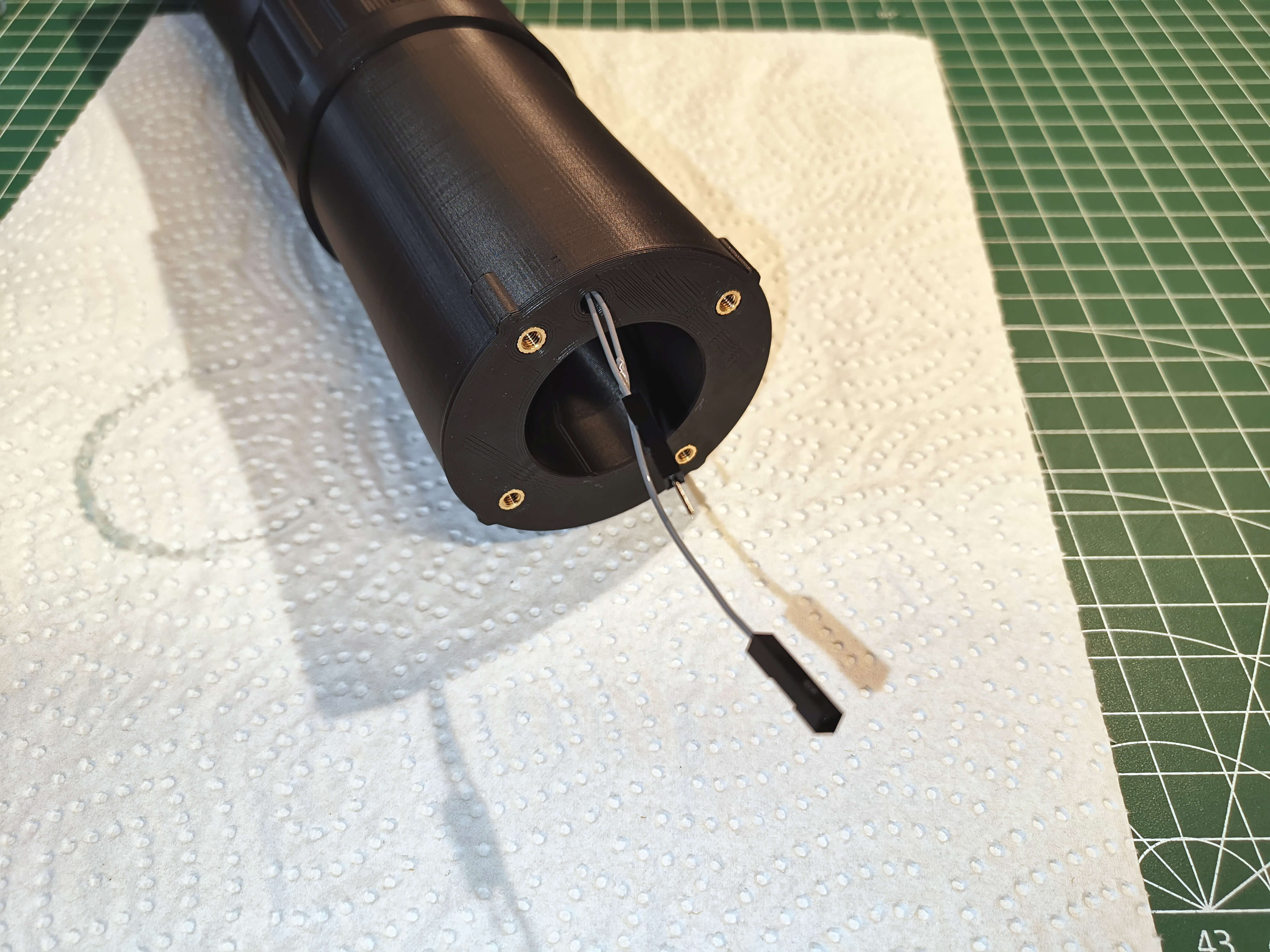
Connect the wires to the plug as shown. If you have extra heat shrink tubes, place a short piece to keep the insulation in place.
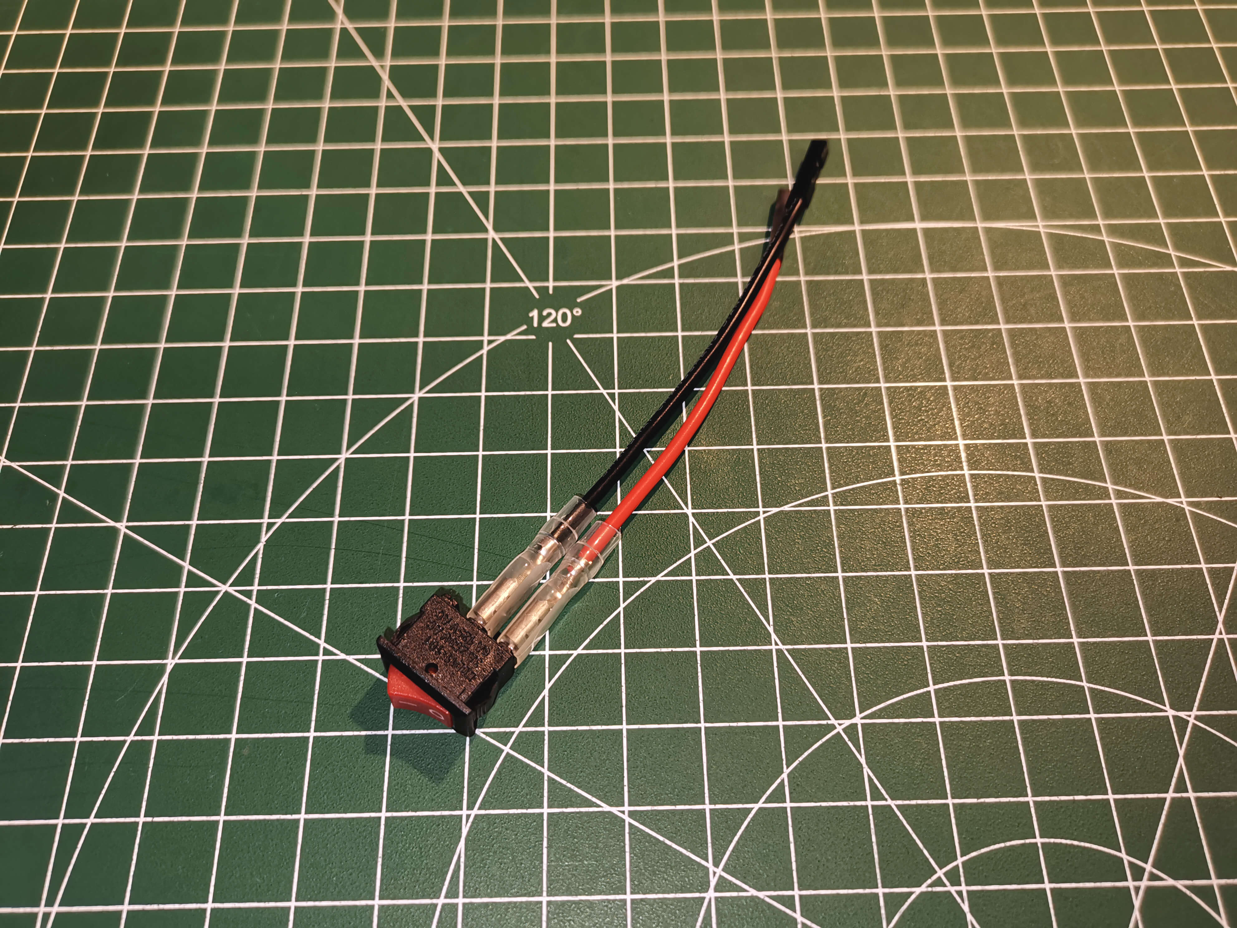
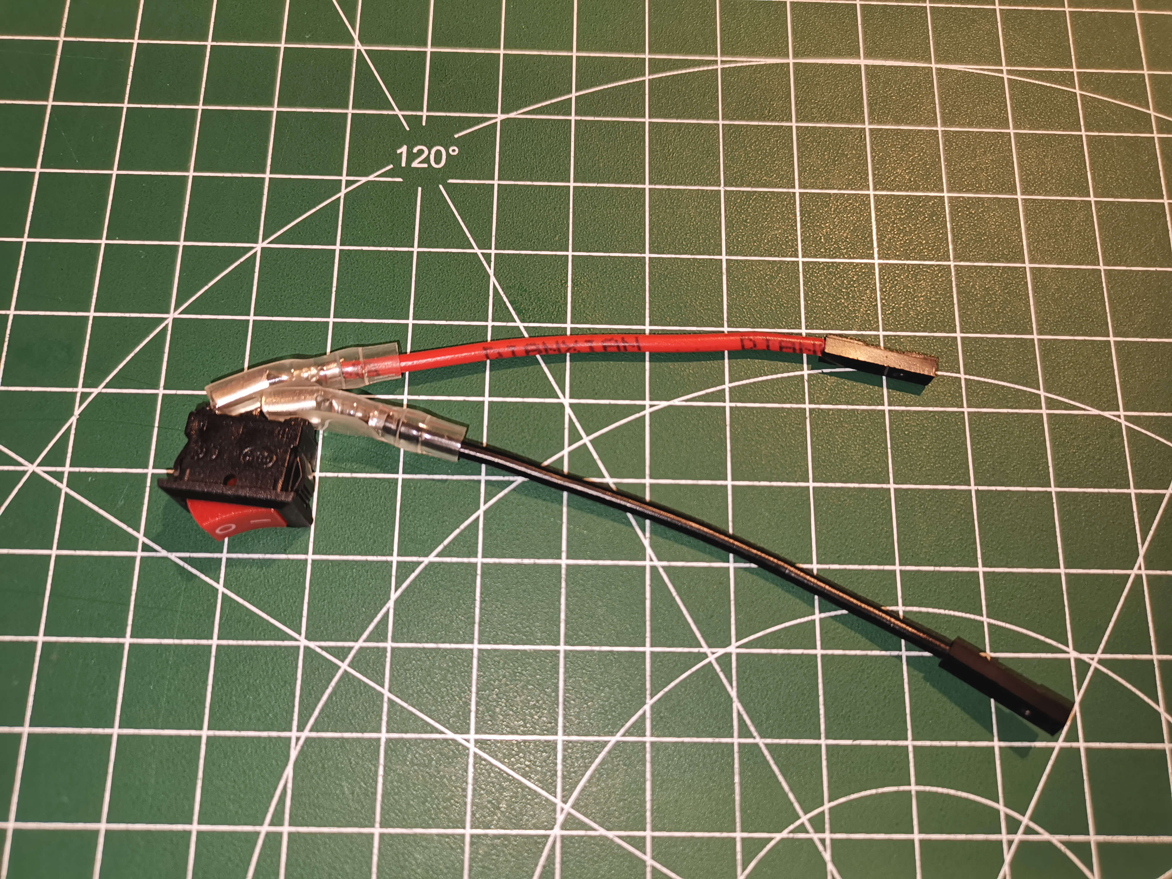
Bend the wires as shown.
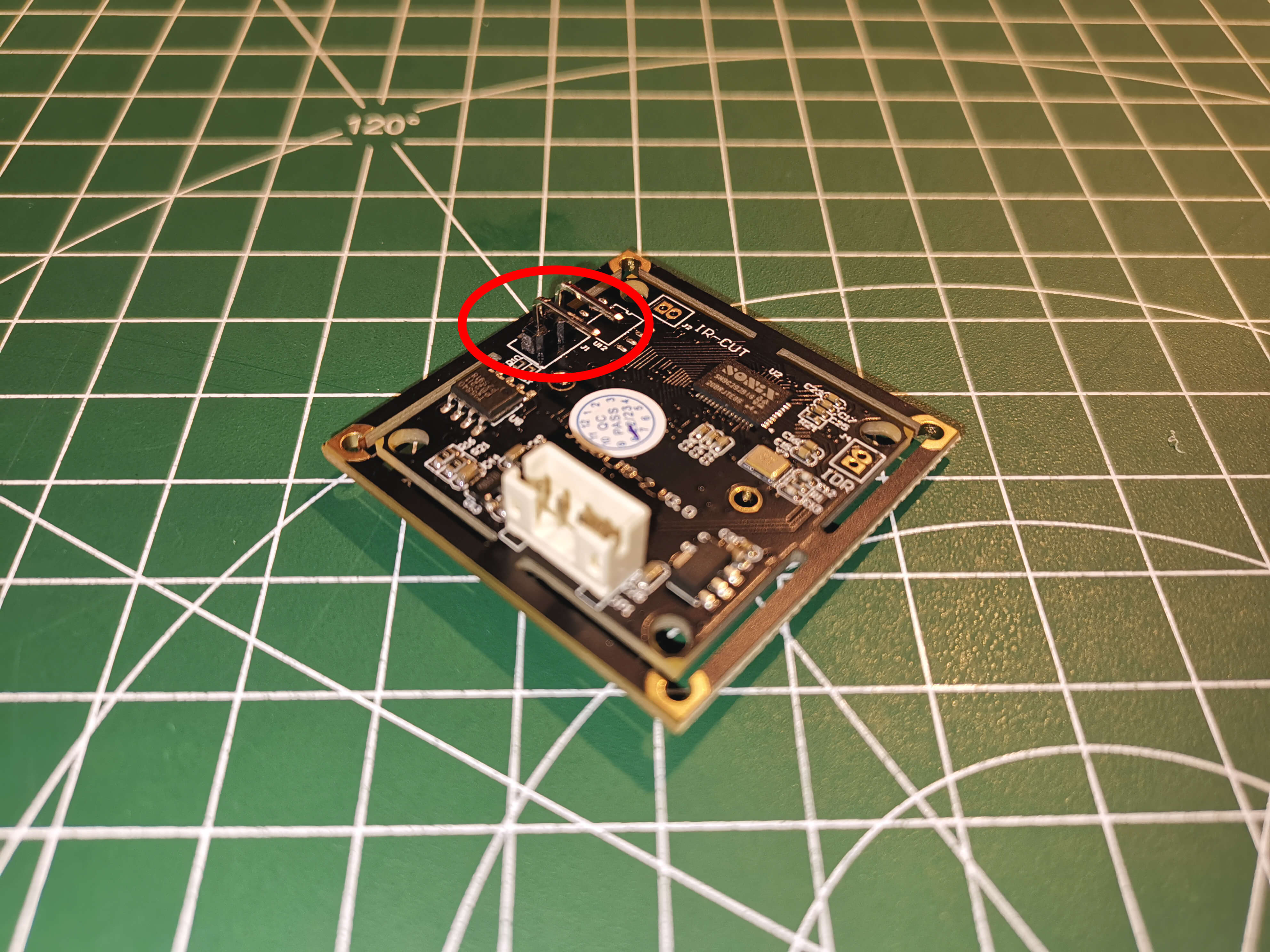
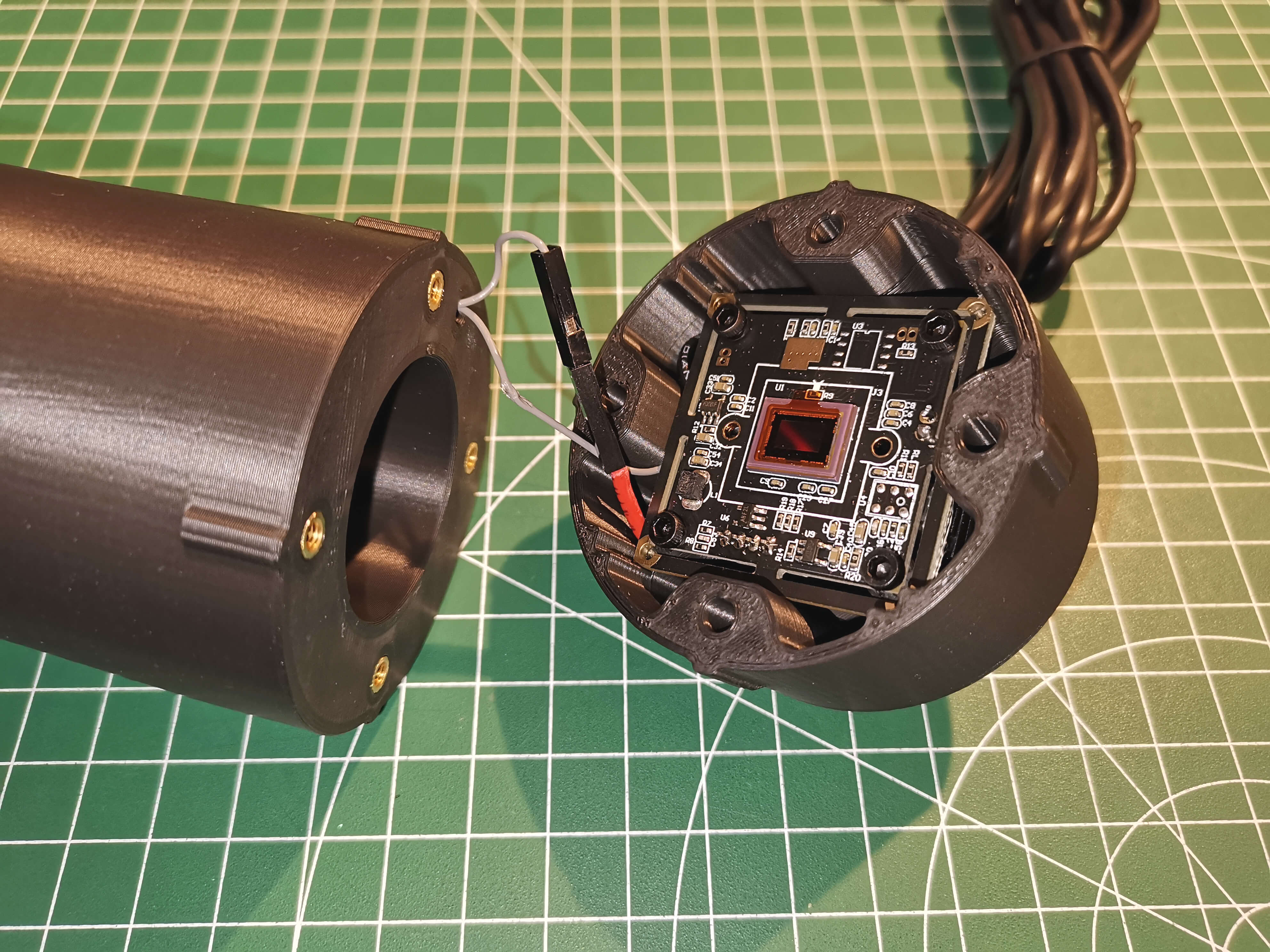
Check to see whether your camera module has the 5V/Gnd holes for the 2-pin header that came with the guider kit.
If you have a different camera module, like the one below, you may have to tap into the 5V and GND from the header.
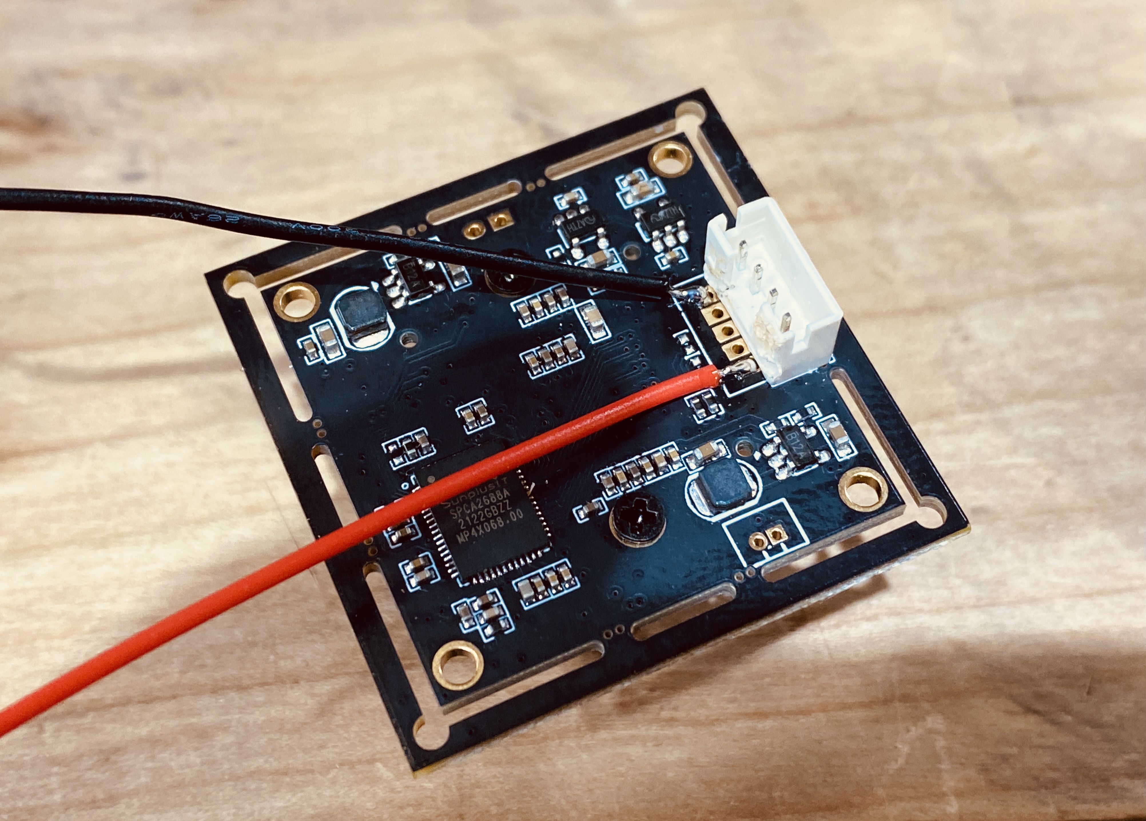
Otherwise solder the 2-pin header to the board as shown.
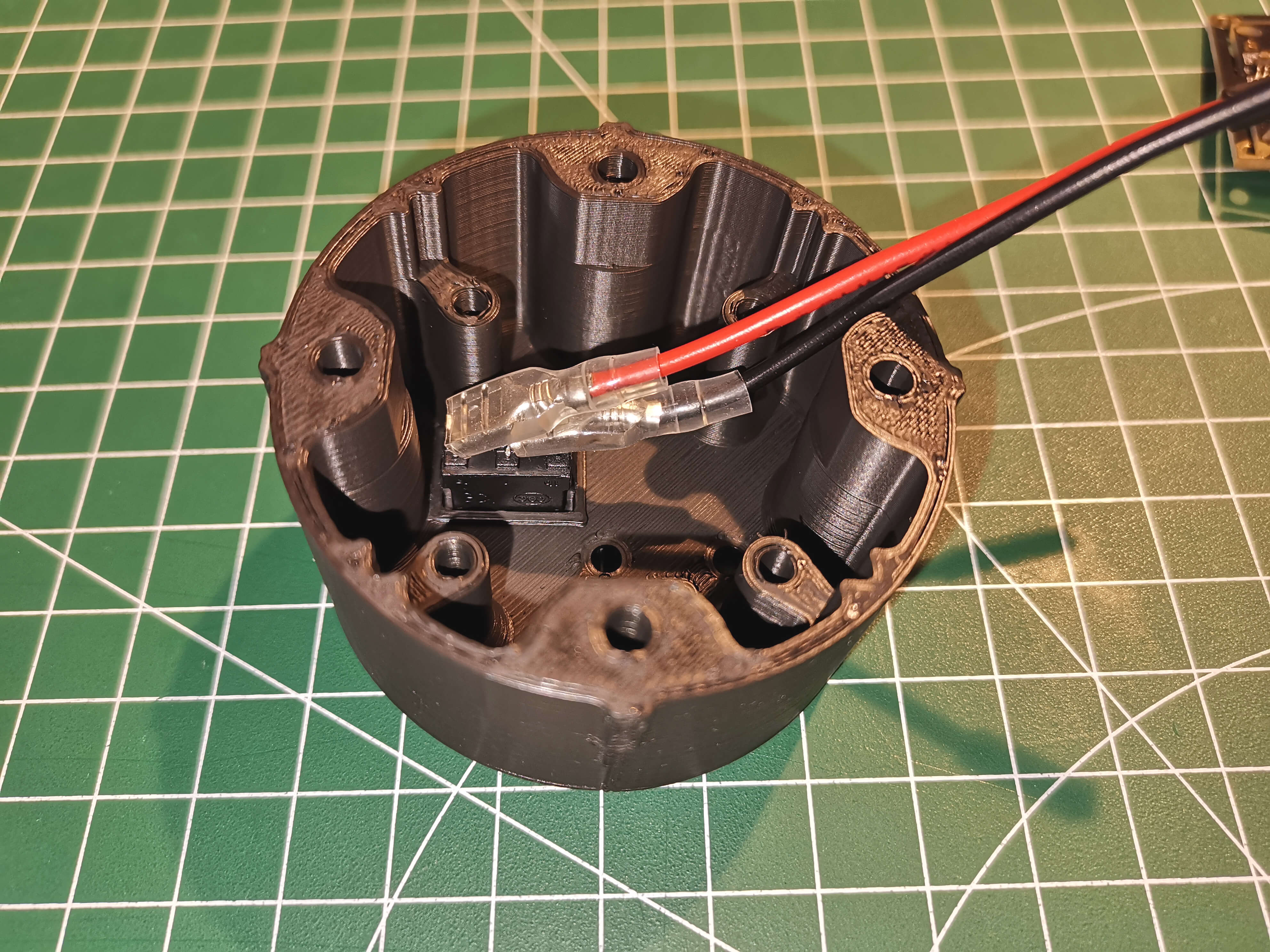
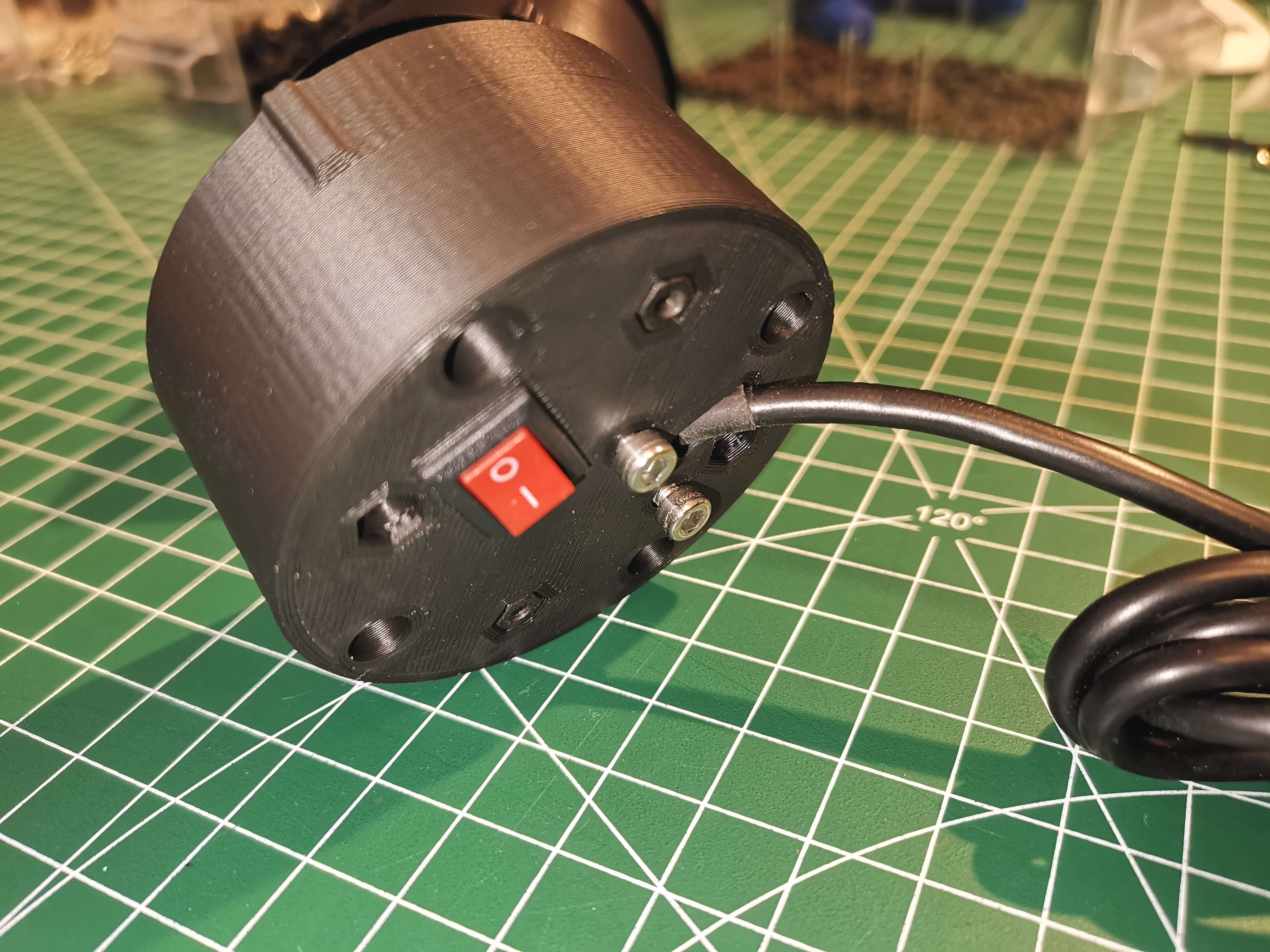
Install the switch in the end of the guider body as shown.
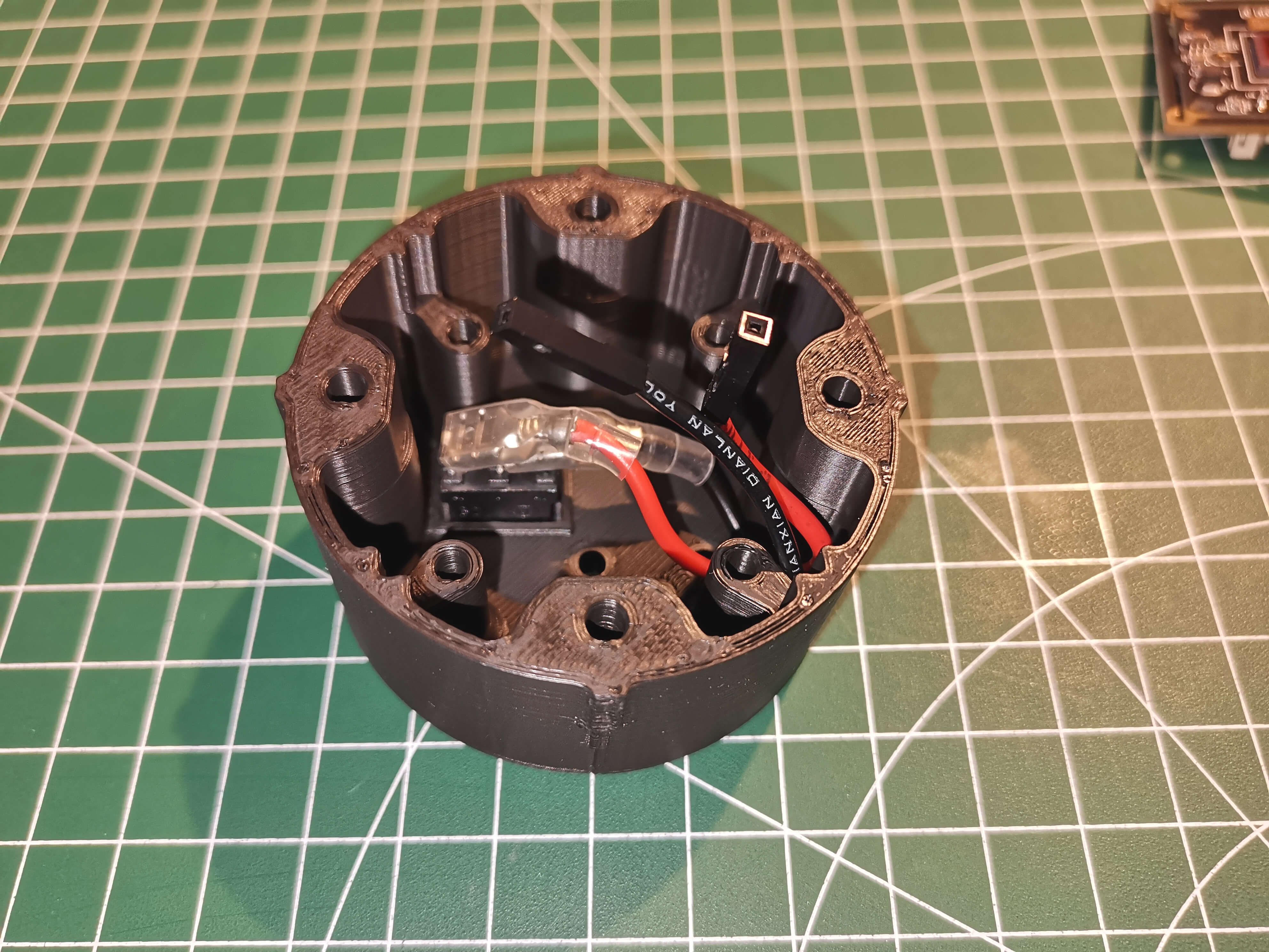
Push the wires into the body of the guider camera housing
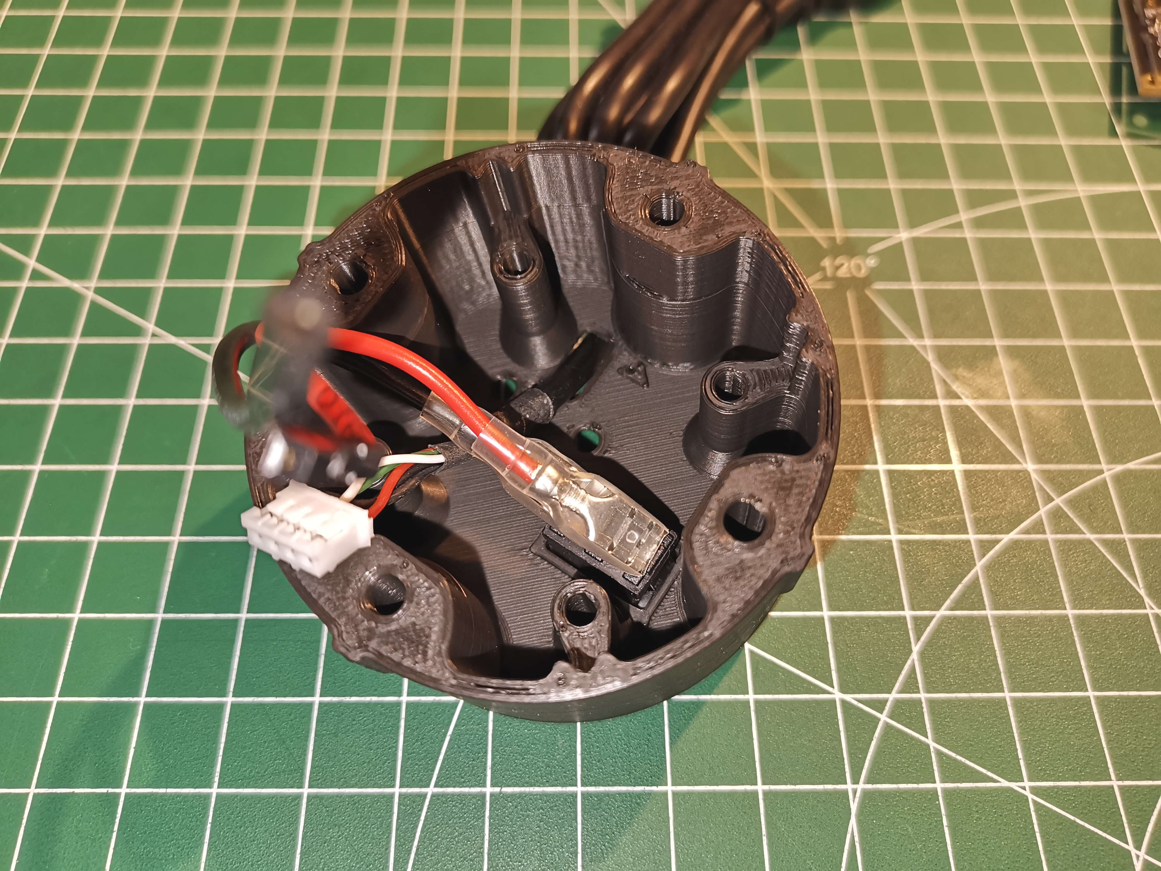
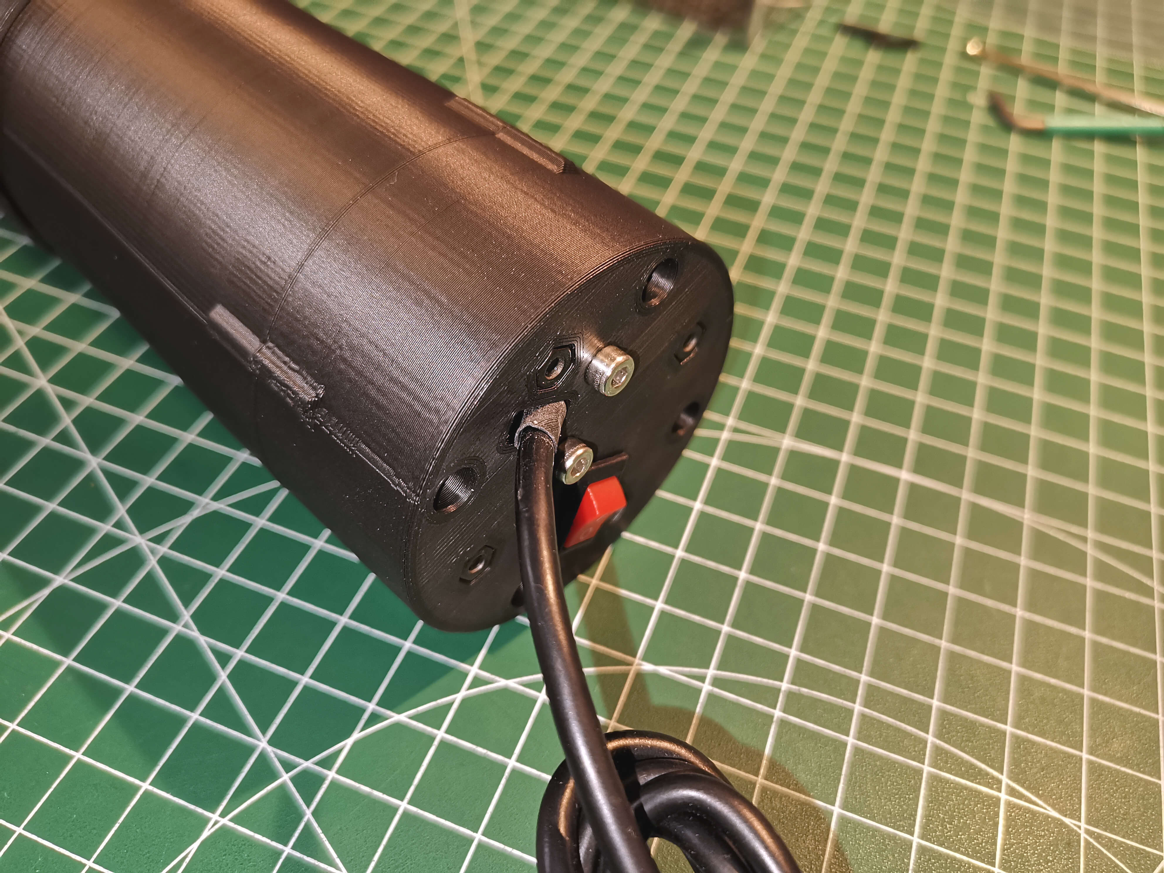
Pull the USB cable and install the cable tension release with two screws and nuts.
Connect the black cable from the switch with the GND pin or wire.
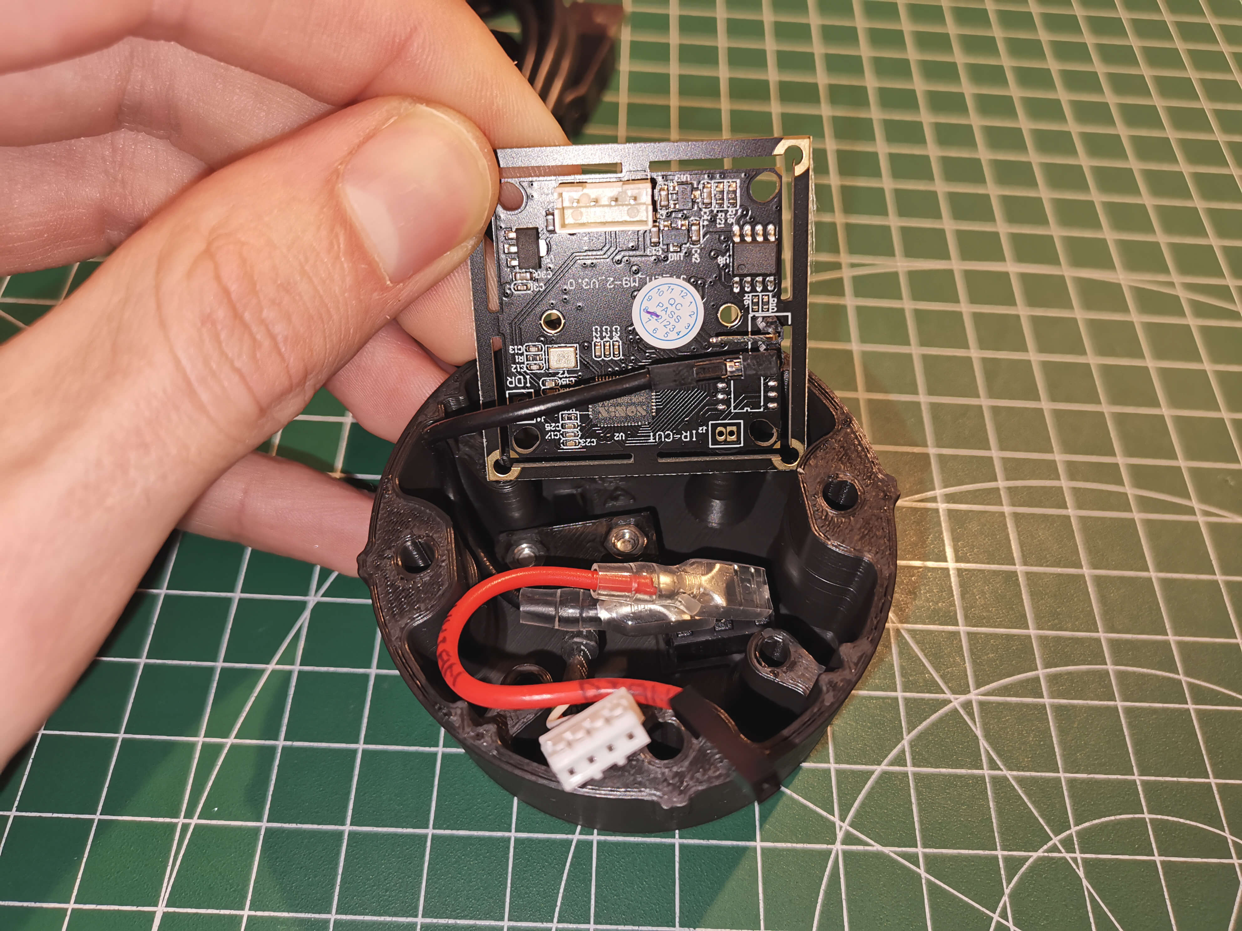
Connect the grey wire with the female end from the dew heater to the 5V pin or wire.
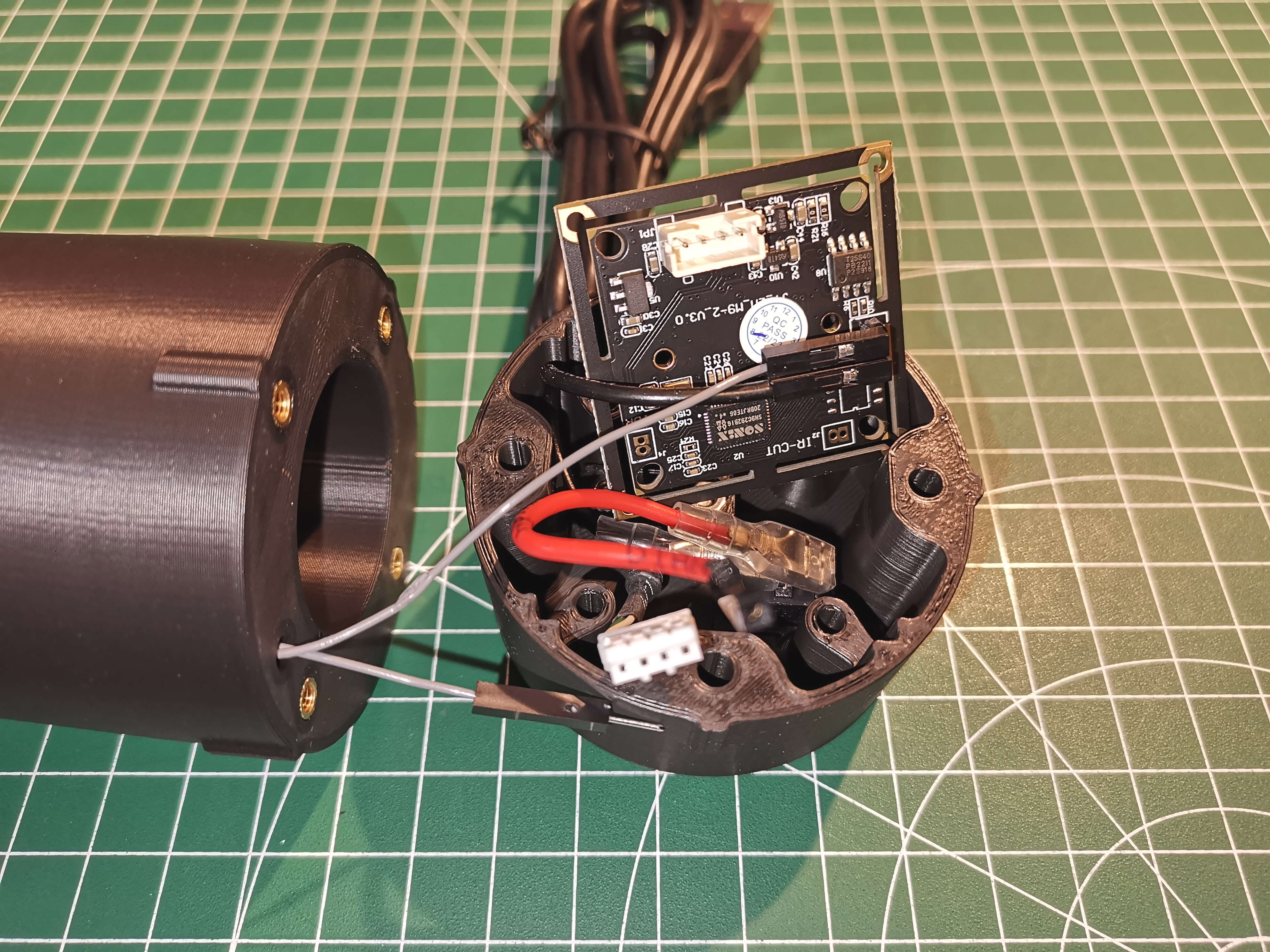
Connect the grey wire with the male end from the dew heater to red wire from the switch.
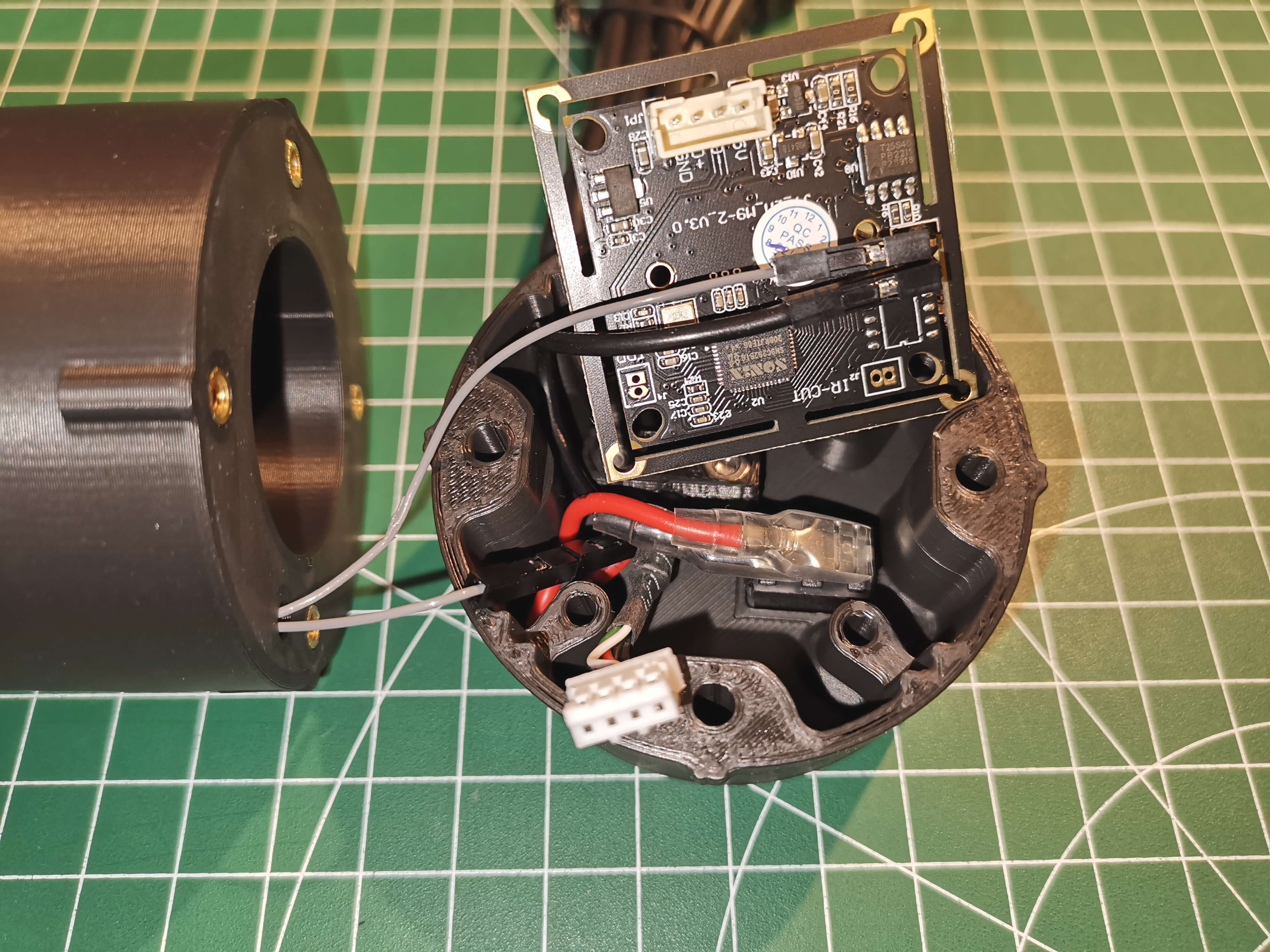
Connect the USB connector to the camera board.
It is recommended to connect the camera at this point and make sure everything is working and the switch has no influence on the camera.
Push all the cables under the camera board and screw into place.
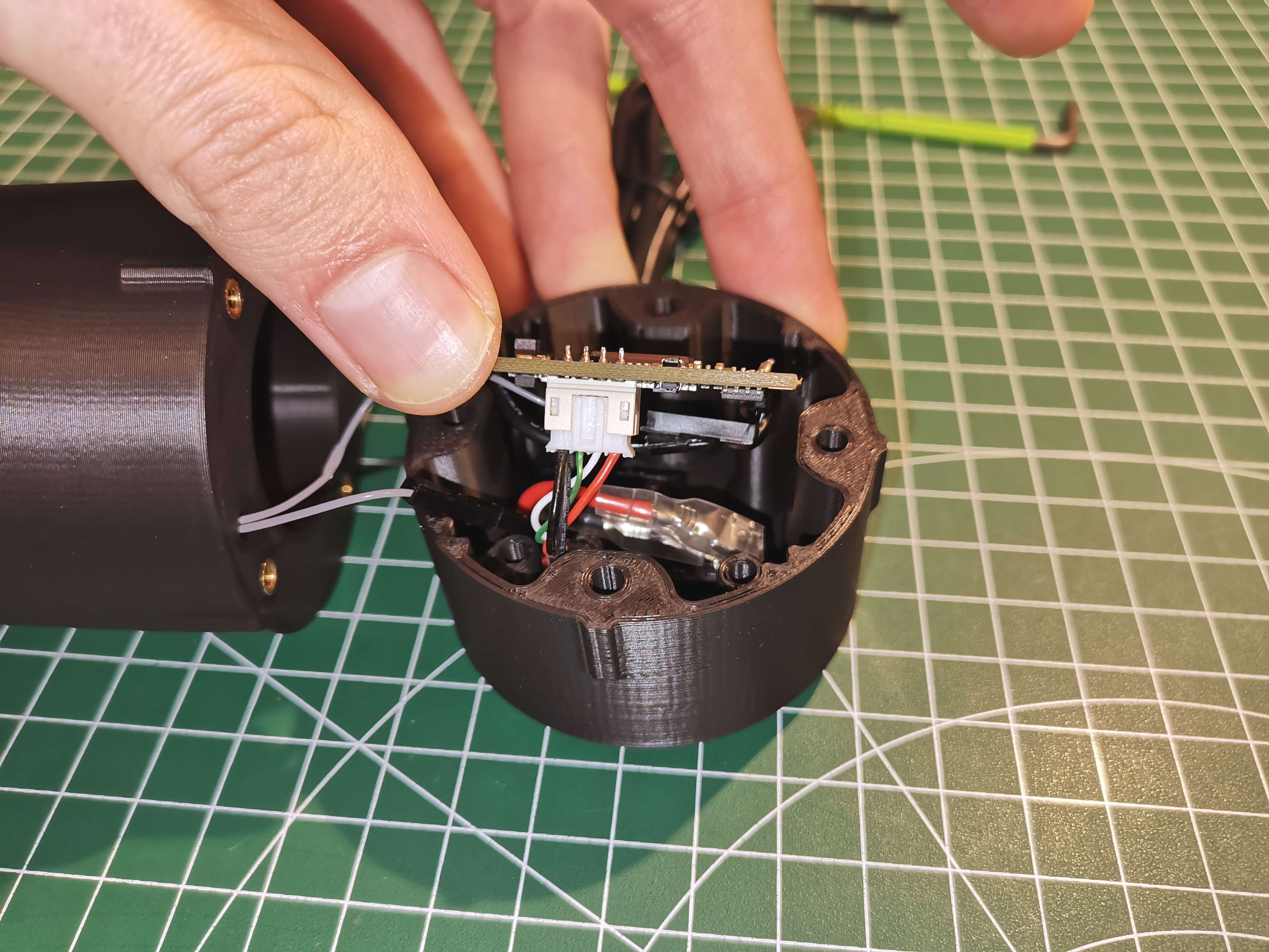
Tighten the two screws of the strain relief. This doesn't have to be overly tight, only so much that the cable cant be moved.
If you haven't already, now is a good time to remove the little protective film from the sensor.
Attach the camera to the rest of the guider with 4 M3x20mm screws. The orientation doesn't matter, but the 4 notches have to align. Before tightening the screws, shine a light into the guider and make sure no cable hangs infront of the sensor.
For information on how to attach the guider, see either the Vixen Mount or OpenAstroTracker section of the main instructions.